nILS
-
Posts
4,314 -
Joined
-
Last visited
-
Days Won
4
Content Type
Profiles
Forums
Blogs
Gallery
Everything posted by nILS
-
Do NOT use mono cables in a stereo socket, because that essentially grounds the one of the SID outputs. Can you show some pics of the base PCB please (top and bottom view), maybe we can catch sth there... Also, since this thread is getting kinda long, would you mind posting a short summary of the current status? Just a quick overview overview with: - wallwart specs (+ measured wallwart output) - voltages on the 5V and 9V rail - all jumper positions (use the 6582 settings and 6582 ICs for now) - short description of the exact problem Maybe that helps us to refocus and not get lost on details like the audio sockets.
-
Being a big fan of symmetry it seems kinda odd to me that the OSC and CONTROL sections do not align with the FILTER and LFO sections. Also, the engraving seems horribly close to the LEDs on OSC and CONTROL. That seems to mostly be the case because of the logo, which also leads to the screws being all over the place. Not even the knobs are aligned vertically... Are you a southpaw? I would also consider switching the fan thingie and the phones jacks. Everything that has cables coming out of it should be as far away from anything else as possible imo. The way you have laid out the two rows of buttons per section seems kind odd as well... For the LFO section, the LFO selection is the 2nd row, while on the OSC section, the OSC selection is the 1st row.
-
Ich hau mich weg! I just laughed so hard, I woke the missus up :thumbsup:
-
Actually janis beat us both to it, while I was looking for a pic ;)
-
Let's see if you can figure it out yourself. No help please. (Sorry janis, I removed your post to allow Snoozr to solve it himself)
-
[SOLVED] Midibox Sid can't upload setup6581.HEX
nILS replied to Waxx's topic in Testing/Troubleshooting
By editing the first post using the "use full editor" button. I went ahead and did that for you. -
Taster und Encoeder haben nicht wirklich einen Widerstand. Der ist im Prinzip unendlich oder 0. Könnte? Kannst. Die AINs vertragen sich mit 10k (linear) am besten. Was meinst Du denn mit Matrix? Alle Pin 1 (CW) kriegen 5V, alle Pin 3 (CCW) kriegen Masse und alle Wiper gehen einzeln an die AINs.
-
Damit's aus dem Weg is. =pot&s[]=encoder#what_s_the_difference_between_potentiometers_sliders_motor_faders_and_encoders]Siehe WIKI Nö.
-
Not me. crystalfontz has those as well, and they're on my ToDo list... :)
-
/* * * * * * * * * * * * * * * * * * * * * * * * * * * * * * * * * * * * * * * * * * ,dPYb, 8I * * IP'`Yb 8I * * gg I8 8I gg 8I * * "" I8 8' 8) "" 8I * * ,ggg,,ggg, gg I8 dP ,g, dP ,g, gg ,gggg,8I * * ,8" "8P" "8, 88 I8dP ,8'8, ,8'8, 88 dP" "Y8I * * I8 8I 8I 88 I8P ,8' Yb ,8' Yb 88 i8' ,8I * * ,dP 8I Yb,_,88,_,d8b,_ ,8'_ 8) ,8'_ 8) _,88,_,d8, ,d8b, * * 8P' 8I `Y88P""Y88P'"Y88P' "YY8P8P P' "YY8P8P8P""Y8P"Y8888P"`Y8 * * * * n I L S ' S I D E M U L A T I O N * * * * * * * * * * * * * * * * * * * * * * * * * * * * * * * * * * * * * * * * * */[/code] After kinda forgetting about it, I stumbled across the SID-Player I wrote to test the SID-emulation on the core32 a while back. It's called [b]nEMU[/b] and all it needs is a core32 module. :frantics: Simply upload the app to the core32, point ASID XP or [i]$your_fav_sid_player[/i] its way and off you go. The stm32's internal DAC provides the audio out of the 2 emulated SID chips on J16:SC and J16:RC1. The application responds to a few CCs: [code]CC#7 Master volume CC#8 Delay tap, left channel CC#9 Delay tap, right channel CC#12 Resonance bandwidth for RES_SVF CC#13 Cutoff control for RES_SVF CC#14 Select filter type (0, 1, 2) CC#15 Filter dis/enable (0 or 1) CC#127 Resets the application This is in no way a good or authentic emulation. This is just a toy :thumbsup: Here's some sample songs with me fiddling with the filter settings: http://www.schickt.de/mb.org/nsid.mp3 nEMU-internal-dac.hex
-
a) Um das LCD wirst du vermutlich mehr Platz brauchen b) Kontrastpoti würde ich vermutlich nicht auf dem Panel haben. Den verstellst man eher selten - selbst als Lichtmensch. Selbst schon probiert ;) Außerdem bringt der Kontrast unabhängig vom Backlight nicht so viel. Also lieber beides hinten ran. c) die Buchse für den Schwanenhals würd ich ganz nach außen setzen. d) was sollen denn die Xtra Potis regeln? Evtl. doch lieber Encoder? e) Ich finde LCD Menüs deutlich besser bedienbar, wenn die Taster unter den entsprechenden Items sitzen und es einen Encoder zum verstellen der Werte gibt. f) Ich fand es bei allen bisher verwendeten Lichtpulten immer super, wenn zu jedem Kanal angezeigt wurde, welchen Wert er im Moment hat - speziell, wenn Du keine Motorfader hast. Ein 7-Segment LED pro Kanal kann da Wunder wirken g) Die Page-Buttons sollten unbedingt LEDs drinne haben (falls das nicht so geplant war)
-
Das ist keine Lösung sondern ein Kurzschluß mit blauem Qualm.
-
Parallel würd ich garnicht machen, das ist unsauber und unnötig. Bild anhängen: 1) "Use Full Editor" 2) Datei auswählen 3) "Attach this file" 4) "Add to post"
-
http://ucapps.de/mios/midibox_sid_v2_0_rc37.zip > presets
-
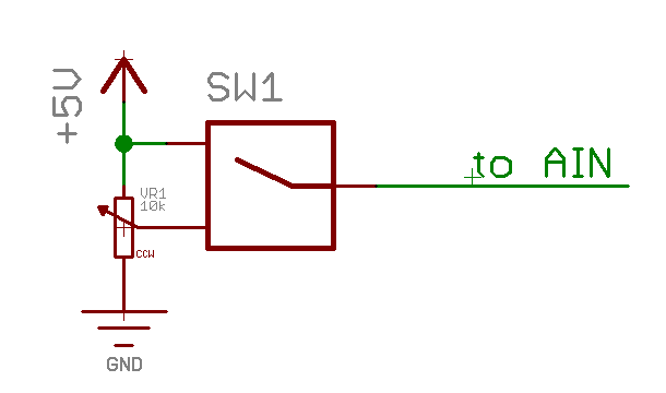
SPDT. Ist nicht nur die eleganteste sondern auch die einfachste Lösung :ahappy:. Mit 10k am wiper kommst Du am Ausgang nicht mehr über 4.98V. Geht Dir also am oberen Rand ein Teil der Auflösung flöten.
-
http://tinyurl.com/4jlvnff
-
Das hätte schon gereicht. Du willst einen SPDT Taster. Fertig. Ein Eingang auf 5V, den anderen auf den Ausgang vom Fader. Den Ausgang des Schhalters aufs AIN. Bez. der restlichen Fragen: Mal was was. Das hilft ungemein. Mehr DIN kriegst Du z.B. über eine Matrix. Oder mit mehr Cores. Die können über CAN oder MIDI kommunizieren. Displays brauchst Du gar keine, ist aber oft hilfreich. Wie gesagt, Butter bei die Fische, mal uns mal ein kleines Konzept wie das Dingen aussehen soll, das hilft meistens :)
-
The individual pitch bend ranges are not implemented yet... :whistle: Nice work, TK!
-
The LFOs are generated in the PIC. So you just need to dig a little deeper in the source ;) \src\sid_se_l.inc might be helpful as a start
-
Kann er nicht. Weil dann der analoge Eingang floatet und du nicht den Hauch einer Ahnung hast, was da am PIC ankommt. Ehrlich gesagt, jab ich nicht auch nur in Ansätzen verstanden, was genau Du gerade vor hast. Versuch es doch mal mit einer kurzen und präzisen Beschreibung dessen, was Du erreichen willst.
-
Sorry to hear that... :hmm:
-
I'd say you want a core module, a relay, a battery and a bunch of super bright red LEDs.
-
Since this isn't really going anywhere, I'd suggest desoldering the vregs and testing them separately.
-
Boooring.
-
Both are stereo and identical.