Wilba
-
Posts
3,310 -
Joined
-
Last visited
-
Days Won
2
Content Type
Profiles
Forums
Blogs
Gallery
Everything posted by Wilba
-
U16,U17,U18,U19 are connected to the rotary encoders. U20 is connected to the switch matrix. So, it's possible that pins 3,4,5,6,11,12,13,14 (which connect to the D0-D7 pads/ribbon cable/CS PCB) for U16-U19 might be connected, because of the position of the rotary encoders will be "shorting" some of those pins to ground. That's normal. This makes it very hard to test for shorts for those pins, but it doesn't really matter because you will discover problems later when encoders don't work correctly. For U16-U19, shorts between those pins should have no effect on the switch matrix. However, there should not be shorts between pins 3,4,5,6,11,12,13,14 of U20. Putting the 74HC165 in U20 is effectively turning on the switch matrix so that any short on the CS PCB is now being read by the PIC. In this case, it's possible that one of the SID 1,2,3,4 buttons are being triggered. So you'll need to check the tracks from U20 for shorts... also tracks/pads near the SID 1,2,3,4 buttons on the CS PCB. Normally shorts occur there by the LCD being mounted... but if this is not the problem, then it's most likely a soldering issue... some blob of solder shorting between pins of the switches etc. and it's definitely a short, not a broken track or a bad solder joint that is not connecting a pin to the track.... missing connections would not create an "always pressed switch" effect.
-
SammichSID Problems (No sound - wrong voltage reading)
Wilba replied to Geir_Helgi's topic in Design Concepts
As I've clearly written in the guide and elsewhere, if you want to use 6581 SIDs you need a regulated 12V DC power supply... there is not a 12V regulator on the PCB... it needs to be regulated externally. This keeps things simple for the majority of people who will use 6582 or 8580 SIDs, and still allow use of 6581 for those people who really want to. It sounds like you are using an unregulated 12V DC supply and therefore will get higher voltage when the current load is less than the rating on the supply. I don't know exactly what it would be, but for example, a 12V DC 500mA supply outputting 15V DC when the load is 300mA or less is within expectations. I don't know exactly what you want regarding the capacitors... each one that requires correct polarity has a "+" next to the positive pin, and the capacitor has a "-" on the negative side. Regarding buttons not working... first check you don't have a short between the CS PSB and the heatsink. Then check the 74HC165 are installed properly, the resistor networks are correctly oriented, etc. Look for bad solder joints, esp. on the headers between the PCBs. -
Upload and test the LEDs with the CS test app: If you're sure that some are always not as bright as the others, and there doesn't seem to be a pattern to it (i.e. all in one row, or all in one column, when all LEDs are lit), then it's most likely the LED itself at fault, either through overheating or maybe just bad before you soldered them. That's why I pack 50 even though you only need 48. Sometimes you get lucky and get three extra. If it's possible to cut the leads on the top side, then you can desolder each lead separately and it's an easy job... don't be afraid to cut right through the plastic first and crush it completely if it gives you better access to the leads without bending the LEDs nearby.
-
The "Cloning slave" operation happens when you hold down "Menu" button when you power on. So a short might be causing this to happen.
-
If you want to use 6581, you need a regulated 12V DC power supply and put the jumpers in JBP. The power supply should be tip positive. I don't know why you would get 3V instead of 5V by using jumpers in JBP... unless you either are not using a regulated DC power supply (i.e. an AC power supply) or the tip is not positive... or you're using something you shouldn't (like a switch mode power supply). Check the output of the PSU first, then trace it to the input of the 7809, making sure you get 12V in and 9V out.
-
Labelwhore: Since sammichSID is just one implementation of MIDIbox SID synth, and thus this VST can therefore control ANY MIDIbox SID, not just sammichSID, can I suggest you rename this VST to something more generic? Or just choose another stupid name... "sammichSID" is really a stupid name, I blame nILS, he didn't like "überKäsespätzleSID" :thumbsup:
-
It was the optocoupler at fault. It didn't put itself into the IC socket... :tongue:
-
OK if you see "READY" this means MIOS is installed. You should see "MIOS 1.9g" quickly before this. MIDI In requires jumper in header JMI and the optocoupler 6N138 installed.... it also uses the 1.2K and 5.6K resistors. Compare with the photos in the guide. Also check you have correct routing in MIOS Studio. Try a loopback cable on your PC (PC Midi Out->PC MIDI In), and test that you receive identical messages in MIDI In window when you send MIDI... like when you use the keyboard in MIOS Studio. If these aren't the problem I will help you with MIDI troubleshooting; http://www.ucapps.de/howto_debug_midi.html
-
Buy another regulator. Cut the legs off and desolder each pin separately and carefully. You don't want to lift the pads. Mount it properly with the heatsinks and THEN solder it.
-
Try one PIC at a time in each "Core", and connect J11 to match... make sure a PIC can boot in each "Core" and sends upload request... perhaps it is better to check you can UPLOAD to a PIC in every Core, so you know: a) PIC is receiving MIDI In b) PIC can be connected to MIDI Out c) Crystal osc, power supply, etc. is good for that Core You should fix the other problem first... get things working properly with ONE PIC in the master Core, i.e. fix the LED/LCD problem, make sure control surface is fully working etc. When that is all fixed, then you can put in one more PIC into the 2nd Core (with PIC IC = 0x01) and just try to fix that MBNet problem.
-
Ouch! That's why I always recommend using a 1K resistor to bridge pins, which should limit current in case of accidents like that. Kyo: just out of interest, did you use a resistor and the PIC still got damaged? or was it a piece of wire? :tongue:
-
You need to upload MIDIbox SID application to each Core... the PICs cannot communicate with each other (aka. "MBNet") until they all have the MB-SID app. Use J11 to control which single PIC is connected to MIDI Out. Change device ID in MIOS Studio upload window to match the SID ID (0,1,2,3) which differs from the numbers on J11 (1,2,3,4). If you did this already and it still has problems, perhaps you forgot R80 :thumbsup:
-
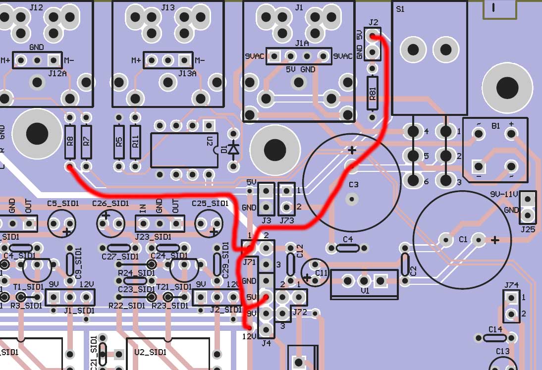
No, do not try PSU Option B. Basically you should have 5V at C3 "+" pin. Right? TEST IT! Connect this to the other places shown. Maybe you forgot to connect it to C3 "+" pin. Again I'm assuming the track between the power switch and C3 "+" pin is good. TEST IT! You need to actually do some troubleshooting for yourself now. If I say "connect a pin with 5V on it to J4" then that means you need to actually solder a wire and test that it is connected, not just report back "no it doesn't work". Use the continuity tester on your multimeter (or resistance tester) and test which points indicated by the red wires on my diagram are connected (i.e. ~0 ohms) and which are not. Including C3 "+" pin.
-
Let's start using actual part labels on the PCB... right-to-left this is U2_SID1, U1_SID1, U2_SID2, U1_SID2 etc. Thus there are four groups of two SIDs (right-to-left), U1_SIDx is the LEFT SID and outputs on the LEFT channel, U2_SIDx is the RIGHT SID and outputs on the RIGHT channel. Each pair of SIDs is connected to the PIC (U1_COREx) U1_COREx pin 24 connects to U1_SIDx pin 8. U1_COREx pin 27 connects to U2_SIDx pin 8. This suggests something wrong between U1_CORE1 pin 27 and U2_SID1 pin 8. "stereo channel switched over" doesn't make sense. The output of "SID 4" aka U1_SID2 will always be the left channel. The output of "SID 3" aka U2_SID2 will always be the right channel. This suggests something wrong between U1_CORE2 pin 24 and U1_SID2 pin 8. This doesn't match the earlier statement "SID 5: quiet but audible ("1/2 strength"), SID 6 - loud and clear." Let's assume you just mixed up the good/bad labels. This suggests something wrong between U1_CORE3 pin 27 and U2_SID3 pin 8. This doesn't match the earlier statement "SID 7 - loud and clear, SID 8: quiet but audible ("1/2 strength")" This suggests something wrong between U1_CORE4 pin 24 and U1_SID4 pin 8. I think you should focus on just one SID pair for now and fix that, it's getting a bit confusing trying to work out what is and isn't working when you lump all of the tests into one report. eg for the first two SIDs (U1_SID1, U2_SID1), it seems the audio buffers are OK, pin 27 on each socket to the audio jacks seems OK, so it's something wrong before there.
-
Yes, you say J73 has damaged pads/tracks and is probably the cause of no 5V after this point, i.e. at J4. J71 and J72 seem to be good if you are getting 9V at J4. So leave J71 and J72 alone. They are not the problem. Missing 5V at J4 is the problem, and is probably only because of a problem at J73. Solder wires as shown to connect up the 5V tracks which are not being connected due to J73 being damaged. The red wires also show what SHOULD be connected by J73 being bridged correctly... i.e. points which should be 5V for PSU option A.
-
Congratulations vc slime 800! I look forward to hearing more experiments :thumbsup:
-
That LCD cable looks way too short, but I guess it works. I like to have mine long, and "rounded", going up and around the CS PCB. You can see it in the photos. A longer cable will also allow you to open it up completely and still have the LCD connected, which is good for troubleshooting. I suggest removing the LCD from the CS PCB and testing it that way. Also ensure there are no shorts between the LCD's pins (where you soldered the cable) and the CS PCB. This CAN HAPPEN and cause buttons to work, maybe even making the backlight stop working. I insulate with sticky tape, but a piece of thin card or electrical tape will also work. Perhaps you should now try taking out the shift register chips on the bottom of the base PCB, thus disconnecting the two PCBs almost completely... and get to a known good starting point, such as, MIOS installed and the LCD working.
-
:thumbsup:
-
Try adding wires like this picture.... that should bypass any problems with J73 being totally stuffed. You may not need to do all these connections.
-
Don't worry about J3, it's only an optional 5V/GND output. Try soldering a wire between J73 pin 2 (or C3 "+" pin) and J71 pin 1. Also, to connect 5V to J2 (the header for the power LED), solder wire from C3 "+" pin.
-
P.S. I don't mind if people email me for help troubleshooting their sammichSID, but you can get help from other people (and quicker) if you post on the forum.
-
I don't think you need to see the torrent of emails I got from him :D It's fixed now, but I'm still not sure what happened, it was as if the PIC only had the bootloader and not MIOS installed, but I burn both into every PIC, and validate it too. Then he had trouble with his MIDI interface and couldn't upload MIOS even though MIDI In and Out were tested and worked fine (i.e. shorting Rx/Tx gave good loopback).
-
To start with, for the ones that are completely silent, you can try jumpering pin 8 of a known good SID socket with pin 27 of one you want to test. Also do the inverse (pin 8 of a "silent" SID socket to pin 27 of a "good" SID socket). This will help you validate that all the PIC->SID socket tracks are good and the problem really is in the audio buffers for the SID socket. It might also be a good idea to connect your amp or whatever to the J23_SIDx headers and validate the audio sockets are OK. Alternately, you could use the testtone app and connect SID socket pin 8 to the OUT pin of J23_SIDx with a 1K resistor (to be safe) and test the audio sockets that way... I haven't ever tried this but it should output a 1khz tone but probably not the same volume as through the audio buffer. It's possible that you've fried a few transistors, or maybe just didn't install components correctly. Check the polarity of all the electrolytic capacitors in those areas, and that the resistors are correct values.
-
No, you're measuring 5V correctly... pins labelled 5V should be +5V relative to GND pins, everywhere, for all PSU options. I think you overlooked my solution: The problem MIGHT BE a missing bridge at J73, which connects the 5V out of S1 to the rest of the 5V tracks on the PCB. It's the only explanation for 5V at the power socket and power switch and not anywhere else.
-
white on blue most popular? this is not normal, but on meth it is. come on... WHITE ON RED! MIT DAS NILSLOGO! IST GUT, JA! DU WILST ES!