strophlex
-
Posts
536 -
Joined
-
Last visited
Content Type
Profiles
Forums
Blogs
Gallery
Everything posted by strophlex
-
What about this one? http://www.conrad-international.com/?article=446009
-
How much of this is case and how much is panels?
-
I think it would be cool with a custom back panel and a front panel with the leds. The Thonnman panels wouldn't be optimal in my oppinion. They don't even have the right number of holes. 11 is needed. Are there USB type B connectors that fits into those round XLR-size holes available?
-
Which C64 power supply has the most juice / current ?
strophlex replied to Futureman's topic in MIDIbox SID
Any idea how much current will be drawn from the 9V? I think there was a 2A fuse in my supply. -
Which C64 power supply has the most juice / current ?
strophlex replied to Futureman's topic in MIDIbox SID
Any idea which ones are powerful and which are likely to fail? -
That's exactly what I meant would be nice. That solution would be good enough for me.
-
Hmm... I really want encoders with switches. Any way to make extra holes and traces on the pcb to be able to connect the encoder switches to HC165N on another board?
-
What about encoder with switch?
-
On the Mackie controler there is another LED below the encoder too, so that would be sweet for the MBLC too I guess...
-
This is comming along very well. The four in a row option seem best to me. It would be compatible with a classic MB-LC.
-
Share your early (not-so-great) works! (formerly your first one)
strophlex replied to Enth's topic in Songs & Sounds
Here is some nasty shit made in the year of our Lord 1995 using Pro tracker and an Amiga 1200. One of my very first tracks. Lo-fi and really lousy! http://www.2shared.com/file/4643440/8dae9cdf/03_Bloodthirster.html -
Now that I read your post again I see you wrote the LCD on Wilbas box. On the red one it is a orient display I think and that's the same as I have.
-
It is correct on the MB6582-side. The LCD side is dependent on your LCD. Check the data sheet. It was correct for my LCD and I connected it successfully using that guide. It is really good I think.
-
Looks nice. I might be in for eight for a MB-LC...
-
As far as I know there is no CS parts kit so far. The parts for the CS you need are rotary encoders, diodes (easy to find) and tactile switches. Then you need some screws and nuts, case and panels. Last but not least. Do you have PICs and SIDs? Did you check out this? http://www.midibox.org/dokuwiki/doku.php?id=wilba_mb_6582_control_surface_parts_list Good luck!
-
I did the exact same mistake on my 5x5 device... Will this be fixed in the final release?
-
After measuring some voltages I realized I have to turn the contrast pot to get 0V to get any text on the lcd and I would like to get some negative voltage to get it good enough. In the data sheet a Vopr=Vdd-Vlc is defined and supposed to be around 5V so it makes sence that I have to turn Vlc to 0 to get it working. Getting a slightly higher Vdd would solve the problem I think, but I guess that would cause other problems instead.
-
Hi I read in the MB SID V2 documentaion on ucapps that it doesn't matter if bankstick number 8 is 24LC256 or 24LC512 since it will only use 32k anyway. It would be useful for me to replace one 24LC512 for a 24LC256to get a spare for my MB SEQ. Can I just interchange U11 from 24LC512 to 24LC256 without degradation?
-
I got it working. Just ignored pin 15/16 and soldered the backlight power to A/C on the other end of the display. My only problem with the 2x40 displays now is that the text is weak. I turned the contrast pot up to max but it is still not sharp enough. I guess there is some voltage that could be raised a bit.
-
Good to hear there is progress behind the silence. Keep it up.
-
I soldered some 2x40 displays for my sequencer yesterday and ran in to an odd construction. In the datasheet it says pin 15 is A / B+ and 16 is K / B-. This gives me the impression 15 should be connected to B+ (connected to +5V) on the core. The problem is that when measuring in beep mode with the multmeter it is clear that pin 15 is connected to ground on the display. I tested this on a completly virgin display too, so that must be the construction. If I connect it this way around it result in a short cirquit. I tried before realizing this and got a really hot regulator :P. Anyway I got the display working without backlight with 15/16 disconnected. Who is stupid here, me or the manufacturer? I guess I am to stupid to realize I am stupid. There are connectors for A and C on the other side of the display. Can I use them to connect backlight volitage instead? Not a word from shopeio yet.
-
Thanks guys! I will try to get a new display from shopeio.
-
It is this one http://character-lcd-lcds.shopeio.com/inventory/details.asp?id=1287&cat=Lcds&sub=Character%20Lcd . Same as Kartoshka made a bulk order of some time ago. In the data sheet it looks like the connectors are the same as the example in the lcd module part of ucapps. So I think I have the right data sheet.
-
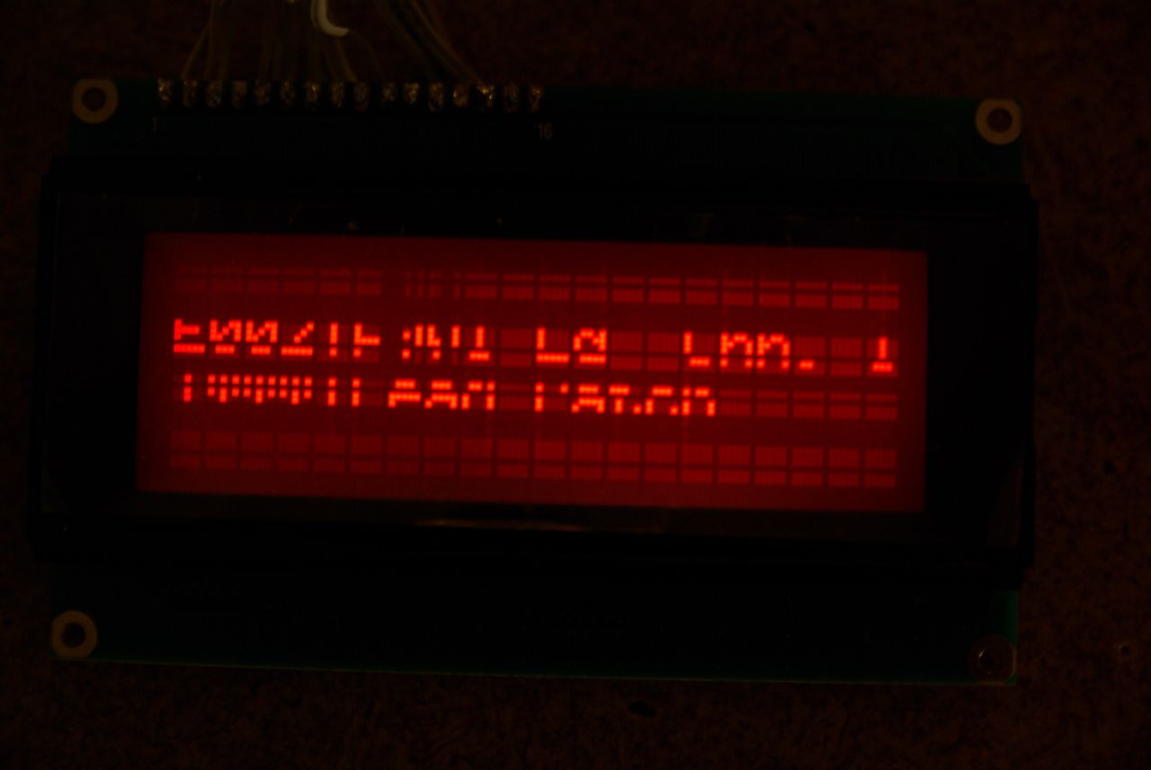
Interesting, what does that mean and how can I fix it?
-
Hi I just tried to set up my 4x20 oriental display on my mb6582 and get this uggly result. I have connected the display from my mb64 to the mb6582 and it looks good except that it is small. I have tripple checked the wireing and it is correct. I think the display is broken one way or the other, anybody has a better idea? Thanks.