

verpeiler
-
Posts
55 -
Joined
-
Last visited
-
Days Won
2
Content Type
Profiles
Forums
Blogs
Gallery
Everything posted by verpeiler
-
Looking for frontpanel for SEQ in Heidenreich case
verpeiler replied to verpeiler's topic in MIDIbox SEQ
Thank's for the tip! What I'm looking for is either the fpd file which fits the Heidenreich case or maybe a ready made panel. The fpd file I found in the Wiki seems to be not specifically made for the Heidenreich case. I prever a fpd file which is proven to fit into the Heidenreich case before trying to adapt Wilbas files to the case. -
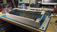
Hello fellow MIDIboxers, as I was out of the DIY stuff during the last years, I completely lost track. Now I want to finish my SEQ. I have a Heidenreich case laying around as well as a MBHP_CORE_LPC17 v1.0, the CS board from Wilba (the blue one, no revision printed on the board, just the year 2009) and also a MBHP_AOUT_NG R1 (but I don't think that it will fit into the case). To continue I need a frontpanel (and probably the backpanel). Could someone of you point me to the .fpd-files, please? Thanks a lot in advance!
-
Stephan Bodzin live @ Piz Gloria for Cercle
verpeiler replied to Antichambre's topic in Songs & Sounds
The PO10 has nothing to do with Midibox. PO10 stands for "Posing Controller Level 10". SCNR -
I'm looking for a rocker switch as well. You can find some at eBay from time to time (search for c64 switch, I think they will fit but I'm not 100% sure). Currently a seller in Germany has some of them, but 9 Euro for a used part... Have you seen Hawkeye's great Building the MB-6582 Control Surface - Photo Tutorial ? It's very helpful and contains part numbers. BTW: For the base to cs connections I would recommend to just follow Wilba's instructions and use the stiffy flat flex cable. It's more than sufficient. Once you are done you will open the case maybe 5 times. A detachable solution is always nice but not worth the effort.
-
 I like to build a similar enclosure. So I'm definitely interested how you solve it. Good luck!
 -
Looking for one or two Salecom T80-R rocker switches for a MB6582 build. Like this ones.
-
MidiboxShop/SmashTV SEQ parts kit question about resistors
verpeiler replied to keves's topic in MIDIbox SEQ
Have a look at this wiki page -
 The buttons are really nice! :) What kind of switches did you use?
 -
sammichSID Bulk Order Run #29/#30 - preorder form online
verpeiler replied to nILS's topic in Bulk Orders
Oh. Nice! Interested! -
I opened a similar some time ago. I have no fan in my MB-6582. Stuffed with 8x6582 I have no problems so far. But I will add heatspreaders to the SIDs next days.
-
Not sure if I understand what you have written. Do you get 5V at Pin1 of the LF33, or not? As ground I would use Vs at J2 or the metal parts of the USB or the 7805. From the pictures I would propose to reheat the solder joints of the LF33, they look ugly. Also you should reheat all other solder joints which look like "bubbles", as this is an indication of cold solder joints. Then try to measure at the solder side and also at the upper side! It's also a good advice to clean the board (see my comments in ) as you can distinct a lot better between good and bad solder joints.
-
Pin 1 is the Input of the regulator LF33. If you don't have 5V between Pin 1 and Pin 2 (Ground) you won't get anything out of the LF33. Maybe there is a short anywhere between the ground and the 5V lines? Could you measure the resistance between the Pins at J2? There should be no(!) continuity between the Pins Vs/GND and 5V. Could you post some pictures of your PCB (both sides, hires prefered)? Maybe some other pair of eyes see something.
-
Jumper J17 is set? Measure the voltage at the LF33 (IC7). You should get 5V between Pin 1 and Pin 2 and 3.3V between Pin 2 and Pin 3.
-
Since I created/initialized a "Session", the error message "SD Card Error !!! E 11 (FatFS: D 9)" does no longer appear and I can save settings like the Default Port. I did not know that the Default Port is saved in the session files. Unfortunately this took a while since the error message is a little bit too generic. I also had to learn that the session name "Default" is a reserved word for a "special" session. Once created, I can't delete it with the Seq (but I can delete the files with the Filebrowser). The other problems with MIOS Filebrowser still exist (upload works, download doesn't) but I guess this is a problem with my old Windows XP installation?! Now I'm learning how this thing works. Seems to be a very powerful and useful device. Thanks TK and Midibox folks!
-
No MagJack hence no OSC here, just some ideas... I would check basic ip conectivity at first. Is your core and your OSX at the same ip subnet? If so you could try to ping and/or verify your OSX has an entry in it's arp-cache for your core. You could watch if your OSX receives something from the core with tcpdump. Could you post the output of an ifconfig -an from your OSX and the output of the network command from your core?
-
I'am about to build a SeqV4 based on LPC1769. Right now the core is completely soldered and the Wilba-CS is soldered except for the encoders and LEDs. As I have no SD card adapter yet, I soldered an old 256MB SD card directly to a cable attached to J16 (means I can't put the card into my computer anymore). A FAT(16/32?) partition was already there and I copied the hwcfg/wilba/MBSEQ_HW.V4 in the root directory. The Seq doesn't complain about missing SD card anymore and is able to read the config file (which enabled the CS buttons). But when I change the config (e.g. changing Default Port from USB1 to OUT1) I get "SD Card Error !!! E 11 (FatFS: D 9)". I had to set "single_usb 1" in the bootloader otherwise MIOS Studio was unable to contact the core which was really strange as I received (for example) the Seq's system settings and the File Browser was able to upload files (shouldn't that mean USB Midi in and out is working?!). The File Browser is also only working partially. I can see the files at the card and I can upload files. But the download (or editing) of "larger" files doesn't work. A file with just 3 Bytes can be up- and downloaded without problems, but the MBSEQ_HW.V4 OR MBSEQ_GC.V4 for example can't be downloaded completely. MIOS Studio tells me "Invalid response from MIOS32 core during read operation!" but MIOS Terminal gives a "[FILE] Download of 22217 bytes finished." On the other hand when I test with the USB Mass Sotrage application the up- and download works flawlessly! Reformatting the card with sdcard_format doesn't help. Beside this I have the impression that the MIOS terminal also has some Problems with my core. Sometimes the output from the core seems to be incomplete. Can't say that for sure, as I don't know the expected output (maybe it's an idea to modify the interface to print something like "done" at the end?). But I during the troubleshooting I saw that the output was truncated in the middle of an ip-address for the OSC interface, so I guess that something is not ok. Unfortunately I can't test with another card as I neither have one and also have to order an adapter in China first (guess that will take 3 weeks or so). But before I go on with soldering and ordering panels etc. I like to make sure that this is not a problem with the core or somethin else. Any ideas? Thanks a lot in advance!
-
Like many others... I fill a little bit Isopropanol in a cup and use a toothbrush. Afterwards I use destilled water and let it flow all over the board. Sometimes I use a little bit of washing-up liquid (in German Geschirrspülmittel) in warm water, trow the PCB completely in the water and use the toothbrush again. Usually two or three repetitions of this procedure is needed. Then use paper and compressed air (or just blow it) or a hair dryer (heat level low) to remove the water. Let the PCB dry for some hours before powering up! But this is only possible with "washable" components! Resistors, capacitors, diodes, ICs and sockets are no problem at all. But you should avoid by all means to wash a PCB when mechanical parts like potentiometers, encoders, switches etc. are soldered as the washing will remove the lube insight those parts!
-
Like many others, I used a frontpanel based on Wilba's design for my MB-6582. The labeling/engraving of the left/right (or increment/decrement) buttons (< >) did not match the default settings in the firmware, as it was switched (pressing left button moves right) . So I changed it in the setup_mb6582.asm and recompiled the firmware. Before: DIN_ENTRY CS_MENU_BUTTON_Inc, 16+4, 1 ; **new** Select B button DIN_ENTRY CS_MENU_BUTTON_Dec, 16+4, 2 ; **new** Select C button After: DIN_ENTRY CS_MENU_BUTTON_Inc, 16+4, 2 ; **new** Select B button DIN_ENTRY CS_MENU_BUTTON_Dec, 16+4, 1 ; **new** Select C button I attached the modified .hex-file based on the recent version V2.044 for other users to save the recompile step. Maybe this can be done in the next firmware release (if there is any)...
-
I use 99.9% Isopropanol. In the past I bought it from a local pharmacy (expensive 10,50 Euro per litre). In Germany I can recommend http://hoefer-shop.de. I got 5x1 litres for only 17,- Euro (incl. shipping). It's even cheaper if you order more. First time I clicked on a Google adword link. Delivery was very fast.
-
Have an untouched TTSH kit (means the PCBs and the case from thehumancomparator.net) laying around since march and I don't find the time building it. Would sell it for the price I paid (876 Euro incl. shipping within EU). Pictures will be uploaded next days. PM me if interested.
-
As this thread is about the LPCXpresso board from Embedded Artists, does someone know if they changed the layout for the boards which are produced by NXP himself (OM13000,598)? http://www.mouser.de/ProductDetail/NXP-Semiconductors/OM13000598/?qs=sGAEpiMZZMvnfWYzRsH6EalhGIo7K5FV Would go the STM32F4 route, but I already purchased all the boards from SmashTV...
-
Hi, I'm looking for a SEQ V4L (case not needed/optional) and/or a LPCXpresso board in hardware revision A or B from Germany. Or does someone know where to get one of the old revisions??? Regards, verpeiler
-
Dear Santa I would like to be number 11 please... Quant. | forum name ----------------------- 2 | taximan 2 | JohnnieBee 1 | monokinetic 1 | Acul 1 | rvlt 2 | smidirin 1 | =FFW=> (1 | verpeiler)
-
It's a great pity that neither sammichSID nor sammichFM PCB's are sold anymore. But why? :(
-
Hi Jason, es ist in der Tat für Einsteiger nicht ganz einfach hier durchzublicken, wenn man die Historie nicht mitbekommen hat. Thorsten (der Chef hier) hat irgendwann 1998 die ersten DIY-Projekte hier dokumentiert. Das war ganz am Anfang nur ein Midi-Controller mit 16 Potis (den man damals nicht an jeder Ecke für'n Apfel und ein Ei bekommen konnte). Und mittlerweile ist das halt riesig und überwiegend modular gestaltet. :smile: Wenn Du eine Kiste mit Tastern willst, die dann per Midi mit einem Computer oder einem anderen MIDI-Gerät kommunizieren soll, brauchst Du erst einmal nur zwei Dinge: Ein Core-Board (siehe "PIC based Core" auf der linken Seite der ucapps.de-Seite unter "MB Hardware Platform") und ein DIN Module. An letzteres kannst Du dann 32 Taster anschließen. Die zwei Module werden miteinander verbunden und das Core-Board hat dann u.a. den MIDI-IN und Out für die Verbindung mit anderen MIDI-Geräten. Am besten nimmst Du Dir mal ein paar Stunden und ließt mal unter "MIDIbox Projects" im Archiv die Beschreibung zu einer MIDIbox64 V2 durch. Dort steht dann beschrieben wie so ein Ding funktionieren kann und aus welchen Modulen es besteht. Hope that helps.
