latigid on
-
Posts
2,524 -
Joined
-
Last visited
-
Days Won
149
Content Type
Profiles
Forums
Blogs
Gallery
Everything posted by latigid on
-

LoopA V2 Introduction, Features & Support Thread
latigid on replied to Hawkeye's topic in MIDIbox User Projects
Actually only inputs are supported, you'll need a converter to use CV/gate. In principle it could be done as all expansion headers are there. I don't think the software handles CV and there is not much push from our side to squeeze it into the current box. A bigger unit might work. On that point, this represents another Core with DIN MIDI onboard. We could consider other "stackable" add-ons for small synths or controllers. -
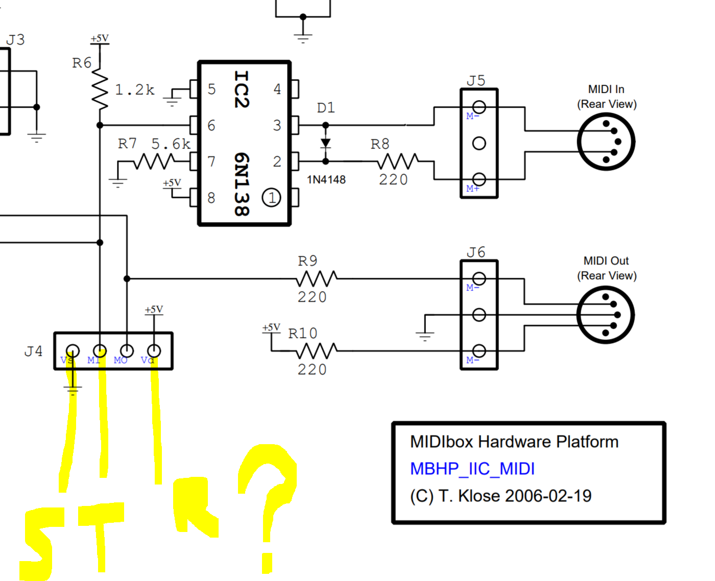
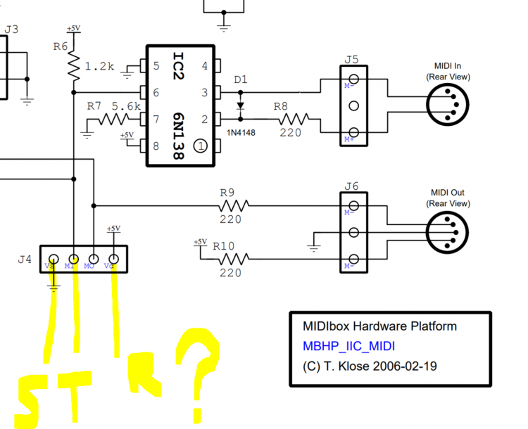
Generally try to provide as much info as possible here. This way the people trying to help you don't have to go looking though everything. The multiple info on this pedal or that and how these people do it isn't helping me help you. You have the schematic on how a MIDI in will work, you need to find out what your pedal does and how it supplies the +5V. Otherwise you need another power adapter to do so. My guess is that it happens with the ring terminal. Two options were provided to you to arrange the optocoupler on a known PCB design or a piece of perfboard/protoboard.
-
Shoddy work! Not only do they use a non-standard connector, they use non-standard wiring and make an external optocoupler necessary. What happens if you get the connections wrong and plug a 15V CV in there? How did you hope to power the optocoupler? Is there +5V on the ring terminal (measure with a voltmeter/multimeter)? I would assemble the parts on a piece of protoboard and mount in a small box. I thought the lump in the cable was an inline DIN female, meaning you could extend with a longer cable if you needed. If that's above you, you could use an IIC module PCB. I have one if you need or you could upload the brd file to OSH park. There, you could use a DIN female, the opto, diode etc. are already present, then connect jack to header J4:
-
I wasn't aware of the difference, I don't know much about micromatch. For the SEQ, it's very unlikely you'd need to connect/disconnect. If it was necessary, there's always the 0.1" standard pinheader, just a bit more effort and more clunky.
-
Hi Bruno, As the connectors are not intended to stack, I suggest to use paddle connectors on both of wCore/USB. Both installed on the top of the PCB and wired straight through. This works well as seen in Peter's video. Maybe other connectors are possible (?) but not necessary here I think. Does that answer the question? Best, Andy
-
another idea would be to use the delay on that track with triplet timing. Not sure about odder (1/5, 1/7) tuplets though.
-
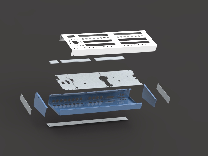
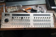
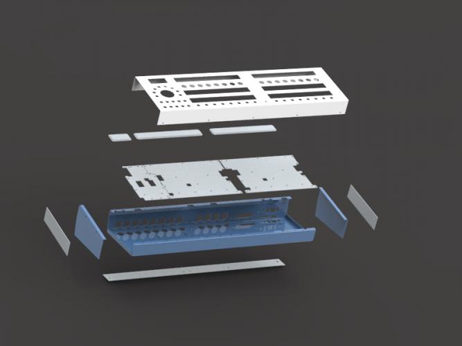
Assembly test of unpainted SEQ v4+ case , left handed jogwheel
latigid on commented on Hawkeye's gallery image in Members Gallery
 I think the LH version will probably suit righties better. It's also more like the Wilba version with groups/tracks on the left. The wheel is a bit different but honestly I manage without using it most of the time.
 -
Hi Bruno, The operation is quite different in that the group/track/layer buttons are now accessed through the Selection row. The selection row function is in turn switched by the 8 buttons around the larger wheel knob. So now you would choose Track; this gives access to the tracks on all 16 buttons. The Group structure (G1/2/3/4) is preserved to maintain compatibility. A big benefit is that multiple selections are now possible, which would have been quite difficult with the old workflow. Another benefit is that the Selection row can stay active while using the GP buttons above. Layers are accessed in a similar way. Hopefully the labeling is more intuitive now, and users don't feel limited to 3 layers of trig/para. Bookmarks are now brought out to the front panel. With the MEC buttons, there's functionality not explicitly present in the v4 (e.g. Live). Also, each encoder has an independent switch, so no one should run out of buttons. Normally the switches would be assigned to acceleration though. Maybe Peter can fill in anything I've missed. Best, Andy
-
You can plan for around 700€ all up, including the case and Mouser order. Not fixed yet though. Best, Andy
-
I'd say as these are built for guitarists rather than MIDI nerds, it's more than likely that there's sufficient protection built in. If the signals are around the wrong way it will not work but probably will not harm the unit.
-
I'm not confident I can work it out from the vague description; it's not your fault. MIDI is a current loop and the cables are passive. Normally resistors would be a good idea if you don't know what's what, but in this case they might hinder the operation by limiting the current. If you don't mind taking a risk or two, try the orientation you describe and swap it around if there's no joy. For a MIDI in, normally the 0v (ground) pin is not connected at the port. So you may wish to leave the sleeve of the TRS plug disconnected. Leave the pin two of the DIN connector connected to shield the cable. You're free to use a male DIN or even cut an old MIDI cable apart to avoid using a female adapter plug. Best of luck, YMMV etc.
-
I don't like the idea of combining MIDI in and out on one 1/4" jack. It's just another variation on the standard that will confuse. TRS 3.5mm jack with individual signals is bad enough :). What feature do you wish to use? I.e using the MIDI in of the Strymon? Or sending the MIDI out from the Strymon?
-
Cool development! If you like, I still have some of the USB PCBs around (maybe res-SD too). All wCores come with the USB attached; there's no current plan to sell them separately.
-
The matrix works fine :). The software is not yet optimised to work with the "inverted" sink driver.
-
Adrian is getting the last details of the case sorted. Don't know about you, but I'm impressed!
-
uploading MIOS to PIC18F4685 over midi ?
latigid on replied to goofyfirehydrant's topic in MIDIbox SID
You could try. First connect the MIDI out to MIDI in (loopback test). http://www.ucapps.de/howto_debug_midi.html -
uploading MIOS to PIC18F4685 over midi ?
latigid on replied to goofyfirehydrant's topic in MIDIbox SID
Hi, welcome Yes, MIOS Studio should be used to upload hex files for your SID app. First, the MIOS Bootloader should be burned onto the PIC. http://ucapps.de/mios_studio.html http://ucapps.de/mios_bootstrap_newbies.html Find a list of suitable interfaces here: http://www.midibox.org/dokuwiki/doku.php?id=midi_interface_whitelist Typically avoid those on the blacklist, including a lot of cheap USB-DIN plugs. -
16x8 LED matrix works well!
-
There's only one micro port on the DISCO board :). If you don't have a "special" USB OTG cable, connect pin PA10 to 0v (ground). On the wCore, this is accomplished with a USBA port and a dedicated switch to enable host/slave.
-
Enc plates I think are unchanged since v1.0. Perhaps some diodes were moved around to lessen the chance of accidental shorts. le mec is now at v1.3. Basically unchanged but some differences (mostly to do with minimising ghosting).
-
As far as painted keycaps go: it could work. I spent weeks emailing trying to get painted caps, but they would have been fully painted and much more expensive. So the idea with model train paint could be cool! Personally I love the look of blank illuminated keys:
-
We could still label the Matias switches e.g. between the Matias rows. As you mentioned, the "GP" labels are printed on screen anyway. The selection row does change its function, and not all functions are 1-16, e.g. for selections regarding tracks, the group terminology (GxTy) is still used. Personally I quite like the "clean" look without extra labels. Regarding brightness, Peter has gone for a fairly bright incarnation. If it was too much, you could easily increase the RJ values to limit the current. Personally I don't find the brightness too bad with 49R9s in my build. There are two further options that might help. First, we are ordering a set of relegendable switchcaps. These won't be available for some time, but could be a type of upgrade. The cost will be more than the default DSA clear (which by the way have some diffusion on the top of the cap), as each cap comprises two parts. Then all Matias switches could be independently labeled. Second, you can choose the colours of the step LEDs. Notice on TK.'s demo that positions 1/5/9/13 use a different step colour to the rest. This might help to differentiate them. Best, Andy
-
Did you check the soldering/flux residue around the pins that control the display?
-
It could be a dud display injecting bad vibes onto the SPI, it could be a defective chip or flux residue.
-
Relocation of keybed from main board not working
latigid on replied to Gregmidi's topic in MIDIfication
Also this from Reichelt: https://www.reichelt.com/de/de/wannenleiste-20-pol-stifte-din-41651-3m-46206001-p224961.html?&trstct=pol_4