latigid on
-
Posts
2,524 -
Joined
-
Last visited
-
Days Won
149
Content Type
Profiles
Forums
Blogs
Gallery
Everything posted by latigid on
-
Interesting. What are we listening to exactly?
-

Full 16x16+X BLM with silicone buttons, matching case. Interested?
latigid on replied to latigid on's topic in MIDIbox BLM
Hi Jack, I have to think about that, but for the moment you can follow the connections on the schematic: http://www.ucapps.de/mbhp/mbhp_blm_map.pdf I'm here and I will help you. Please use the build thread or PM with specific problems and we'll get to the bottom of it. Best, Andy -
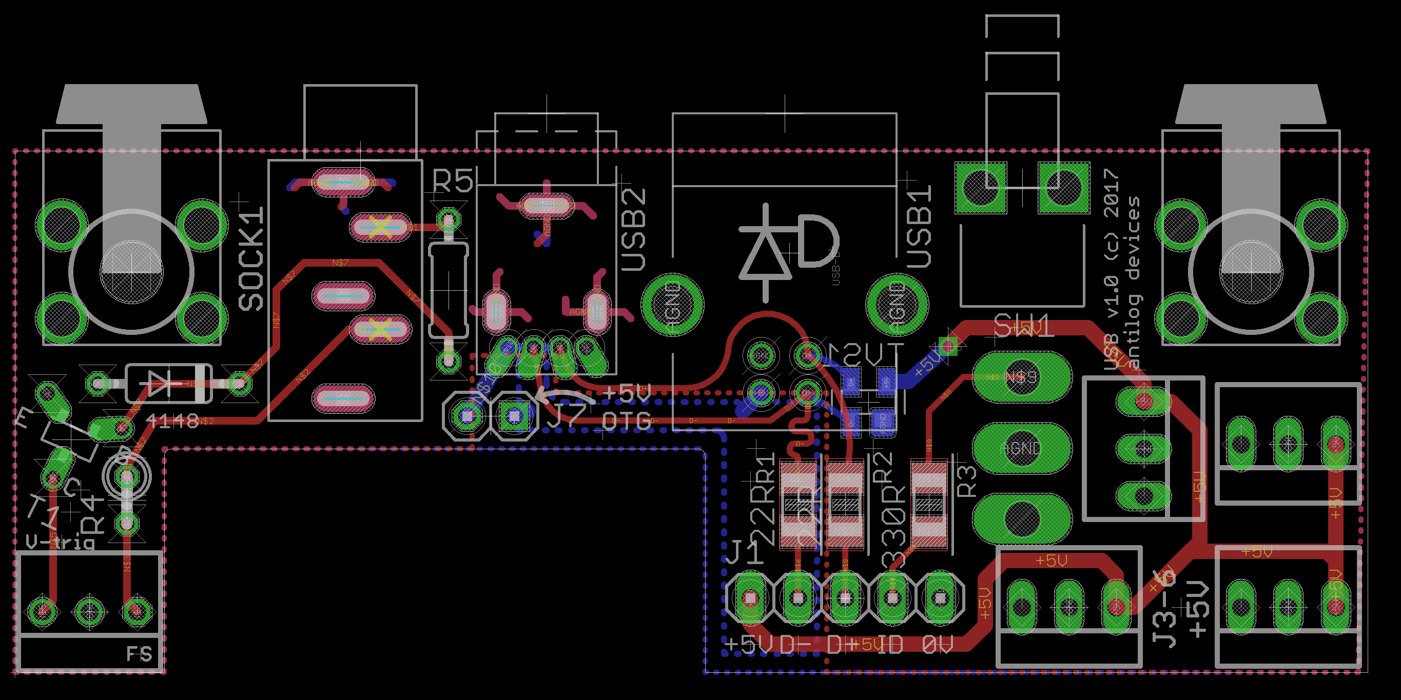
This last order had 11 different PCBs in it and includes everything needed for a SEQ, like the MIDIO/I2C/line transmitter and also a new design for a Core that doesn't rely on the Discovery board. The USB entry module had some fab issues, because it's not clear how to call out plated slots: (the thing to do is to give the actual cutout of 0.8mm min. width in a separate file, not just the router path as I've seen before) But hopefully they'll be on the way soon. The subsequent steps will be to build and test to make sure it's all sound, then send a set to AdrianH, so he can work on the case once all of the heights/dimensions are known. Of equal importance is to get TK. on board, as this is three different BLMs that will need updated programming and HW config files. He is extremely busy this year but if the past is an indication, he will give a bit of his "vacation" to the project. Otherwise I'll take the train to Munich and sleep on his doorstep :P. Hopefully things become clearer in the next month or so. If all is well I can start to take orders, although I may have to look further as the forum is quite quiet at the moment. @gerald.wert No problem! I spend the time on these projects when I can because I want something nice for myself, and I also want to do good by those who want to take part. But this is MIDIbox, and if you have the time and motivation, everything is there to build your own custom unit. Best regards, Andy

-
@borfo I've already ordered the boards a few weeks ago, so this is a bit moot. But I've had some thoughts throughout the day. IMO, there's not much point in breaking out the matrix further for individual button wiring. Like you say you could design something to work with or replace a DIOMATRIX, but you'll still find work needs to be done on the switch side. Instead you might find it's easier to use DIN/DOUT modules instead and forget the matrices. One of the goals of this design was to use high-quality switches. The Matias ones are rated for 50M key presses; I don't think you could say the same for the Chinese ones. The latter are only single colour, so the improved features wouldn't be implementable. It's a huge pain to find illuminated switches at reasonable cost, and I've put a lot of time into finding a solution. Matias switches cost 0.25 USD or less, you do need a custom keycap but their price will depend on the quantity. Should be around $1 each for switch + cap = $32 per SEQ. IMO that's not a bad price and the HW should be commensurate with the amazing software TK. provides. @gerald.wert Personally I wouldn't trust those switches, and you'll find even bi-colour switches are very hard to source let alone RGB. You might fit some kind of SEQ in a C64 case, just keep in mind the LCDs need around 360-70mm, and you probably want some kind of datawheel.
-
Great, but maybe you can be more specific? I can't see how your +5V connection was missing, apart from cold solder joints, but you said above that the soldering was fine.
-
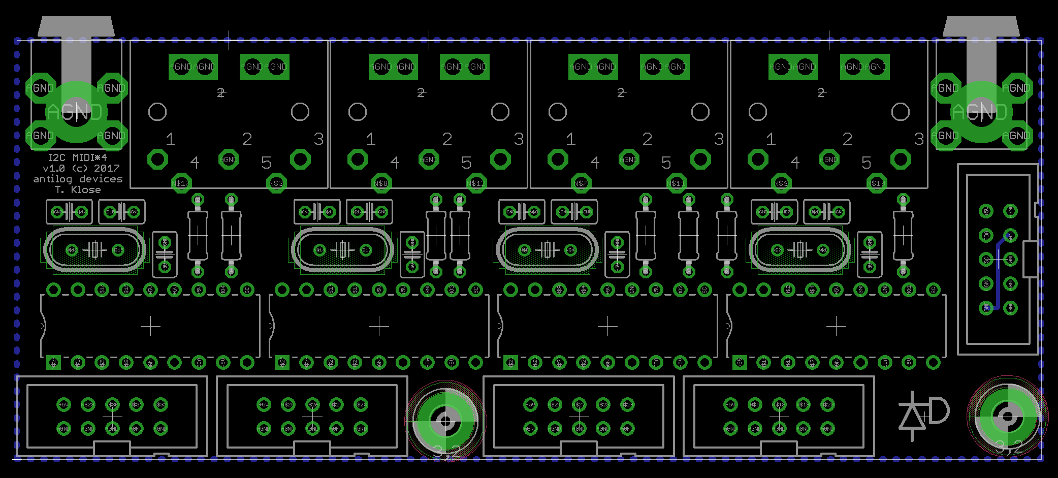
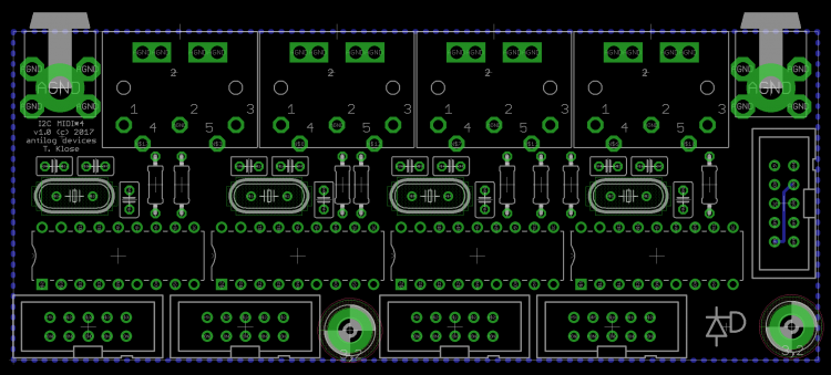
Have you already cut out the rear panel? If you're interested, I have a board at the fab at the moment: It's 107.5mm across with 21mm spacing between the DIN5s. Still needs to be tested, but the alternative is there. Best, Andy
-
J2_SI is only required if you connect some sort of DIN chain to your Line sender, and you need to get those data back to the Core. But it doesn't matter if it's soldered in place for your case. If you look on the uCapps page you can see the situations where the configs are explained. Good luck!
-
You assign a whole SR to 8 gates (or clocks/triggers etc.), so the two from your AOUT modules will be replicated. CV_GATE_SR1 3 is what you want, assuming the line driver is connected to J2 of the Wilba PCB.
-
Good that it's working. What was the exact issue for the benefit of future travellers? Backwards RNs?
-
... diodes could be backwards or missing...
-
The ones you linked are the correct type, as long as Reichelt delivered the correct ones. There are two (well three, but dual terminator is not so common I think) types of RN, one where the pins are isolated into individual elements, the other has one common/bussed connection and are used for pull-up/down resistors. A picture = 1000 words. It can save a lot of time for those helping you troubleshoot to check if your soldering is sloppy, maybe the switches you used can be installed sideways etc. etc.
-
The question of course is whether you also used isolated networks for the CS as well as the Core?
-
Nice green machine! http://mutable-instruments.net/forum/discussion/8485/tsfkaa-pro#Item_19
-
For completion's sake, did you get the ST7066U LCD working? Btw, these threads aren't a waste of time, as there's a lot of good troubleshooting tips. Could be a useful entry for the wiki?
-
The datastream for WS2812 is serial and runs separately to J8/9, so matrix events don't make sense. Instead, each LED needs its own EVENT_RGBLED. The current _NG implementation can either change the hue (colour) or the value (brightness) when dimmed=1. Let me know if you want some PCBs and/or encoders. Best, Andy
-
You can jury rig a 4x 1k network pretty easily It might go better on the rear side of the Core?
-
Normally if you can get communication going over USB, the LCD should boot up with either "READY" or a start screen from the application. Is your resistor network soldered the right way around? How long is the cable for the LCD? photos photos
-
I'm wondering if the transistor is correctly installed or has a non-standard pinout.
-
Is the voltage set to the proper value (probably +5V)? Is the chip 74HC595 or 74HCT595? Did you try swapping the chip? Is it a real Discovery board or a cheap clone? Decent pictures would help in troubleshooting
-
Some other ideas: make the track divider very long, so the retrigger occurs after a longer time set the gate length to full (glide), wait for the step to play then remove the step (or mute the track?). Perhaps the note off event will not be sent in this case.
-
Did you try fiddling with the Glide trig layer?
-
^^ these are very nice troubleshooting tips @gerald.wert! A bit of info can be gleaned from the following MIOS code: http://svnmios.midibox.org/filedetails.php?repname=svn.mios32&path=%2Ftrunk%2Finclude%2Fmios32%2Fmios32_lcd.h a "stab in the dark" test could be to load the bootloader hex (through MIOS Studio, not using the boothold mode) and change for one of the following LCD types: MIOS32_LCD_TYPE_CLCD = 0x00, MIOS32_LCD_TYPE_CLCD_DOG = 0x01, MIOS32_LCD_TYPE_CLCD_PP = 0x02, only the 0x00, 0x01 or 0x02 are needed.
-
You might try some of the other LCD configs, though I couldn't say what one would be better. For the SD card, one way is to edit the file with a text editor on your computer and upload it using the file browser. Normally uploads go okay, but downloads hardly ever work for me.
-
Design concept - control surface for VST plugins
latigid on replied to ChinMuzik's topic in Design Concepts
Of course, I asked incessantly if they could add switches, but because of the design that isn't possible. The workaround is to use individual metal touch sensors, which is a bit different but is quite easy to get used to I think. -
Yep, I've tried jam mode too and liked it quite a lot! It's my hope that the 16 selection buttons can be used in a mode to jump to different sections of a song for freeform restyling.