

Hawkeye
-
Posts
3,636 -
Joined
-
Last visited
-
Days Won
36
Content Type
Profiles
Forums
Blogs
Gallery
Everything posted by Hawkeye
-
Hi there, just a few answers: * there are two LED output matrices (both using 8x8 LEDs), see dout_wiring.pdf and there is one tactile switch input matrix (see din_wiring.pdf) * one of the output matrices is used for the visual 8x8 "mod matrix" on the cs6582 pcb, the other matrix is used for all other leds on the frontpanel * the JD? headers in the wiring diagram correspond to shift register outputs or inputs, just trace them on the baseboard * if you don't want to have the "mod output matrix", just don't connect anything to jd6 * jd8 is the shared "column strobe/pulse", you can think of each matrix as of one "column" being actively pulsed at a time, this pulse is used for the two output matrices and the input matrix simultaneously (i did not know this before, quite cool! :-)). * for the output matrices, you don't need ground, there is a direct connection between the JD pins that will feed the LEDs * for the input matrices you just have to provide ground to every switch, how you do that should be irrelevant, as long as it is all connected together. * if you want the same pin assignments as in the mb6582 hex, just trace the pins of the JD? lines to the respective component, eg the LFO1 LED would be "between" JD8, Pin D5 and JD7, Pin D4. Hope this helps? Many greets, Peter
-
MidiBox Cool Diy Device But Only For C-Code Experts
Hawkeye replied to zener's topic in MIDIbox HUIs
Hi Zener, MIDIbox is not just a platform for builders and coders, there are some very cool finished projects built upon it, and they are "ready for consumption" without any further coding necessities, e.g. * MBNG: just as Zam said, it is completely customizable, just by editing text/script files and it is really very powerful! I'd also like to add, that if you want a "generic" MIDI controller, a lot of functions are necessary, from SysEx stream parsing, to supporting multiple hardware user-interface element types (encoders, potentiometers/sliders) and so on. The result necessarily is "complex" by definition - and if you want to master it, you have to dig deeper. But if you do that, the rewards are huge. If you like to experiment with never-heard-before synth sounds, nothing beats the experience of having a huge hardware controller attached to your good-sounding-but-limited-control-surface synth. * MBSEQ: TK. has an open ear for user enhancement requests - if they fit in the "general scheme of things" or multiple users want "that one feature", he usually just implements them, just look at the revision log! * And a lot more, have a look on ucapps.de ! So, for the modern MIDIbox projects, you "just" need a bit of patience, some soldering experience (or a friendly helper for that), the knowledge of the C programming language is optional. Many greets, Peter -
If you can do it in MBNG (i have not done it yet!), you can do it with this unit too. The Programma will always be just a "unified" extension to MBNG with a "standardized" hardware set, so people can start exchanging templates for their synths. Many greets, Peter
-
Better between SCLK line and GND, you are using 4-wire SPI, right? Many greets and good luck! Peter
-
Admittedly, it has seen its up and downs, but it is not dead, yet :) In fact, i use the prototype really often for some synths, most often for the Moog LP and quite often for the Ensoniq ESQ-1, and came to the conclusion that it is absolutely necessary to have a good hands-on (the i-pad is not sufficient for me!) controller for most hardware synths (as the manufacturers often focused on the sound engine and had to limit costs of the control surface). Of course, Behringer had a nice offer with the BCR2000 here, too, and it is impossible to compete, cost-wise the Programma is unfortunately in a very different league... Hopefully, we will have a re-iteration with publicly available boards and a special MBNG version tailored to this specific hardware revision, so that it gets easier to build and set-up. Andy (who created some new boards a while back) is not yet totally burned out from PCB design, so we are somewhat confident, that there will be more to come :-). Have a great evening! Peter
-
[S] TPD (Track Position Display) full kits for sale
Hawkeye replied to ilmenator's topic in Fleamarket
It shows the relative position of each track, just like a progress indicator in the software world :). E.g. if you have a 64-step track, and the the TPD LED of this track is in the middle, the track playback position is also in the middle of the track around step 32. Quite a few years back, I made a very cheesy demo with the camera aligned on the (then very new) prototype-tpd, which should show what is going on: Many greets and enjoy! Peter -
Yes, if complete vertical lines fail, this is most likely the display itself. Then, on the other hand, the displays are fortunately not so expensive and it would be far worse to debug the MB6582! Many greets, Peter
-
Very cool then, please keep us posted on your findings. Probably using a 50R resistor and 100pF or so would be a good try, in addition to my 22pf solution, as many people recommend it :) That almost certainly sounds like a RF-induced problem. Long time back in the last millenium, we had some strange network problems in a then coax-wired 10mbit environment. A local network guru came by and asked us: have you put the Arnold on? Well, we did not know what he meant. Only a few minutes later he said, still grinning: Arnold=Terminator!!! :-) Yes, ok, it was a reaaaaly bad joke, but he was right, we forgot one of those tiny screw-on coax terminators, that should basically do the exact same thing as our OLED clock termination... and our network problem was solved :). Have a good evening! Peter
-
Hi Chris, well, the "antenna" effect of the wiring is why it happens at random, any kind of rf signal could be picked up, e.g. if you have a 433mhz garage door opener, try to hold that close to your OLEDs while operating it, and I'd be quite sure, you can trigger the effect instantly, if segments of your wires are about 20-30cm long :). Or (and that is mean), a switching psu that is nearby can cause it, they quite often emit RF, that will be picked up by those lines. It needs not even power the MIDIbox, but can power a different synth/unit. I once had a very noisy 5V switcher, that completely killed nearby GPS reception (other usecase, no MIDIbox). Regarding that my problems were only almost solved: yes, it still happens to me (the exact same display shifting effect you are also experiencing), but only once per evening session or so, earlier on, it happened after 5 minutes, but i am sure, that is because i put 24 displays on the same clock line (unbuffered) and the wiring is very long (i'd guess at least 1.2 meters!). Just try it out, if it does not work, only a few cents for the caps are gone and then you can investigate the "proper" buffering solution. Andy did quite some research there and has built an experimental buffer board already, that you could try out. Many greets, Peter
-
No problem, and yes only a single cap! It nearly solved all of my problems on the V1 programma and that has some very long lines to the displays. I've therefore not spent any more time on the issue, but an additional software solution might be to reinitialize the OLEDs while MBNG is running, e.g. when a bank-change occurs. That way, a garbled screen could be cleaned up again only using software. But it was not necessary, yet. I've experimented for a day or so to find good end-of-line termination, including resistor, excluding resistor and in the end, the resistor made no difference in my usecase and i ended up with a single 22pF ceramic cap on the last OLED between CLK and GND, it is so flat, you can solder it on top of the OLED. Before doing that, i stabilized the voltage supply to the displays (3V3 linear vreg), which was necessary, as i had been using only the tiny 3V0 onboard regulator of the disco board, which was overloaded after 12 displays or so, but if you are using 5V, probably it is no problem. Regarding the terminiation capacitor: you might need to experiment with the value there, as it depends on your setup and the "line length". If the cap has a too high capacitance, it will draw too much current and will "kill" the clock signal (I'd say no damage can occur, when experimenting with the value, you just won't get any output), if the capacitance is too low, no termination effect will occur, but i'd guess if you try out a handful of different values around 22pf, you will get a huge improvement. Edit after your edit (hehe): yes, by all means try higher capacitance values as well (or even try with an additional resistor as often recommended)! I might also not have found the best possible solution, but it was good enough for me. Many greets and have a nice weekend! Peter
-
Hi Chris: I'd recommend to try out the clock line termination first, with "only" 10 displays it may already solve your problems for good. And you only need a single small cap and can solder that directly to the OLED between CLK and GND. If you google for "clock line termination" and "ac termination", it is a common problem and addressed by many papers. Regarding buffering and inline-termination, Andy is the person to ask, he made a circuit for the programma, but we have not tried it out yet. Many greets, Peter
-
Hi Chris, had the same problem with the Programma (24 OLEDs of the same type). I had the impression, that the length of the signal lines (especially clock) is a problem, installing a small ceramic capacitor (22pf or such) between clock and ground at the OLED at the end of the chain solved a few problems, as well as adding good power supply (3.3v linear vreg), but in the end, buffering might be necessary. The problem is, that the OLEDs themselves might "talkback" into the data lines and especially the clock line, and the more you have, the worse the signal gets. TK. recommended buffering to me, when i talked to him about it, and i think he is right (as usual :-)), the problem should go away, if there are only very few OLEDs or you are using very short data wires, or are using termination (like described). Andy also came up with a nice "inline termination" and buffering idea a while back, this will be worth a try and you need not modify anything on the display boards. An explanation: the long data lines act as kind of "antennas", this also explains why the problem is there on one day, and you have no issues at the other day. Without termination, then part of the signal at the end of the line is bounced back into the line, further degrading the clock signal. Many greetings, Peter
-
Samplers, yummy! :-) While there are a lot of really nice bigger units (i love the Roland V-Synth for sample bending and unreal time-processing, but it is not a "classic" sampler) and the E-MU E6400 Ultra (really great user interface, full MIDI control, 64 channels, classic sampler with lots of memory and a nice disk subsystem via scsi2sd), for your usecase (portable and small), a newer Elektron unit comes to mind: either an Octatrack or one of the new Digitakt machines! They are small and portable, have modern storage, inbuilt FX and sound good. My recommendation: watch a few Octatrack or Digitakt demos! :) (I personally also own an Elektron Machinedrum UW (their predecessor, also a 12-bit engine), including user sample storage on internal memory, it boots fast, and is great to use, but sample transfer is not so brilliant. But then, it makes you think about what samples to use before using them, so not too bad at all.). But, don't let me hold you off from Bruno's modification proposal of the S-760, that sounds really awesome and would result in a totally unique machine! Have a great weekend! Peter
-
No problem and thanks for the thanks :-). There should be some 2mA "low current" LEDs out there, that are fairly visible (only low current requirements for relatively good illumination), so these would be nice in a 8x8 setup. And then, you can probably leave half the matrix open on each individual board, to have a 4x8, that is controlled like an 8x8 from the SEQ. If you are not afraid of hacking a bit in C, it should be fairly easy to reduce the matrix from 8x8 to 8x4. Problem (i have not checked the source), i don't know if you can enable multiple matrix setups, so check that first. As all of this is a bit complicated and as you want brightness, let me suggest something else: go for direct DOUT wiring (no matrix) on each individual board. If you only have 32 LEDs on there, this is easy with 4 DOUT shift registers, in a medium sized SMD package, these are easy to solder and won't take lots of space, it would even be possible with through-hole shift registers. just my 2cents, you have to experiment, but in the end, that is what MIDIbox is about, learning and having fun... Many greets, Peter
-
Yes, with a bit of hacking you can do that easily, but the default for the SEQ is 8x8 for Wilba's variant. From a developer point of view, it makes only sense to support frontpanel variants that are built in larger quantities (like Wilba's panel and soon Andy's new panel). But as the SEQ is fully open source you are totally free to modify it to your heart's desire, you just have to keep maintaining it, when new versions are released. If you ask for my personal advice: go for an 8x8 matrix with low-current LEDs, it is easier on the long term. But the 4x8 variant is a nice learning experience, too, i don't want to discourage you. Many greets and have fun! Peter
-
Yes, 25% duty cycle in a 4x8 matrix, but i think MIDIbox primarily supports 8x8 and these are fine generally, you can drive 64 LEDs with only 16 shift register outputs, which is very economic. It just needs bright LEDs, so better test them, than to believe in datasheets :-). Also, i might have an explanation about reduced brightness, when all LEDs are on: the shift registers generally only support 20mA output per pin, so these 20mA would be shared amongst 8 LEDs, if all are on. Totally ok for low-current LEDs, but it might be dim otherwise. Many greets, Peter
-
Yes, it will work technically, but you should test the brightness before committing to a special LED type/manufacturer. You can do this manually just by testing a bit on breadboard. LEDs may vary in brightness and i would not rely on mcd values stated by the manufacturers... Better to test early, than to be sorry later on :-). For the Programma, I also tested the green MBLREs LEDs before soldering them in, with and without the ULNs (same as SEQ in this case). While it worked without ULNs, the brightness was visibly reduced without the ULNs, but only when all LEDs where "on" (maybe I hit a current limit somewhere). But: it depends on the number of LEDs you are driving, and especially on their type, so do test them and don't shy back from "low" current-limiting resistor values like 47R, even if they would produce high LED currents on paper... what counts in the end is the average current flowing. With only 1/8th (or 12.5%) on-cycle-time, that will be low anyways... so you should get low-current LEDs. Some people also successfully direct-drive matrix-connected LEDs, with low cycle times (0R current limiting). Many greets and good luck! Peter
-
OLRE16 with Lattice CPLD as Clocking/Addressing interface
Hawkeye commented on Antichambre's gallery image in Members Gallery
 Man, it looks awesome! Very well done! :-) Many greets, Peter
 -
Hi u-link, yes, it is on the medium-term list, Andy has created nice PCBs with the exact same OLEDs, but with RGB-backlit encoders (which saves space in comparison to the LED rings, and also adds a bit of "improved readability" because of the option to have different colors for different sections of the controller). But, currently the new MBSEQv4+ is in the central focus, so the availability and build-documentation of these boards comes first. But there is a good chance for MBProgramma availability (and documentation) somewhen in 2018 (rather later than sooner in the year, as it is a complex project). Many greets, Peter
-
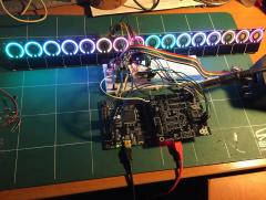
Here is a quad MB-LRE8x2, 1024 green LEDs (green = rather problematic, currently don't know the mcd rating though), 47R resistors, ULN drivers. Brightness is more than fine: Just try it out with a test build! Many greets, Peter
-
Nice! That JP8080 sure is a very cool synth! Many greets! Peter Edit: the sound is really nice & good for coding! :-)
-
Displays not initializing after working for a while
Hawkeye replied to EvilEvilEvil's topic in MIDIbox SEQ
me needs a coffee, too ;-) <detective_mode> Good catch! It makes a difference electrically, that's also what TK. saw and why he posted his cable pictures, methinks. The cables are ONLY valid, if the connector housing arrow(notch) on both ends points e.g. to the red wire, but to complicate things, it does not matter, if one connector is turned by 180° to make an "s-type" cable or not. The reason behind that is, that you can bend the cable by 180° around the plug and the upper wire will always stay the upper wire, that's why you can optionally mount the plug strain-relief or not (which bends the cable by the same 180°), the wiring will stay the same. And you are right, in Evil's first picture (your first quoted picture) above, the notch of the cable plugged into the display clearly was not to the left of the screen, and that's what TK. also saw, methinks. It must look exactly like TKs picture (your second quoted picture), so this might be the reason, why the display got burned after some time of flawless operation in the first place, when it was plugged in again. Evil: it is not sufficient to just "rearrange" cables, you might have burned all displays, that were plugged in that way. </detective mode> ;-) Many greets, Peter -
Displays not initializing after working for a while
Hawkeye replied to EvilEvilEvil's topic in MIDIbox SEQ
Fully agreed with the oscilloscope, there are DIY kits for ~20$, that would be sufficient for the job, so this is no excuse anymore :-) -
Displays not initializing after working for a while
Hawkeye replied to EvilEvilEvil's topic in MIDIbox SEQ
Thanks for the super fast measurements, slo! Awesome! This would confirm my doubts about all data lines being "high" (rows 4/5 in slo's table, which are all 5v on Evils measurements), this might be the problem. Evil, I'd suspect maybe an accidental "bridge" to 5v somewhere on the core or a faulty 595 (maybe inserted the wrong way around??!?). As you said, that you have a second core, can you install the seq firmware on that second core exactly as you did on the first one and measure again, and see if the voltages are different? Edit: also please check the correct value and alignment of the resistor array R33a/b/c/d (i think Bruno recommended to check this, first)! 2nd edit: yes, the resistor array could be the cause, and maybe you soldered in both in the wrong alignment on both cores? You'd own Bruno/Antichambre a beer, then! ;-) Many greets! Peter -
Displays not initializing after working for a while
Hawkeye replied to EvilEvilEvil's topic in MIDIbox SEQ
Andy: probably he listed the MIOS dump to show, that the LCD type is set correctly (need to zoom in the second screen to enlarge). Regarding the J15 voltages: I've never measured all voltages on J15, but what puzzles me, is that the voltages of DB0-DB3 (the four data bus pins) are all "high". But maybe this is the default state in 4-bit mode, i am not sure about it, but it looks strange. It sure would be nice, if someone with a core lying around could confirm those measurements, i unfortunately just have no time right now... :-/ It is really a mystery! Many greets, Peter