

Hawkeye
-
Posts
3,636 -
Joined
-
Last visited
-
Days Won
36
Content Type
Profiles
Forums
Blogs
Gallery
Everything posted by Hawkeye
-
Mb6582 plus 4 SSM2044 VCFs - use of a passive 4 channel stereo mixer?
Hawkeye replied to Hermes's topic in MIDIbox SID
Addendum - had a little intermezzo with some opamps a few weeks ago ´cause I needed to repair a mackie mixer channel strip with a dead one... it is not difficult to understand how it works even for an electronics noob like me... for line-level sources (no mic-preamps, no eq stage) a simple active mixer is quite easy to create. Best regards, Peter -
Mb6582 plus 4 SSM2044 VCFs - use of a passive 4 channel stereo mixer?
Hawkeye replied to Hermes's topic in MIDIbox SID
Hi, imho this is not worth 50 bucks for just four 100k pots and a few sockets... you could just use the same passive mixer design as in the MB6582 - use 10k resistors on every channel and chain them together, it is good for 8 channels and should also good for two times 4 channels (just try it out) best regards, Peter -
Hi Ciro, looks like you don´t have MSYS "Unix Tools" installed. They provide what it is necessary for building the stuff. Look here under "Required Tools": http://www.midibox.org/dokuwiki/doku.php?id=windows_toolchain_core Best regards, Peter
-
Yes, it stays the same - I navigated to different patches meanwhile and came back to verify... Are you sure you didn´t just "upload to buffer"? It only stores the patch in "volatile" memory, in that case you need to save it manually from the MIDIbox... The other upload method ("upload to memory") directly writes to the bankstick and it should be conserved there for some time... Best regards. Peter
-
Hi there, first of all, thanks for sharing the patch... As far as I´ve understood in Multi Engine Mode (I don´t use it usually :-)), there are no single oscillators configurable (as you´ve described in the last post), but six different "instruments" that are mapped to the three oscillators of the two SIDs. You can address these instruments via different MIDI channels (and you did that in the demo midi file). You can configure those instruments of course with different oscillators and you did that, so I guess it is just a "naming misunderstanding" in the last post. When I open your multi patch in Rutgers Librarian instrument 1 uses a square instrument 2 uses triangle, sync and ring mod instrument 3+4 use square with different sustain levels instrument 5+6 use triangle with different sustain and release levels Does this match your intended patch? If so, the displaying in Rutgers Editor is correct - also the uploaded patch appears to be identical, when uploaded to a MB6582. I uploaded it by selecting to the appropriate bank slot (A 56 in my case) in the java editor, followed by "file -> load patch -> your patch file" and then "transmit -> patch to memory". So, no problems in uploading to a MB6582 on my side. Nice demo midi track btw! Best regards, Peter
-
 Ah, that is also a good idea :-)
 -
Yo and this f´up thread is tha proper place for uploading new patchez :-)
-
If you do, you might ask Wilba - he potentially has some neat riser PCBs left - which come in handy as the tactile switches directly below and above the display need to be levelled up :-)
-
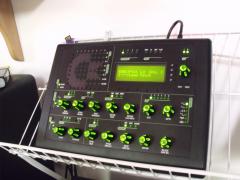
Building the MB-6582 Control Surface - Photo Tutorial
Hawkeye replied to Hawkeye's topic in Tips & Tricks
Conclusion (II) That´s it once again. Despite the CNCed plexiglass window screen, which I hope to obtain at some point in time, I cannot think of any other improvements to this fantastic synth. See image two for an overview of how a plexiglass window can be glued to the aluminum frontpanel from the backside. Thanks for the illustration, orange_hand! Enjoy & I hope you found the tutorial extension useful. Edit: Added a night studio shot with purple/white VFD filtering, which I like the most right now :-) Best regards, Peter

-
Building the MB-6582 Control Surface - Photo Tutorial
Hawkeye replied to Hawkeye's topic in Tips & Tricks
Step 22: Building a new protected linear PSU Notes: * Why upgrade from your old C64 PSU? Because it is old. And it contains an unprotected 20+ year old voltage regulator, that in a failure scenario will lead to a real mess - it will pump too high voltage through your MB6582, probably frying SIDs, your display and potentially the PICs. Not nice! * On the other hand... working with high voltage and PSUs is really dangerous! Be extremely sure, that you know what you do. If you are not, you can always buy (rather expensive) linear PSUs commercially. Or you can go for a cheaper "switching" PSU, which may (or may not, the discussion is endless) introduce audible noise to your signal path. The costs for this PSU were less than 50€ and it is really nice: - It contains a high-power 5V regulator (up to 2 Amps) and has more than enough power on the 9V rail (nearly 3 Amps). - It is fused to the max :-), with a total of four fuses in the PSU. - It also contains a "crowbar-protection circuit". In case of a catastrophic VR failure (aka over voltage), a thrysistor will short circuit the 5V rail and blow a fuse. - It contains LEDs for +5V and the active protection circuit. - It contains "long livable" capacitators - high temperature variants, that you would normally not get in "consumer hardware". - The case is nice and very sturdy. Description: * This build is nearly identical to the description from retro-donald.de: http://www.retro-don...wernetzteil.php * You can test the crowbar circuit (Picture 13) with a lab PSU - I did so. It triggers when 6.2V are reached (simulated catastrophic VR failure) and shorts the rail. Very nice :-). You could also create the crowbar circuit for the 5V rail as a standalone separate unit (with a fuse!) and reuse your old C64 PSU. * I will not cover the build details this time, because of two reasons... first, you really need to know what you are doing - and second, I won´t take any responsibility for damages (to you or your environment) by reproducing the PSU. So please accept this as a mere picture gallery - no build description and part list this time!


-
Looks fantastic! You could consider the new green Newhaven 4x20 OLED for additional pimping :-) Best regards, Peter
-
Building the MB-6582 Control Surface - Photo Tutorial
Hawkeye replied to Hawkeye's topic in Tips & Tricks
Step 21: Installing a studio-compliant 6.3mm stereo socket (passive mixer) Parts Used: * Göldo J002G 1/4 inch/6.3mm gold stereo socket (Thomann audio store, for example) * A length of wire and heat shrink tube * A 12mm drill, a countersinking cutter will do nicely ("Senkbohrer" in german) * A roll of electrical insulating tape * Your favourite soldering equipment Description: * First, extend the hole for the old 3.5mm socket to 12mm (photo 1 before modification and 2 after drilling). * Install the stereo socket * Solder wires to the passive mixer audio-out headers - no plug is necessary in my opinion - protect pins by putting on some heat shrink tube (photo 3). * Finally solder wires to the stereo socket, protect them with heat shrink tube and protect the whole socket with a layer of insulating tape (photo 4) for sanity reasons - the case closes nicely and neither the CS nor the display touches the new socket, so it is probably not necessary. Enjoy your better studio connectivity :-)


-
6.3mm Stereo Socket for MB6582 Passive Mixer Output
Hawkeye posted a gallery image in Members Gallery

From the album: Hawkeyes MB stuff
It fits perfectly... If you don´t have 8 mixer channels left, then this is the next best alternative to connect the MB6582 to your studio... The case closes without problems and there are no contacts to the CS PCB or the display. (-> See photo tutorial for more infos) -
 Thx, dude! Methinks, I know your emerald green one from facebook - very nice! It inspired me to do the red one :-) That brightness control is very cool - I have a spare LM317 + 10k pot, but for now am happy that the CS and the Frontpanel are back together :-) I´ve added your suggestion to the tutorial for other illumination crazies - thanks for reporting it! Bye, Peter
 -
Yakuza - our latest song using NES, OPL3, and the SID
Hawkeye replied to m00dawg's topic in Songs & Sounds
+1 likes :) well done! -
go Smithy, go! sorry for ot... still very interested in the patch :poke: :flowers:
-
Heheh, thanks Smithy! No fans - just passive cooling with special SID-sized heatsinks: - but you know that pic already. :-)
-
That sounds good :-) You won´t regret it!
-
Hi Antonio, the source code is here: But you need the exact same display... Noritake CU20045-UW5J VFD (Mouser 775-CU20045-UW5J) You can also get the compiled MB6582 .hex binaries from me, of course :-) Greetz! Peter
-
Thanks a lot for your responses :-) They made me very happy :-) It is only that bright, when its quite dark in the studio (long exposure here) - you don´t see the LEDs shining through the knobs - also I adjusted the resistors for the "normal LEDs" to match the brightness of the knobs (220R). The VFD on the other hand is really bright, which is nice because it can be filtered to nearly all colors and still retains enough photon emission to be stunning - it is a really recommended upgrade from a standard LCD :-).
-
Just follow the trace where your solder pad came off to the next pad. Solder one end of a short wire there and the other end to your corrected resistor, where the pad came off.
-
The sammich sure is a good starting point, you can control it via external MIDI controllers nicely. The MB6582 is good for higher polyphony in lead instruments. As a very interesting scalable alternative you can only build the MB6582 baseboard and add SIDs as you go can obtain them - and control everything via MIDI or the Rutgers Patch manager. Regarding the manual - the MBSID V2 manual is it - the MB6582 is "just" an awesome integrated/non-modular variant of it.
-
MB6582: ca 500-800€ depending on your component sourcing & customs duty avoiding abilities, component-type (encoders and display can make it cheaper or more expensive) and general pimping desires :-) Hours: you can do the baseboard in one night. The CS takes a little bit longer (I would guess ca 10-20 hours). Greets, Peter
-
From the album: Hawkeyes MB stuff
Using a color foil for VFD hue-shifting. Including a space invaders alien. Hope you like it. Outstanding work TK. & Wilba - Thanks once again! -
Building the MB-6582 Control Surface - Photo Tutorial
Hawkeye replied to Hawkeye's topic in Tips & Tricks
Step 20: Upgrading to an awesome VFD :-) (optional) Parts used: * Noritake CU20045-UW5J VFD (Mouser 775-CU20045-UW5J) * A dremel with a cutting wheel and a grinding/sanding tool * Your favourite soldering equipment Warnings: * The described steps are suitable only for exactly the abovementioned VFD. I searched for many hours trying to find a VFD that fits into the MB6582 with relative ease without big modifications. * The VFD also fits without altering the PCB with the dremel tool. But then you have to mount it a few millimeters deeper, and very slightly angled, which you may like or not - I wanted it to be as close as possible to the CS and be parallel to it. * The current consumption of the VFD is quite high. In conjunction with the increased current consumption of the backlight LEDs, I would therefore highly recommend building an alternative PSU than the 25+ years old C64 power bricks in use. I will therefore post a small mini-tutorial of how to build a more powerful linear PSU later on. Even if this is not CS-specific, I feel, that it is an essential upgrade - there are reports of fried SIDs because of catastrophic 7805 voltage regulator failure. Frying the SIDs and the VFD would be bad. Very bad. * Also, there may be a nice line of new 20x4 OLEDs suitable for your MB6582, if you want to avoid the high cost for a VFD. * But the SIDs are old-school. So a VFD it must be... here we go :-). * Unfortunately, this VFD does not run out-of-the box. Some driver adjustments were necessary - you can read on the process and download the driver in this thread: Description: * The VFD is wired exactly like the LCDs. Just "copy" the pins and you are fine. Note, that I´ve left out the data pins 1-4, as the MB6582 uses 4-bit mode by default and the wires are not necessary (photo 1). * As the VFD has some angluar pins just where the lower PCB display border is, you can take away ca 1-2 millimeters of the PCB with the dremel tool and a cutting wheel - there are no connections here, so no harm is done (photos 2 and 3). * Also, the VFD has a "coil" very close to one tactile switch. As only the upper section of the switch is used on the PCB, you can use the dremel with a ca 10mm "grinding tool" to take out that section (photos 4 and 5). Be careful to not harm the switch case though. Also make sure that the two shortened switch pins do not contact the exposed upper or lower copper layers of the PCB. * Insert the M2.5 screws to which you add a M2.5 nut from above into the four "display holes" on the CS PCB. Fasten these screws with M2.5 nuts from below the CS PCB. These also serve as a 1.5-2mm spacer between the VFD and the CS PCB backside. Now stack your display from below and fasten it with four more M2.5 screws. Perform a fitting test - no parts should touch when the screws are fastened - it is especially important to control the "coil" area (photo 6) and the region where you soldered the display connection pins. In case of doubt, use insulating tape to mask. * If you are really confident that all is right, connect all control surface connections and the display to the base PCB and turn it on. Make sure, that all LEDs, tactile switches and rotary encoders are working (photo 7). * Now assemble the CS PCB and the upper part of the PT-10. If you are using flat-head LEDs, take care that you do not apply force, otherwise they will bend. Check for any LEDs that will not 100% fit their holes, unassemble and bend them lightly in the appropriate direction. When it is done properly, at some point, the two parts will just "click" together. Fasten all screws and for sanity reasons use masking tape to "protect" the display pin area from unwanted contacts (photo 8). * When all is done, enjoy your new VFD (photo 9). I don´t yet own a plexiglass screen to protect it. Will keep you posted when I got it - frontplaten.net will produce them and they also have transparent colors available - which is great for shifting the color hue of VFDs towards the wanted color - or just limiting the brightness (by using a cool grey transparent window).


