Hawkeye
-
Posts
3,636 -
Joined
-
Last visited
-
Days Won
36
Content Type
Profiles
Forums
Blogs
Gallery
Everything posted by Hawkeye
-
To estimate the damage, we need hi-res pics from front and backside. You can most likely use a short wire from another solder point to fix the problem. If you need to desolder components again, first cut every pin at the top of the PCB, remove the component, then use a vacuum pump from the backside and your iron from the frontside for every pin to "clean" the holes.
-
Building the MB-6582 Control Surface - Photo Tutorial
Hawkeye replied to Hawkeye's topic in Tips & Tricks
Step 19: Create Knob Backlights (optional) Parts used: * 45 pcs SMD LEDs (1.5x3.0mm) (Red Water Clear Kingbright Standard SMD LED) (Mouser 604-APL3015SRCPRVF01) * a roll of enamelled copper wire (.35mm diameter) (e.g. Reichelt CUL 35) * a roll of standard electric insulating tape * your favourite soldering equipment * a soldering "helping hand" tool * SMD calipers Warnings: This is a time-intensive task. It is only required if you have non-opaque knobs (like the transparent waldorf knobs), that can be illuminated via backlights. Also, I highly recommend to not enjoy excess caffinated beverages, because, ehm... the LEDs are small :-). As I started, I needed over 20 minutes per "LED Loop", in the end around 10 minutes... and there are 15 of them... Otherwise, it is very meditative and great training for smd soldering, so... lets begin :-). First of all, I consulted a few people more firm in electronics than myself, and also read up on some tech resources... On each rotary encoder three LEDs should be mounted and wired in series for easier cabling... Normally, resistors in series to a LED are employed to limit the current that flows, because LEDs are not "linear" in current consumption... a very slight voltage increase leads to a dramatic increase in current... potentially over the limit and "burning" the LED. In this case, every LED only gets 1/3 of 5V, which leads to very moderate current consumption which I measured with a multimeter. Assuming the 5Vs are stable, nothing bad happens to these LEDs. This may vary when you employ different LEDs. Even if you use the same, always measure the current that flows, and verify that it is below the datasheet maximum. In many cases, 5V may not be enough to light three LEDs in series. You can then take +9V from the baseboard, but must then employ a resistor that matches your LEDs. In normal cases, please use a resistor and measure the current. I cannot take responsibility for burnt "direct-driven" LEDs. In fact, nILS takes all responsibilities :-). Description: * Use the enamelled copper wire, connect it to the +5V at the CS corner connector and wrap it around all encoder housings, like a telegraph line :-). Be aware that your wire stays clear of any holes in the CS - the standoffs must be free and not "collide" with your copper wire (photos 1 + 2). * Use one layer of insulating tape to cover the encoder shafts - you need to split it in half to have the correct height (photo 2). * Prepare a copper wire loop, by just wrapping a length of enamelled copper wire around an encoder shaft. Tin the loop at 120 degree intervals (photo 3). (You may need to have your soldering iron at a temperature higher than 400°C to melt the lacquer). * Cut the wire at your solder points - if nothing went wrong, e.g. one of these frequent reality bugs occured, you should have four shorter wires :-) - use a "helping hand" to solder the SMD LEDs and the wire pieces one by one, see photos 4-6. * Create a "standoff loop" that guarantees clearance from the encoder base (photo 7) * Connect the "LED Loops" as shown in photo 8 - one encoder pin is always grounded - make sure you choose the right one. Connect the other end of the loop to your "supply voltage line". * The LEDs should be really close to the encoder axis, otherwise they won´t "shine through" the relatively small holes in the frontpanel. You can bend the wire to force them into positions, where they are most effective - very close to the axis and quite at the bottom of the shaft. * When everything is ready your result could look like photos 9+10. Enjoy :-) Notes: * A SMD caliper is highly recommended for this task. Best investment ever for SMD tasks :-). * The SMD LEDs have markings for their negative pin, for example a color dot. Be sure to align all three LEDs in the ring in the same direction. * It is not necessary to use a special SMD soldering tip - I used my standard 1.6mm flat tip which worked great. * SMD LEDs burn quite quickly when you are careless with your soldering iron. Be sure to buy a few more than 45, because it is quite likely that you will lose some. * My friend jojjelito just informed me, that the SMD work can be avoided in two ways: a) use axial LEDs like these from digikey (lumex opto SSL-LXA228SGC) - they are a little bit more expensive but that will easily be compensated by the time saved. b) use a transparent washer and glue LEDs to the side of it - you will obtain a nice area light. Nice tricks, thanks! :-) * Also, Wilba just used normal "through-hole" LEDs, that were connected to GND and a supply line and then bent very close to the axis. * Lastly, Altitiude recommends using a LM317 + fixed resistor + trim potentiometer (look in the datasheet for a connection example) to be able to dim the backlight brightness. This is a very good idea, as it allows to adjust your LEDs to the optimum current draw.


-
not too much though or the knobs will slip on the encoder axis while turning :-) ah no, d-shaft to the rescue :-)
-
 Good it was your invention - i saw the marketing guys at osram led division go berzerk with names like "ultra red" and "hyper red", so "porno red" is not soo far off, we will likely see it in 2012 :)
 -
Try again to exchange the problematic sid with a working one to make 100% sure its not the sid. Otherwise, closeup hi-resolution pictures (frontside and backside of the pcb) of the output section (above your problematic sid) would be nice, so we can have a look :-)
-
and don´t use "photoshop -> adjust hue" - i would notice that heheheh
-
did they sell as "pornographic red"? lolz those marketing guys are insane :-) Nao waiting for a poidh of Emerald City!
-
From the album: Hawkeyes MB stuff
ah those lead free solder fumes dont make happy no more :rolleyes: (backlight smd leds for transparent mb6582 waldorf knobs - last "night shot" of them, i promise :-)) -
fm-licious :-)
-
Sounds nice! Def. usable in some dark tracks :-)
-
The power supply is right for for both options. To see which one has been chosen by the builder of the MB6582 baseboard, we´d need a hi-res picture of that. Please test the power supply for correct voltages (9V AC, 5V DC) before connecting it to your MIDIbox -> the old Commodore PSUs are not too reliable and can fry your MB6582: http://www.hardwarebook.info/C64_Power_Supply You may not have all the pins depicted in the above picture, that is perfectly ok (different revisions of the plug).
-
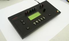
MIOS32 Voxel Space Graphics Demo on 256x64 Graphical OLED
Hawkeye replied to Hawkeye's topic in MIOS toy of the week
Had an optimization idea - the resolution is now quadrupled to the displays´ native 256x64 pixels (formerly 64x64 stretched) without noticable speed loss - also I recorded this a little bit closer and in HD, so you can see all pixels :-). The music is a takeout from a rainy afternoon synth jam :-) Also, the codez are now in the repository (mios_test/app_lcd/ssd1322). If anybody has got an idea for "smooth" live updating of the heightfield for different views -> plz contact me :-). Now, on to more serious things :-) Bye, Peter -
SammichFM - Control Surface Problems **FIXED**
Hawkeye replied to Electric Ungulate's topic in MIDIbox FM
Hi there, could you provide us with high-res photos of the PCBs (front (with chips in) and backsides), so we can have a look? Also, a description of what is not working (everything, only some switches/LEDs) would be great! Greets, Peter -
+1! Am very interested in your "Matt Gray" patch!
-
MIOS32 Voxel Space Graphics Demo on 256x64 Graphical OLED
Hawkeye replied to Hawkeye's topic in MIOS toy of the week
The VFD for the MB6582 works fine :-) - watch the photo tutorial, will update it soon :). -
MIOS32 Voxel Space Graphics Demo on 256x64 Graphical OLED
Hawkeye replied to Hawkeye's topic in MIOS toy of the week
Thanks :-) The display looks fantastic and fits perfectly in the MB6582 display area ("raiser veroboard" needed). It is my hope to convince TK., that this is the perfect upgrade path for MBSID V3, so all we MB6582 users don´t need to build a new frontpanel (which is expensive) and my "Construction Phototutorial" does not get obsolete before MBSID V4 :-). I´ve just managed to get better timings, there is very slight flicker going on now, which is only visible when there are big bright areas displayed (e.g. "full on" display). Bye, Peter -
Yes, the problem with the SSD1322 datasheet is, that it refers to the same controller, but contains the settings for an arbitrary non-Newhaven display (e.g. a display @ 480x128). The Newhaven datasheet itself does not say a word on which addressing mode is used (there are a few possibilities) and the particularly necessary values for phase length, clock divider/oscillator frequency, pre-charge period and pre-charge voltages, as well as contrast settings. These values all depend upon each other like for an old fixed frequency monitor. Using extreme values for this, some nice FX are possible and the OLED really looks a lot like an old electron tube display :-). Methinks, I will address the guys @ Newhaven in their forum and ask them for the correct settings :). Edit: just did that, the thread is here. Best regards, Peter
-
This topic contains the promised animated demo :-) - gosh it was fun, i want teh old timez back :)
-
It was just for fun. If you are interested in teh codez, you can have them :) Best regards, Peter
-
haz made a small Voxel Space Demo on 256x64 OLED using new LPCNespresso Core :)
-
Update... i have a good feeling regarding the ultra-nice and cheap 256x64 OLEDs from Newhaven :-) Will present an animated demo, when I found some time to convert some old code :-) Thanks to TK. - without him = no chance to get this running.
-
Smithy-express.com only 999USD. Or DIY :-)
-
 Arti, while I understand your wish to preserve things, he has "just" converted an empty case - which would have rotten on some basement anywhere in the world - converting it to a much loved and often-used midibox is a great thing to do, so others can see how fine the zx spectrum 128k was (i did not know it before!). Also, this conversion was done with a lot of dexterity and good handicraft knowledge and I think it looks marvelous :-) Bye, Peter
 -
Yo, the Newhaven character OLEDs are mighty fine and are compatible (converted a waldorf micro q a few days ago - picture here: http://img535.images...8536/mg9636.jpg) Yesterday, TK. and me were tinkering on the 256x64 graphical "Tempest" OLED from Newhaven (SSD1322 driver in the repository) - while the display itself is very impressive, we were yet unable to get usable output due to not-understanding how some things work and some flaws in the datasheets. Bought via Mouser or Digikey. Bye, Peter
-
Don´t grease, use Smithies powerful knob removal tool. Hot!