

technobreath
-
Posts
877 -
Joined
-
Last visited
Content Type
Profiles
Forums
Blogs
Gallery
Everything posted by technobreath
-
Shithe, I can't figure out how to edit post using my phone.. I mentioned earlier that iirc u get vregs up to 2a max. Those are the 78sXX vregs. Of course there is higher rated vregs around, but what I meant is that u get up to 2A in a TO220 package. Higher rated vregs seems to be mostly in those metal can packages, and those are not that practical when it comes to heat sinks... Sorry for the double postings here, but I really found no edit function in the forum on my phone...
-
Hey. I had a look at that psu now. It looks good on schem, but as I said before in the post, the input ripple filtering caps need to be the right values for current draw and input voltage, else ripple will not be filtered as good as can be. I haven't read the instructions on this in detail, but if it doesn't tell u to watch out for the input caps value to be high enough, and the ceramic ones to be close enough, it serves as a brilliant example of one of those confusing design instructions I talked about. The case with the ceramic caps are all in the vreg datasheet also. It took me a long time to understand what happens in a linear psu, so I don't bug those who hasent read a lot bout it and gone through that learning curve I did. That is why I say, do not trust designs all together, read some sheets and see why it is the way it is, and if there are special considerations to be taken into account when doing PCB layout. Just a tip hehe. So as you found out P, what u did was actually to correct some design errors that made this psu operate outside specs, and it worked for u then. Veery nice. Good job figuring it out. It is cool when people combine knowledge to address issues like this. I may be a atypical man with this, but I almost always read the datasheets to better understand the building process, and when I'm too lazy to do that I ask nils hehe, and he always bites me back and do a let-me-google-that-die-you to me hehe. Well, not completely true, as he have helped me a lot getting started on my psu quest, and during the quest smashtv has also been tremendously helpful! I made part of the PCB layout today for the psu, but since eagle free is so nice to not let me have those big pcbs in there ill have to make the crowbars on another module hehe. Let me also add that the psu u link to here peter, is slightly different to my approach. My goal is to take every psu component out of the mb6582, so I output no 9v ac. I have 5, 9 and 12v dc outputs. Mainly because I have all the psu components in one box then and not some in the synth and some in the psu box hehe. Makes service easier and also makes heat in the synth less of an issue, because u move all vregs out of there. Now off to tetris some crowbar module. Hehe. Have fun.
-
Hey, I am scratching my head here too. There are all kinds of more or less exotic variants of linear psu designs out there. Both here and online. First of all one has to find out how much current u need to have available to the synth, and in my opinion, the brick is in the lower end of this, and without any proof I will say it either way. It may be exactly why it dies on some people. Stressing old components like that to its limits is in my opinion to ask for trouble, and if it hadn't worked for most users I would scrap the idea. Now this is only my humble theories hehe. As for designing a modern linear psu - linear is recommended for this unless u have a scope and know what u do when designing a switcher - it is fairly simple to make a linear that works well. Only thing is that u gotta know how much current u need, read some datasheets for the vregs and you should be quite some way to the psu. The vregs have specified max input voltages, max current rating. This is all based on the assumption of best case scenario with almost always 25c as the ambient temperature. Of course these ideal assumptions aren't the case in real life. So u need to use some brains here to figure out realistic operating criterias. Ones that is done I don't see any problems using the components within specs. There are tricks to do things a bit easier temp wise. Put the heatsinks out of the enclosure. Make it big enough. U don't need the psu to be as small as possible. Easy trick, right? What u basically need to construct a linear psu is transformers, input smoothing caps - those are the big electrolits u see in most schems around. These can be used to filter input of many vregs, u don't need to have one / several for each vreg. U need vregs of course, and u get iirc up to 2a max output current (keep in mind this is not realistic, but ideal conditions) The vregs also need one cap at the input and one at the output. These are needed for each vreg, and in datasheet u find how close they physically need to be to the vreg. Often an inch or so. Of course this is the electrical path, u can't stick the cap right next to the vreg and then route the path around the board and then expect it to be ok. These caps are there to keep the vregs from oscillation aka make funky electrical hi freq noise on the line. The size of them is clearly stated in the datasheet also, just follow that and don't think too much why and how on those. Then a 2nd smoothing cap is used at the output of the vreg too, a lot smaller than the input caps. Helps stabilize the line more if there is some noise left after passing through vreg. The input caps need to be big enough for the current drawn from the psu. To say it simple. The higher voltage u fees the vreg, the smaller caps u need, but also heat dissipated from vreg increase if it has to burn off more voltage. So this is a game to find the golden way between two scenarios. There is formulaes to get this right, I can't remember them right now. I usually use a simulator sw to load test the circuit, and when watching the scope I can get some clue to how big caps I need. But if u like math instead, we have Google. These days I have been picking up on designing my psu for the mb6582. It contains no funky resistors etc, and is completely within specs and design rules given in the datasheet of the vregs. So to make this short, u don't need any funky stuff when using these vregs. U can manage without resiators to lower stress on the vregs etc, resistors also add noise to the line. I can't with my best available fantasy thoughts understand why one would want to go all funky about this when the specs are so easy to follow. Just keep the heat away from the vregs with a big heatsink... They are made to burn off heat, no need to cuddle them! If they get too hot there are also thermal shutdown thing in them mostly. I can't promise anything to when my design is gonna be ready and tested, but when I have made it and test it ill make the design available in the wiki pages. I'll also post pics if scope under stress testing, and also pics of temperature on various places in the psu and ambient temp. Info on proper heatsinking etc. Please do not interpret this as me coming here thinking I'm much better than the rest, but I believe I have some good points, and as I said in the beginning, there as are many funky out of specs designs everywhere, and it only serves two things - to confuse the builder and give the builder a crappy psu. Might work, might not work, but in the end, the smartest and easiest thing is to just follow the datasheets and trust that the ones made the component really knows what they are doing. /signing off.
-
Hehe, painted black those leds would look like darth vader's helmet. How is the light emission? What kinda paint is that? Is this done to make a silver tint on the leds?
-
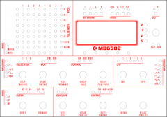
From the album: technobreath - All synth related
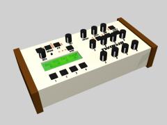
Well, here's my version of Wilba's great layout. In the files available from him, the graphics were all made by lines and curves and what seems to me to be adapted to some kind of engraving process.<br /><br />With some tips from Wilba, this design is a complete redo of the graphics. Holes are the original ones, but this file contains normal text wich one can change size and font type for without much effort. This also makes it perfect for silkscreening or printing.<br /><br />Based on what I know about silkscreening, you will not be able to do the blured outline around the LCD with silkscreening. The rest of the graphics is totally doable. However, I'm not personally using silkscreen, but a printing process that in short is printed graphics on the back of acrylic panel.<br /><br />I've sent this layout over to the printshop I use, and will get an estimated price for a completed panel.<br /><br />I realized a couple of days ago that it is the CS panel that were keeping me from completing the synth, as soon as I have made a suitable powersupply that is, so now that it's autumn here, I found it about time to do something about this :).<br /><br />So this is the result.<br /><br />Any comments is welcome.© technobreath
-
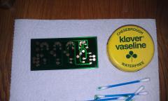 yo nebs, thanks :) The brand name of the solder mask is Bungard GreenCoat. Here's a linky to the datasheet: http://www.krepro.no/index.php?dispatch=attachments.getfile&attachment_id=271 Was a bit spendy, and u wash it off with alcohol or acetone, so cleaning with that afterwards is a no no. But for small boards it works well. However, I really recommend u mask up the pads somehow - for example with petroleum based vaseline like I did. Then u can just wash it off with soap and water afterwards. Soldering iron and nose / brain doesn't like to solder through this even though it's very possible. Imho this solder mask is more a cosmetic mask than a real solder mask, and I'll probably not buy another can when it is empty. By that time I'm probably ordering the prototypes. But for a great look at a simple homemade board, it is super, as long as u know of it's limitations :).
 -
got a Weller WTCP51 in his lap right now. Cuddles it :D
-
From the album: technobreath - All synth related
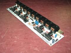
PSU board together with the good stuff.<br /><br />When I had etched the board I cut the tip of a q-tip diagonally, so it was sharp and pointy. Then I use it to apply the vaseline to all the pads. A rather blacksmith kinda way to do things, but certainly worked well as you can see. It took great care with the q-tip to not spill vaseline all over the place.<br /><br />When the pads were masked with vaseline, I carefully sprayed the soldermask on. Let it dry, then let it dry even more under my wife's hairdryer - then I carefully tried to remove the vaseline to see if I could remove it without harming the soldermask (I wasn't quite sure it was all set yet). But it was, and I just used the q-tips to remove the vaseline, and then washed it with soap and water to remove the rest of that good stuff.<br /><br />The results you see here. A little unprecise with the masking of the pads (too much spill) but I am really pleasd with the results.<br /><br />The soldermask is one of those "solderthrough" spray-on soldermasks, but smash told me it was much work cleaning the iron during soldering through the mask, so... that is why I did it like this. No tip cleaning / tip-ruining :).<br /><br />Now it only lacks holes. Smallest drillbit I god is 1mm. Too big for the smaller components, and it can be difficult to fill all the smaller pads, and not just half the hole, because it is too big, but with a bit of practice and care it goes just fine. 1mm is about the smallest drillbit the chuck on my drill will accept too, so I gotta make it work ;).© Technobreath
-
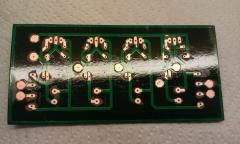
From the album: technobreath - All synth related
OK. Second of these board I etched. The first one was kinda dirty, soldermask didn't look good etc - in short - it worked very good, but I didn't like it :P...<br /><br />The other picture will explain how I did the soldermask.© Technobreath
-
 One board scrapped, new one made. I wasn't quite satisfied with the way the soldermask turned out. :). Pics to follow.
 -
 nice. It's always good to see another 5x5x5 born! Let those greedy manufacturers of the midi modules know that we can do it cheaper and better! :D
 -
Thanks. /me knows :). Thanks for watching out for me though :). I use clips to attach the cases to the heatsink, and also isolation rubber. I just started soldering the board today with the components I got laying around, the bridges, the small caps, and the vregs 9 and 5v. The rest is probably delivered today, but it's too late to do something now. Oh, I tried a solder through spray on mask - lets see how that works out.. :).
-
did the first two toner transfers ever for the psu. It turned out it is mirrored... :) lol. I was so obsessed on mirroring the design onto the board that I made the printout mirrored, so it got non-mirrored when I transfered it :D haha. stupid.
-
- Massive amounts of thanks goes to SmashTV & Co for all the nice tips on psu design. Not that I claim it's good enough for them to put their name on it hehe, but they have been nice enough to look at my crazy ideas :) Thanks :)
-
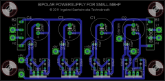
From the album: technobreath - All synth related
Well. Another PCB design of the PSU for the StereoSID. I thought I was done with the last one, but critic voices told otherwise :). So Here it is, hopefully the final version. More compact, looks tidier, negative vreg on the far right instead of in the middle. etc etc. Please tell me what u think of it :).© Technobreath
-
Got a new washingmachine. MMMMM Brushless motor. Even on full speed I gotta stop by the bathroom to see if it still runs - I can leave the ear protectors in my car now...!
-

Audio out preference (RCA, 1/4", Mono, Stereo)?
technobreath replied to m00dawg's topic in Design Concepts
A standard PSU will sure fit in free eagle :). But I don't know about the one I have in mind. It contains a lot of ICs (vregs, vrefs, comparators etc) and also relays. So it will be fun to see how it works out. -
Audio out preference (RCA, 1/4", Mono, Stereo)?
technobreath replied to m00dawg's topic in Design Concepts
I might have to check the right places for the chemicals... I might look into it when I have used up my 2kg of FeCl hehe. As for psu, the only reason I have bipolar rails in there is for the opamps at the output board, and of course for the headphones amp. I'm not doing any other bipolar stuff with the stereosid, so that's why I'm doing it 15v. For the mb6582 psu I will not include any bipolar rails either. Oof that psu scares me a bit. It's gonna be some work routing the PCB, especially within the limits of free eagle... I have made several circuit designs, but its some time ago, and I already see I forgot the details of the operation hehe, gotta do some sim work to fresh my mind up a bit, then I will transfer it to eagle for the PCB layout making. I will have to go back on one of my main demands for the design, to be able to pump out 5amps of the 5v rail. I do not longer need that since the mb6582 is the only load, I planned on using it as a central psu for other controllers, but now I have simple PCB for psus, so if u need another one ill just etch it and solder it together, no big deal... So I am gonna try to see if 1,5 to 2A is enough... I get away with TO-220 cases then. And a slice of my heatsinks too hehe. No bipolar rails also means less concern of isolating the vregs on the heatsink too. I am scared of beginning on the designing of it, but on the other hand a part of me just can't wait, so I think I'm just gonna start on it, and we ll see how it goes hehe. -
Question about a part that might not exist!
technobreath replied to Kvetch's topic in Parts Questions
What are u connecting together? Agreeing with lylehaze. Keep grounds together. Might be able to use a 4pole rocker switch then. But its kinda unclear if u need 5 or 6 poles. Another alternative if u have a bit of space available is to set up a relay solution, then u only need one pole switch... You can use a relay that has NO/NC. And set up the number of relays u need. If the relay is energized, it sends the bus to the NO terminals and if not it goes to the NC terminal. I use this solution at work all the time to switch multiple poles with one logic output from a PLC. One specific relay board comes to mind. Noby JS1. It has two sets of NO and NC connections each. U can use three of them and a switch, then you have a 6 pole rocker switch. I only have docu on it Norwegian, so no link. If you are unavailable to get that or other relays, I am able to supply them cheap occasionally. Their control voltage is 10-30vdc. Can each relay can candle 47w, quite a bit, but they are small. I would say about 2x6 cm or so. If I were to build a electro mechanical solutions those are the ones i would use. But most likely I would do a transitor switch kinda design, but that requires some knowlegde about design. Relays and switches is very easy to understand, even for a beginner. -
Yo Guru. I haven't looked closely at it, but isn't that what the TwinSID is - there's a lot of pics in the gallery right now... Maybe stupid to mention as u no doubt have seen those pics ;)... Modular is nice! Easy to replace boards too if something goes wrong :).
-
Hi. 140-HTRL25V47-RC 140-RGA470M1EBK0511P -> 140-RGA470M1EBK0511P = Direct replacement - exactly the same specs. Use with confidence. 140-HTRL16V100-RC 140-RGA101M1CBK0611P -> 140-RGA101M1CBK0611P = Direct replacement too. 140-HTRL16V2200-RC 140-RGA222M1CBK1325P - > 140-RGA222M1CBK1325P = :o Direct replacement too. So, all of the alternatives have exactly the same specs as the list you wrote with the ones that is out of production. A word on capacitors. These are incredibly easy to compare. What you are looking for in the specs that are important for these diy projects here (not going into too much technical stuff) is: 1: Capacitance - the value of the cap - for example - 2200uF, 47uF etc... 2: Voltage rating - make sure the voltage rating is within specs. That is - if you are using the caps for a powersupply component wich is usually the case with 2200uF caps on midibox projects - if you feed the circuit with say, 12VAC, from the secondary side of the transformer into the rectifier, the cap should have at least 16V rating. You can't use lower rating than the specs say, but of course you can use higher voltage rating without problems electric-wise - BUT a 2200uF capacitor with 16v rating is physically smaller than a 2200uF 25v rated. That may be a problem when it comes to fitting it on a ready made pcb ;). But the dimensions are all there in the specs or datasheet, so no problem to find out if it matches your needs or not, but if you not know what to look for, it is best to keep to the original rating when substituting them with other alternatives. 3: And the dimensions. Should be the same. Of course you can always bend and twist leads around to make it fit etc... but it aint optimal hehe. Also when it comes to dimensions you have the layout of the component. caps like these you link to here (electrolytic caps - wich are polarized!) you get in both Axial and Radial. Axials have one lead out each end, and mounts with the cap laying on the board horizontally. Radial has both leads out one end, and mounts vertical on the board - or you can of course lay it down horizontally too... you know the drill. As I have no idea what kinda background you have, I tried to explain the important stuff when choosing subsitute caps - so this may be too much "babytalk" for you :) hehe. in that case - bare with me :). It looked like you had problems deciding on what specs to look for, so now you should know how to do it ;). Hope it helped, T EDIT: and oh - WELCOME! :D
-
 Also, what software did u do the drawing in? I have some 3D cad program, wich is very limited in when it comes to textures, and I have been using 3dsmax, but it is so heavy to work with...
 -
OK! Nice! Can I ask you what controls you have on there? For my stereoSID I'm doing some extra controls - a minimum control surface with some extras, but I have yet to decide wich controls to use... :)
-
Audio out preference (RCA, 1/4", Mono, Stereo)?
technobreath replied to m00dawg's topic in Design Concepts
Good tip... I have looked at hydrogen peroxide stuff before, but for a completely other issue. It is really hard to get the right consentration ratio in small quantum here. And u have eBay, but the customs are so much hassle with importing liquids like that. So I think I will stick to the FeCl since I know how to use it, and it is way easier to get here. The designs are posted as pics in the gallery. I know u already found em, but anyway if others didn't know... Hehe -
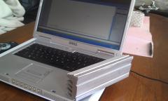 I have about 2 meters of this kinda heatsink ready to cut to me needs :P. Should be sufficient for cooling some tiny vregs, no? :P hehe.

