Search the Community
Showing results for 'STM32F4'.
-
FWIW I use MBCV2 regularly on an STM32F4 core and an AOUT using MAX525s, and I have some DOUTs doing gates. It works great in my DIY modular synth. Everything you described in your post sounds like it is doable in my experience. Whether you even need the second core running NG is debatable, that'll depend on how you want to connect to the Behinger (which I'm not familiar with, so can't comment). I wouldn't say it's a dead project myself, super usable and the interfacing with Lemur is amazing. Good luck with your project!
-
So as I see, there is a microcontroller core - old PIC based and new LPC and STM32 discovery based. Is it really comfortable to use discovery boards? Haven't you thought about nice PCB with place for MCU (as STM32F103 one)? I wonder if any part of discovery board is used except the microcontroller - thing is STM32F4 cost locally about $35 and the chip itself is about $12. If the schematic for STM32F4 core board is tested, I can make the tracing for separate MCU and share it. Same thing is for in/out, analog, midi and other modules you connect to main board - haven't you thought to use SMD components, place them at both layers and make PCBs really small to fit into a portable device? (because I'm seeking for it at least) - like AKAI APC KEY 25. So if such thing is interesting - I can do that.
-

(WTB) Seq V4 parts ( 2 raystar oleds for trade )
mantaray replied to Macotronic's topic in Fleamarket
I may have many of the parts you need. I just can't see me ever getting this built - every potential avenue towards finding a builder seems to meet a dead end. I think I have Wilba front panel PCB, parts kit, STM32F4 core, plus some MIDI boards. I will have to check what I've got, it may take a few days for me to look through the cupboard and find/check everything! -
I have a PCB for Wilba's Seq v4 frontpanel, new, nothing soldered to it yet. I have other parts as well that I could probably part with... I have a set of the rotary encoders and a set of the bicolor LEDs... A datawheel knob... I have an assembled LPC17 core that I could get rid of as well - it's a totally functional core for the time being, although as the SEQ forks off into the V4+ you'll miss out on some functionality down the road. You can always upgrade the core though. I could put together a set of knobs that would fit the encoders, but they're potentiometer knobs, so they've got that position indicator stripe on them, and I might have to mix up colors a bit, not sure if I have 16 of any one color... Anyway, not the prettiest knobs on the block, but they would work. I have an assembled STM32F4 core as well that isn't being used right now, but I think I want to keep it. What color are the OLEDs? Where are you located? Anyway, let me know if you're interested in any of that.
-
Hi Im on the hunt to get the part and make it I need -Switches -Potentiometers - MIDIbox Core STM32F4 and pcb -Parts kit I have two Raystar Oleds for the Seqv4 for trade
-
Hi, I'm unable to get both keyboard transpose and recording working at the same time. I can make only one or the other work, they won't work with the same settings. I'm using the Mk.ii panel, and have tried this with both LPC1769 and STM32F4 cores with firmware version 092pre1 (the newest available on the MIOS32 download page is 086, the newer one was probably available in some forum post in the V4L thread). What I'm trying to do: record some phrase using step (or live) recording stop recording and use the keyboard to transpose the phrase But I haven't managed to get these working like this. It would make sense it would work like this (first record something, then use the keyboard to transpose it every now and then and jam away over it using another keyboard), but I guess the first question is, is this really the case? Is this how it's supposed to work? What I've managed to do is: either record some sequence, which then plays back. I can play over the sequence if I want, but the sequence will be the same, no keyboard transpose is possible (whether or not Transpose is active or not); or, on the Trigger page, turn on some triggers and hear the C-4 notes play the synth. You can transpose the C-4 based rhythm to the key you play on the keyboard, but you cannot record your own sequences that you could then transpose. The Mk.ii panel wiki page says, If the setting is 0x00, I can transpose with the keyboard but not record (or forward notes played on the keyboard even if I->O is on), and if the setting is 0x01, I can record with the keyboard (and notes get forwarded when I->O is on) but not transpose (even if Transpose is on). Apart from this setting, I have not edited other parameters in any other files. What am I not getting?
-

dipCoreF4 and dipBoardF4, a compact Core.
Antichambre replied to Antichambre's topic in Design Concepts
Have a look on J18 here: http://www.ucapps.de/mbhp/mbhp_core_stm32f4.pdf Interconnection is like this for MBNet: http://www.ucapps.de/midibox_sid/mbsid_v2_communication.pdf Last diagram is for PIC but it's the same. J18 is present on all Cores, Disco, wCore, you can already try it if use STM32F4 for your project, just 'one wire' ;) ... 2 wires(signal + ground). -
Hi Roel, congrats to the build, thanks for the confirmation that it mostly worked out without a problem and glad that you like the docu, can't wait to get working on the second part! :). If there is similar feedback from other builders regarding the cheaper 6N138 sockets, we will replace them in the BOM. Personally, I've not yet had problems with them, but you are right, you need to make very sure, that the IC legs are properly bent for them to fit nicely. Regarding the SD-card, can you try to format externally using your computer using FAT32 as a filesystem? If the micromatch connection is ok, you should then be able to use it in the SEQ. (You could use the MIOS studio filebrowser to verify it works and try to store files on the formatted card via MIOS Studio filebrowser). You can also partially test some of the PCBs that you built using MIOS studio, e.g. if you enter "play" (or "start", can't remember right now :)) at the console prompt, a backside LED should flash (like in the video right at the beginning when the unit backside is shown), the other backside status LEDs are yet unused - the v4+ software would need to be extended a bit to make proper use of them (should not be terribly difficult, i think we could indicate "BLM connected", "Gate" and "MIDI in" activity with the remaining three LEDs). Also, when the sequencer is playing, the first track imho is filled with some notes per default, so if you attach a synthesizer to OUT1, you should be able to confirm that the first port on your MIDI8 PCB works properly. There is no ethernet extension planned (or room for it in the case) - effectively "on board ethernet" was dropped after the LPC17 core generation and the introduction of the new STM32F4 cores. But i am sure, if there was enough demand, with a bit of tinkering, it should be possible to design an "out-of-the-box" solution, that might connect e.g. to the BLM port (also carrying power) or two classic MIDI ports (external power required then), which could provide ethernet forwarding. Until a solution like that is implemented, it should be possible to forward/route a MIDI pair to your old sequencer and use that as an ethernet bridge (even if it does nothing else and just sits in the corner :)). Have a great day and many greets, Peter
-
@ilmenator no worries, we are planning on releasing the schematics, we are the good guys! :) Also be assured, that In this case "priority" really is that, we have to still validate the new UI boards, adjust configuration for left hand / right hand jog models, create the second/final soldering/build video tutorial, slightly modifiy the firmware for the new activity matrices, and have a dozen other little tidbits on our todo lists. It is just a lot of work, and the release of the schems is not being on the top of the list. As we have normal day jobs and families, these are all time-consuming "after-work" or night activities, deeply cutting into the hours normally allocated for sleep, atm :). @eptheca yes, technically you are automatically running a "v4+" with any stm32f4. It is caused by a code preprocessor "define" looking for the processor variant. This is for simplicity, so that only a single firmware .hex is needed for any stm32f4. Nevertheless, you won't be able to use the new v4+ UI features until you enable the "antilog panel" hwcfg section to benefit from its features. We have no problem whatsoever to call the v4+ officially "midiphy SEQ v4+", if it helps to differentiate things. For me, the only important point is that "v4+" is in the name, because that defines the hardware capabilities of the unit, that the software can rely on. Best regards, Peter
-
It seems that my suggestion for a clarification about the name was not that stupid, because you all explain the SEQ V4+ a little different. How can the V4+ be the new UI/frontpanel when I am already running it with a Wilba frontpanel? The way I see it, V4+ is the firmware version that only runs on a STM32F4 core. It can be used with a Wilba frontpanel and a latigid on frontpanel just with a different HW file. Some new functions will work on both frontpanels, like it already does with CC layers for drum tracks, and some new functions will probably only work or work best with the latigid frontpanel. Therefor it makes sense to me to be clear about the name. From the changelog: MIDIbox SEQ V4+ is a special firmware variant for the STM32F4 core.
-
Hi Hal, thanks for asking :) Regarding the questions, Bruno already answered the part, that midiphy is the name of the shop. As we should also have another MIDIbox based sequencer called LoopA as an "essential kit" in the shop hopefully soon, it would therefore be best to keep the name of "MIDIbox SEQ v4+" or "midiphy Seq v4+" or whatever you can think of, as long as it contains the v4+. :). That "plus" stands primarily for a general user interface improvement, designed by TK. and Andy over the last two years or so (see old thread). But the "midiphy Seq v4+" additionally also brings a new case solution, with the case being designed by Hallik Engineering, especially for this hardware, so all fits nicely in the box and will not take away too much room. The v4+ also has really great mechanical-keyboard-style switches, nice OLEDs, two mini LED matrices and lotsa bling :). Also, it should be easy to source/order, with only two orders in total required. As stated before, we do all of this, as we want to push MIDIbox and not enrich ourselves, we try to keep the prices moderate. Midiphy as a shop will also be trying to "host" other interesting MIDIbox user projects as well later on, so that interested users can get easier access to other awesome developments. To answer your other questions: * yes, you can reuse all your old v4 PCBs (as long as they are STM32F4 based) to drive the new UI, but they probably would not fit in to Adrian's case (Hallik Engineering). * yes, you should be able to reuse the TPD and BLM 16x4, if you attach it via the Line Driver expansion board, build a Line Receiver module and attach the BLM/TPD to the SRIO of the LINE-RX PCB. If you build your own (bigger) case, the line drivers might not be required. * Adrian has designed the v4+ case and spent lots of hours and quite a few (costly) iterations and he has the last word, what should be be public. Personally, I would vote for a publicly available "cutouts DXF", that contains the required holes in the frontpanel, so that users with other core PCBs or another intended case can create their own case while being sure to be able to mount the OLEDs, the two LeMEC boards, the new JA board and the mini matrix properly. But Adrian has the last saying in this. In the end, exactly as Bruno suggested, the v4+ is "just" a major user interface improvement! Some features of the v4+ will be instantly available on your old v4, but of course the expection are the hardware-centric improvements like the new selection model and the mini matrices. It is likely, that "v4+" designation in the config file defines an "expected set of well-known hardware capabilities", that can then be used by the sequencer app. So, while i expect the firmware itself to stay identical at least for a while, defining "v4+" in the configuration will (for example) switch to the new selection model and require the new UI hardware. Many greets, Peter
-
This is really great work guys. I am always impressed by all the talent, knowledge and creativity in this community. Could I suggest that we call this just the Midiphy, so we can differentiate between the Wilba and the Midiphy MB SEQ V4+ If I understand correctly the Midiphy is a new frontpanel. The MB SEQ V4+ relates to the STM32F4 Core and can be used with the Wilba frontpanel, at least that is what I am doing now. This is no criticism, I am just pointing out a possible area for misunderstanding in the future. My buttons are staring to fail as well, and playing live this weekend it was a bit annoying. I have a few questions: - Can I have my @ilmenator TPD and BLM 16x4 connected to my V4+ with the Midiphy frontpanel? - Can I use my STM32F4 Core, 2x MIDI I/O, 2xQuad IIC and AOUT_NG with the Midiphy frontpanel? - Will there be a DWG/DXF/FPD cad file available to design and order custom frontpanels? Cheers, Hal
-
 Thanks all for the replies! I solved it in the end by hooking the RESET pin of the OLED to a GPIO pin of the STM32F4 (J10A pin 7 on the midibox board) and a pull-up resistor, and then pulling the pin low in code for 1s at boot, to ensure the OLED module is reset properly. I couldn't get any combination of capacitors and resistors to work. I noticed that I have quite a lot of noise on my 3V rail, caused by some WS2812 LEDs I have - even though they are running off a different 5V supply, I guess there is an issue with the common ground. Don't know if this was related. Everything else runs fine... For future reference, I am using these extremely common (and cheap!) 0.96" 128x64 OLED displays, from ebay, such as this: https://www.ebay.co.uk/i/302104546088?chn=ps&var=600918131598
 -
Hello, This is about a new STM32F4 mbhp, a very compact one. This concept is an answer to these three topics: I tried to draw the most compact core and mbhp board. It's an STM32F405RG instead of the regular 407VG. The 405RG is the smallest package of the M4 Series, this is a LQFP64, a 10x10mm package with only 64 pins. Because these two Processor are from the same family, we don't need deep changes in MIOS32. They have exactly the same functions, memory, speed and peripherals. I put the STM32F4 on a DIP-40 format pcb, in order to get a core that can also replace a PIC in some application, I strongly think of my sammichSid. At the same time it must provide the legacy functions and ports of MIOS32 of course. Some compromise have been made in comparison to a 407VG mbhp. - Only 2 MIDI I/O. - J15, the LCD port is now a serial one only(SSD13xx). - No more general purpose port J10x. This is the list of the 'remaining' ports and changes. - J1A and J1B are the USB and Power ports, J1A is compatible with latigid on's USB wCore module. J1B can be a common header on top or a Micro-Match connector on bottom to stack another board under. - J4 is a dual I2C connector, I put both on the same connector to save space. - J5 is a 2 channels only ADC, they can be used for expression pedal input for example. - J8/9 and J19 stay the Legacy 5V SPI ports, the dipCoreF4 includes the octal buffer(74HCT541); - J11 is now a 6pin and 2 MIDI I/O port. - J16E is the 3.3V SPI port, commonly dedicated to the SD Card it is compatible with latigid on's RES-SD modules. it is extended by the Reset input, the user button and 2 outputs for LEDs. - J18 has changed, it is now able to connect a CAN tranceiver, but stay compatible with the MBNET connection. About the dimension, the ensemble is very compact 65x46mm, but the Core can be used alone and measures 51x17.8mm. A 3D view of the ensemble(sorry this is not a render, I shoot the screen): You will find some more information on the dokuwiki, dipCoreF4 and dipBoardF4 Feel free to ask me question or give me any constructive criticism. I will order some board very soon, if some want to participate in the tests they are welcome, just contact me. I will provide the beta boards for free I just ask you to play the game and seriously help me to improve it ;) Thank you Best regards Bruno PS: sorry for my English as usual ;)
-
Ok, no problem, can write down my thoughts of the v4+ vs the v4, trying to be as neutral as possible. But first of all, thanks so much for the facebook ads, Bruno! :) We got a few new youtube subscribers within the last hours, so I was wondering what was going on, hehe! ;-) Regarding the v4+, by coincidence, i have given it an extended test-drive last night, just the v4+ and a Kawai K3M (that happened to somehow come to a rest on my doorstep lately, i really don't know how it happened!!! :). Gladly, the better half did not take note of it yet, otherwise the Nudelholz would have been swung at my poor head again! :)). Differences of v4+ to the v4. Really, this is not meant to be a sales text - we fortunately don't depend on selling the kits (as we have other jobs) and also hope to be able to provide fair prices, long term. We do it, because we love these things! Key differences v4/v4+, personal viewpoint: * The Matias switches with proper large-scale keycaps themselves. In my opinion, they are just so much better than the previous generation of switches/caps used in the classic v4s. If you like mechanical keyboards, it is a dream! In computer nerd talk, to me it feels like an upgrade from HDDs to SSDs :) * The second row of matias switches and the new "v4+" selection row mode, that can be chosen using the right-hand mode selection "wheel". Imho, it adds a whole level of interactivity while eliminating a lot of page-switches. E.g., last night, i spent probably an hour in the "transpose page" (that is controlled with the primary "GP" row of Matias switches and the encoders). Using the new selection mode wheel, i also at the same time ended up in "Selection: Mute mode", that is then assigned to the secondary row of Matias switches. Now, on a single SEQ page you can mute/unmute single tracks, while also transposing whole groups of selected tracks - that was really a lot of fun :). On the v4, this would of course work, too, but would require menu page switches for every new mute/unmute or transposition change, here you can just stay on a single screen and use the 32 matias switches for both functions at once. As the mode wheel acts as a mix-in feature, you can effectively control two things on a single page and there are lots of combination possibilities. * Direct track access. Yes, i had grown used to the four+four Seq v4 Group and Track buttons, but using 16 buttons to directly choose a track or a multi-selection of tracks, that will also be highlighted via backlit Matias switches, is a big advantage. * The look & feel. Ok, i only have a shabby old selfmade v4 and a secondary selfmade quite flat v4, but the OLEDs and Adrians nice metal case, as well as the integration of every PCB in that really compact case feels good. I have to admit, that i really love the VFDs on my my ancient v4. But the OLEDs also have zero latency/ghosting and look fantastic in white, i will adjust to them in time! :) * The (possible) color bling. Ok, this is a personal preference :). Other than that: if you have a v4, and if you like it and if the keys are not failing: keep it, it is great! Many new features of the v4+ will likely be instantly available as a function for the v4 as well, if you have a new STM32F4 core in there. -- Regarding prices: as Andy wrote, we are currently estimating around 700-750€ in total costs, but it is not fixed yet, that sum is likely to be split up into: * Core PCBs + essential parts kit ~ 99€ (available in the shop) * UI PCBs + essential parts kit ~ 299€ (working on it, validation is ongoing, all parts in stock) * Case ~ 159€ (Adrian is printing the new case labels to test them this week, the case has been adjusted for better optional 3U rack integration) * Mouser parts ~ 150-200€ (that position is a bit unsure yet and is just an estimation) The UI kit is a bit expensive, as it contains the OLEDs (~100€ for both), the Matias switches, keycaps and Superflux LEDs, as well as five large-size PCBs and two LED mini matrices. But it effectively also contains a TPD, that is integrated in the case and uses up the last bit of available space (much to the dismay of Andy and Adrian, sorry guys, that i had that last-minute wish, i really feel bad about it, but you would not have needed to incorporate it, despite me begging for it! :)) The Mouser parts could probably be optimized to drive total costs to sub 700€, by sourcing from cheaper parts sellers, but we will only provide the Mouser "master" cart. While i personally had good experience e.g. with sourcing cheap resistor/cap kits from China, and e.g. MIDI connectors can be bought for a lot less than the mouser price, there are different opinions to this. I would say: you will probably build this only once, to last for at least a decade or two, so i'd recommend to use the best parts you can source! Many greets! Peter
-
Yes this works with the V4 and V4+ Connect a USB MIDI controller with a OTG adapter to the STM32F4 core Micro USB and Bob's your uncle ;)
-
I just found this: https://www.mikroe.com/mini-stm32f4 which is exactly what I wanted to do. Then I don't need mnmlCore anymore Best Bruno
-
Changing the uC, adding a new family is a lot of work, even if we stay in the STM32F family, e.g. from STM32F4 to STM32F7 between the 2 references ST changed the Low-Layer Driver, The F7 has HAL new driver now and MIOS32 was written around the old driver. This is not easy to do mostly for the Bootloader part of the MIOS32. This is deep changes first, and a lot of support after to fix issues and bugs! Here don't want a new Core, just a smaller version of the existing one. As I already said, we need a clever alternative to the existing big Cores, not a concurrent, Andy's new wCore is already available for normal purpose, and I've got 4 running wCore for my experiences, I can say that's a good one. Interesting, which brand and model you use?
-
we want to create a small STM32F4 based Board (for example 10x5cm in size), with limited Pins/sockets... this topic has not the the claim to be perfect... all the infos are on the WikiPage WikiPage: http://wiki.midibox.org/doku.php?id=mnmlcore#design_concepts we can edit - one piece of information - and have to possibility to to compare different designs more ease PCB: initial shematic/Board Layout (eagle): MinimalCore.zip taken from: (be aware that this files could be not ready for fabricate!!! - i take no response for any use of it!) PCB: the eagle file above - ported 1:1 to Kicad 5 (which is still in 5.0.0 nightly): NewCoreSTM.zip that this file is not ready for PCB fabricate!) DESIGN Concept: discuss about how a small Core can be used on a small UI (small UI- less space) - also about the point that in most cases we need a midiport, and no optos are onboard till now... (except LPC17 and Core8) please look into the wiki where i already pointed out my view of things
-
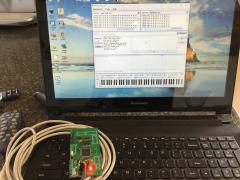
From the album: Mini Core
A successful build of the STM32F4 mini core designed by FantomXR. -
You can find inspiration from the BLM Modules in the SVN. With an STM32F4 core: SRIO with Default MIOS32_PRESCALER_128, a scanline will take 36us. 84/128=0,656Mhz => SPI clock period is 1,52uS Your total scan line is: 1,52 * 24 = 36,57 us For you to know that the SRIO scan a line every ms, then your total scan will take 21ms For better accurate you can write your own module to scan all lines within the 1ms period: 36,57* 21 = 768uS If the remaining time for other processes is not enough(here 1000-768=232us) and your circuit permits it, you can decrease the prescaler to 64, total scan will be 384us... Try to debounce in circuit too ;) What I told you is just some track to explore! it's not a ready-made truth ;) Prototype it and code it before pcb design! ;) Have fun Bruno
-
It needs to implement HID on USB HS(As FS) but it's pin PB12->PB15 which are used for J8/9 https://stm32f4-discovery.net/2014/08/library-31-usb-hid-host-for-stm32f4xx-devices/ Good night! Bruno
-
Yes, Peter requested a TPD-like addition. Still have to test and clear it with the case-master. SEQ V4+ will run also on a Wilba panel if the Core is STM32F4. The previous ideas thread had something like a v5 (e.g. RGB 16x4 matrix) but in the end it was mutually decided to make only subtle hardware changes to put less software support pressure on TK. There's a line driver DB-25 port, so all expansions are external. E.g. Altitude's AOUT, I will probably do one as well or remix my current design LEDs, same as on the Discovery but broken out on the front rear panel. One is acting as a Beat LED, three left for other functions (not assigned yet) Yep! And a stereo jack to boot, so one channel is defined to work as a 0-5V gate. We'll get going as soon as everything's ready :)
-
ans if he ask for what fore then tell him stm32f4 + 2*midi io
-
Some basec question, I have started up the STM32F4 based board, NG installed... Can you help how to configure the connected boards? 1x AINSER64, 1x DIO MATRIX (leds and buttons connected - see enclosed file, 1x MIDI board, 16DOUT via J10A and J10B, 2x AIN via J5A The main question is how to set shift registers of DIOMATRIX and AINSER module and then which HW ID will belong to which button, LED, POT? NG concept.pdf