Search the Community
Showing results for 'STM32F4'.
-
we want to create a small STM32F4 based Board (for example 10x5cm in size), with limited Pins/sockets... this topic has not the the claim to be perfect... all the infos are on the WikiPage WikiPage: http://wiki.midibox.org/doku.php?id=mnmlcore#design_concepts we can edit - one piece of information - and have to possibility to to compare different designs more ease PCB: initial shematic/Board Layout (eagle): MinimalCore.zip taken from: (be aware that this files could be not ready for fabricate!!! - i take no response for any use of it!) PCB: the eagle file above - ported 1:1 to Kicad 5 (which is still in 5.0.0 nightly): NewCoreSTM.zip that this file is not ready for PCB fabricate!) DESIGN Concept: discuss about how a small Core can be used on a small UI (small UI- less space) - also about the point that in most cases we need a midiport, and no optos are onboard till now... (except LPC17 and Core8) please look into the wiki where i already pointed out my view of things
-
From the album: Mini Core
A successful build of the STM32F4 mini core designed by FantomXR. -
You can find inspiration from the BLM Modules in the SVN. With an STM32F4 core: SRIO with Default MIOS32_PRESCALER_128, a scanline will take 36us. 84/128=0,656Mhz => SPI clock period is 1,52uS Your total scan line is: 1,52 * 24 = 36,57 us For you to know that the SRIO scan a line every ms, then your total scan will take 21ms For better accurate you can write your own module to scan all lines within the 1ms period: 36,57* 21 = 768uS If the remaining time for other processes is not enough(here 1000-768=232us) and your circuit permits it, you can decrease the prescaler to 64, total scan will be 384us... Try to debounce in circuit too ;) What I told you is just some track to explore! it's not a ready-made truth ;) Prototype it and code it before pcb design! ;) Have fun Bruno
-
It needs to implement HID on USB HS(As FS) but it's pin PB12->PB15 which are used for J8/9 https://stm32f4-discovery.net/2014/08/library-31-usb-hid-host-for-stm32f4xx-devices/ Good night! Bruno
-
Yes, Peter requested a TPD-like addition. Still have to test and clear it with the case-master. SEQ V4+ will run also on a Wilba panel if the Core is STM32F4. The previous ideas thread had something like a v5 (e.g. RGB 16x4 matrix) but in the end it was mutually decided to make only subtle hardware changes to put less software support pressure on TK. There's a line driver DB-25 port, so all expansions are external. E.g. Altitude's AOUT, I will probably do one as well or remix my current design LEDs, same as on the Discovery but broken out on the front rear panel. One is acting as a Beat LED, three left for other functions (not assigned yet) Yep! And a stereo jack to boot, so one channel is defined to work as a 0-5V gate. We'll get going as soon as everything's ready :)
-
ans if he ask for what fore then tell him stm32f4 + 2*midi io
-
Some basec question, I have started up the STM32F4 based board, NG installed... Can you help how to configure the connected boards? 1x AINSER64, 1x DIO MATRIX (leds and buttons connected - see enclosed file, 1x MIDI board, 16DOUT via J10A and J10B, 2x AIN via J5A The main question is how to set shift registers of DIOMATRIX and AINSER module and then which HW ID will belong to which button, LED, POT? NG concept.pdf
-
after 6 months of blood. sweat and tears, 20m of ribbon cable, a ton of parts soldered, screwed and glued - it’s (almost) done! this midibox build-up is intended to use it for what ever i like. it can be a midi controller for music applications, sequenzer, modular controller, video mixer, lightning desk etc… the sky is the limit! still this is a first test controlling some moogs and plug-ins with open lab's stagelight. thanks to the midibox community for the competent help and documentation. SPECS: CPU - Midibox NG on STM32F4, 4 x DIN, 4 x DOUT, AINSER64, AOUT_NG, MIDI IO - Intel NUC 3.5 GHz Dual Core i7, 32 GB RAM SCREEN - 21.5“ capacitive HDMI touchscreen 1920 x 1080 px - 16 x OLED displays 128 x 64 px HARDWARE - 17 x endless encoder with push - 16 x blue LED buttons - 16 x RGB LED buttons - 6 x bank buttons - 4 x function buttons - resistive XY joystick with push - 2 x 60mm faders EXTENSIONS - 8 x CV out - 2 x DIN MIDI I/O - 32 x analog IN (for pots, faders, sensors) - 32 x digital I/O (for encoders, switches, leds) - HDMI port for 2nd monitor, beamer (4K) - 2 x USB3 in ports (NUC) - 1 USB out port (switch for internal/external cpu) - modular voltage out +/- 12v, 5v all the best roberto ps. how to embed YouTube videos? i dort get it... P.P.S: moderator fixed this
-

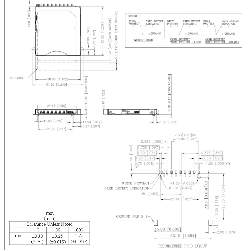
SD-Card-Slot / Socket - Supplier Footprint and interconnection
Antichambre replied to Phatline's topic in Parts Questions
You're welcome. The connection to the stm32f4 is -
 hei searching for a supllier (EU/Austria) for a SD-Slot - like on STM32F4 Core, or even better would be a micro-SD - slot - because i have a size & price topic! i also need a Footprint/lib for it - Eagle or Kicad - or any other Format which can be easy converted to KICAD (thats what i use) --- so anything that is in the standart library of these programs - and is available in EU i found @reichelt https://www.reichelt.de/Connectoren-fuer-Speicherkarten/3M-SDRSMT2MQ/3/index.html?ACTION=3&LA=446&ARTICLE=224937&GROUPID=7432&artnr=3M+SDRSMT2MQ&SEARCH=sd%2Bsockel&trstct=pos_10 and its looks pretty much like the STM32F4 cores socket... (happy that they have a slot now!) Then the interconnection to the core for me is not clear, @latigid on i think you can help - since you have expierience whith your wcore, http://wiki.midibox.org/doku.php?id=wcore_res-sd i have this pin-out: dont know if it is right up to now, and one -i- not connected yet - the CS maybe --- maybe total wrong what i have done... the datasheet from reichelts socket is: qest: are the pinout-Numbers of a Slot Normed? (like on a XLR-Plug, or a Midi-Connector?)
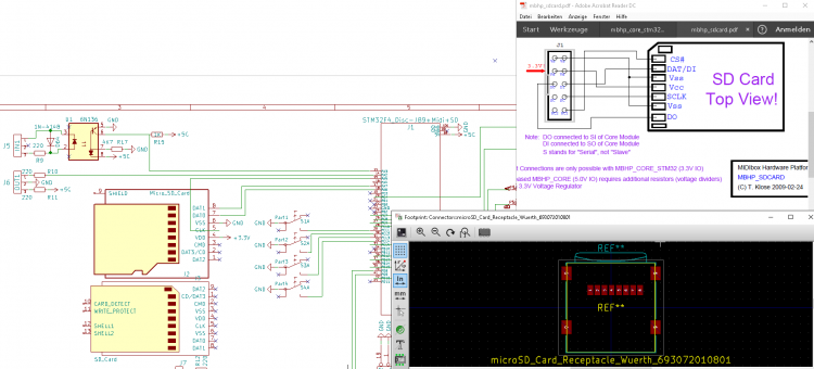

-
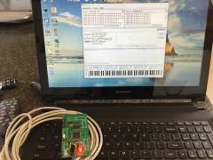
this video 2 my midibox stm32f4 disc
-
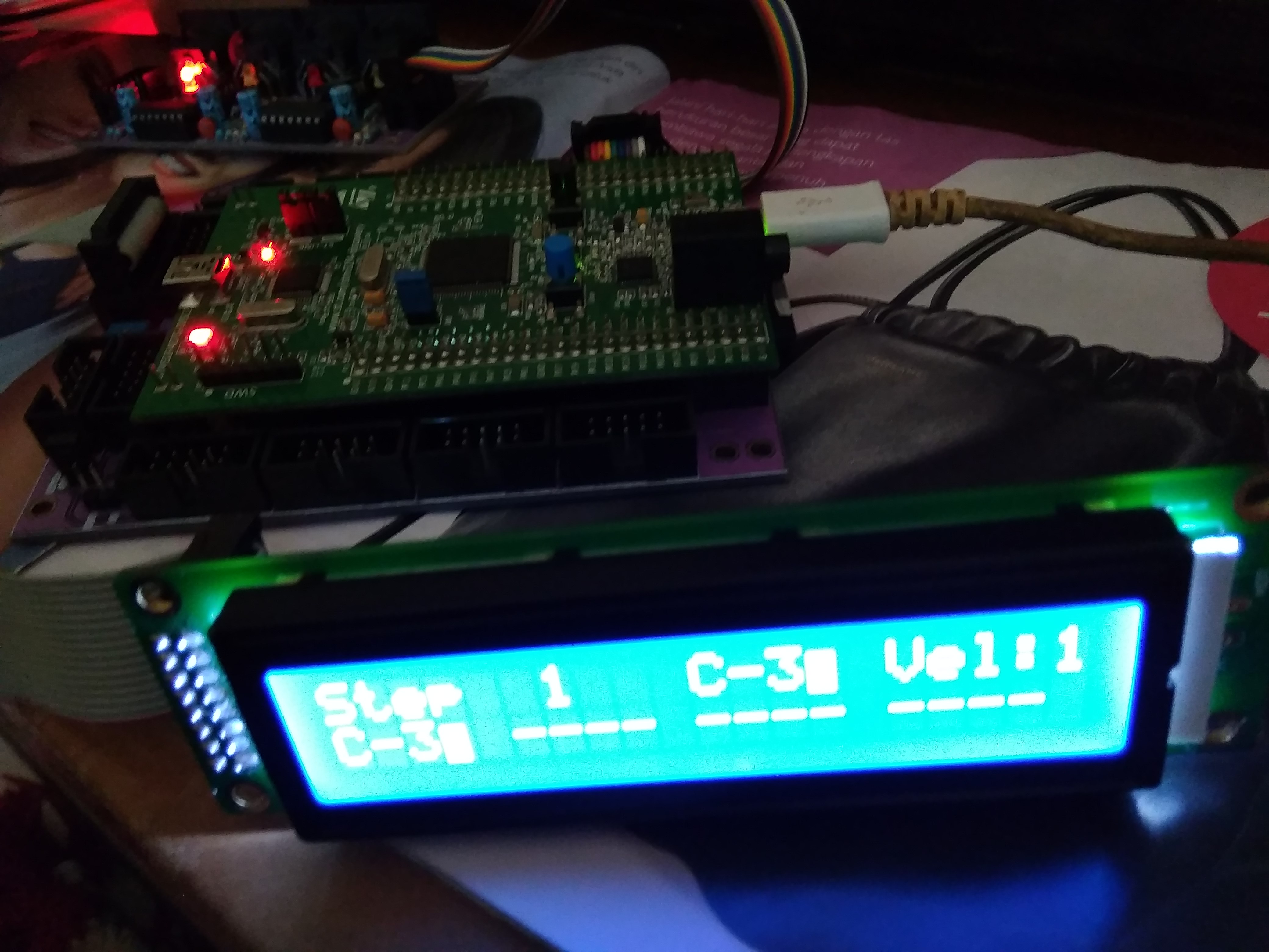
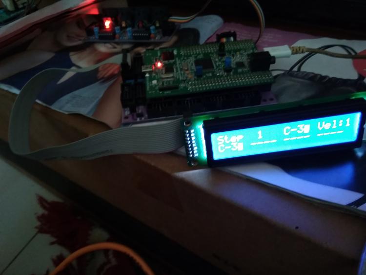
thanks for the time and attention I am a less experienced midibox user, in indonesia, i have built a system midio128 control midi keyboard / organ controller modification organ and button panel button with stm32f4 will and i have followed all the instructions from de ucaps also but when i input hex bootloader filehttp://www.ucapps.de/index.html?page=mios32_bootstrap_newbies.html, also hex midio v3 .19 on lcd 2x 20 has not appeared as in the picture like this, but i have set it like the one in for midi player via sd card module please help it especially regarding mios 32 hex file for midio 128 v3 http://www.ucapps.de/mios32_download.html bundle package like the one in hex seq 4 file for sequncer as i have explained and i sent the picture through this midibox forum this video update :

-
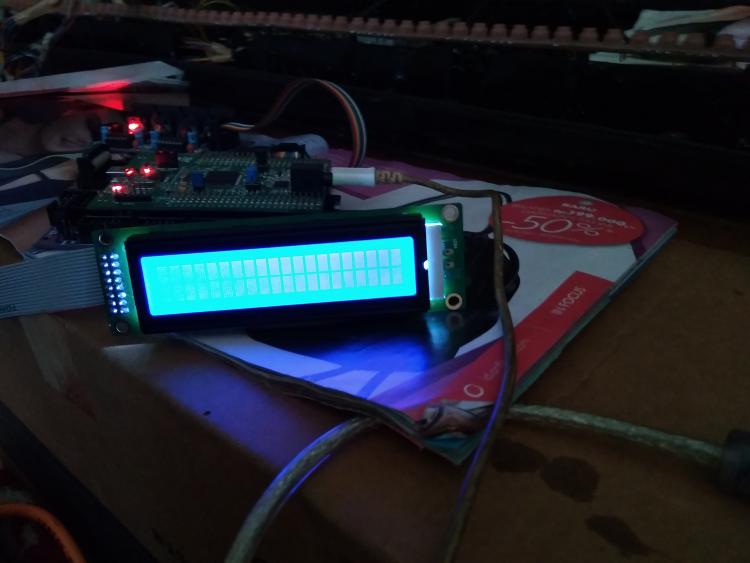
 Thanks for creating a separate topic! Two questions: * Do you see any debug outputs in the MIOS Studio console, when starting up MBNG? * After MBNG has started (even with the display looking bad), can you enter any commands in the MIOS Studio console? E.g. typing "help" should show you a summary of available commands. These two questions should allow us to determine, if MBNG is running properly or is having problems at startup. If the app is not running, please double-check that you are using the correct STM32F4 hex from the midibox_ng.zip package that you downloaded from ucapps. You can also try to put default.ngc and default.ngl in the root directory of the sd-card. These files are provided in the cfg/default directory of the midibox_ng.zip. When the default.ngc is loaded, it should log that in the MIOS Studio console. Good luck! Peter
 -
I apologize for my mistake I am a new and english midibox user with this bad I like that I have to say before him that I have built stm32f4 based following my post with the picture to build midio 128 as in this picture, and this is my test forum:

-
Does anyone have any info for the MB909 sequencer for the 9090 TR-909 clone. I need to know how it was connected to the STM32F4 core board as I only have a wiring diagram for the LPC17 core. Thanks
-
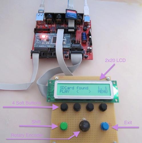
how to geti want like this set stm32f4 disc for mbng core with scs

-
* Did you load the STM32F4 specific version of MB_NG? Other firmwares for other (older) cores might not work. * What are the startup messages in the MIOS Studio console? There should be some DEBUG output when starting MB_NG. * Do you have an SD card with any configuration files inserted?
-
i have built the stibl stc32f4disc midibox correctly and after upload mios studio hex program also seq v4 already appear on my lcd 2x20 with brand not hd447780 (hitachi) but i try to insert mb ng through mios not show in my lcd i please give in suggestion , whether the lcd does not match the driver in mb ng or there is a system that must be in input as shown in my picture

-
Hi, I think I found a bug. I am on V4+.095 with the STM32F4 core. The "Duplicate FX" only works if the receiving channel is different to the one the track is set to. This would make sense if it is set to the same port, but not if set to a different port. So my track is outputting on Out 3, channel 2, I want to duplicate to Out 1, channel 2. Doesn't work, only if i set the duplicate destination to 1, 3, 4 etc. I actually want to use the Duplicate FX to send CC feedback to a NG controller with 2 LRE8x2, so obviously the controller receives on the same channel as it sends. Is there a smarter way to achieve this? Like this you still need to configure anew for each pattern (or make a Preset for each one). Edit: If you set "Additional Channels" to more than 1, the channel with the same number is included, too, but obviously the next one too.
-
This Settings in "mios32_config.h" are working for 0-7A (5a,5b) - i am on a stm32f4 #define MIOS32_AIN_CHANNEL_MASK 0x00ff // AIN define the deadband (min. difference to report a change to the application hook) #define MIOS32_AIN_DEADBAND 31 //7Bit
-
I, sorry my stm32f4 not disply after flash mb ng firmware
-

GM5 driver not supported for STM32F4?
gerald.wert replied to gatesphere's topic in MIDIbox Tools & MIOS Studio
Maybe it is related to the cable bring a USB A type cable and you need the B cable: http://midibox.org/forums/topic/19105-stm32f4-communication-issues-with-mios-studio-no-usb-midi-available/#comment-166624 -
Hi all, I received my STM32F4 board in anticipation of building my SeqV4. I flashed the bootloader with ST-LINK on Win7 x64, and then used MIOS Studio to upload the SeqV4 application. From there, MIOS Studio doesn't want to talk to my STM32F4 anymore -- it sees 4 Midi ins and 4 Midi outs from the Seq, but no combination of those four ports will let me talk to it -- it says 'no response from device' or something similar. The bootloader fail-safe mode works (holding the USER button down on reset keeps it in the bootloader). But I can't communicate to it while it's actually running the Seq app. I think this is because of the known Win7x64 USB MIDI driver issues. But I find " The GM5 driver is currently not supported for the MBHP_CORE_STM32F4 module, but it's planned to provide it in future!" on the MIOS32 download page... so this driver won't help in this situation? I'd like to keep the four USB Midi In/Outs because I'll be using this thing with Linux mostly, but I can't get MIOS_Studio working on my Arch Linux install at the moment. The pre-compiled version didn't work, and compiling it from source caused me some GTK errors that I haven't sussed out. I'd also like to be able to update the Seq App in the future without having to disassemble my device to get to the button... Any help? I'll probably continue debugging the MIOS_Studio app on Linux to avoid Windows as much as possible, but I thought I'd ask here if there were any suggestions.
-
help needed FPU not working on STM32F4 with MIOS32
Antichambre replied to loeller's topic in MIOS programming (C)
I was looking for something else and I found this: https://github.com/openAVproductions/openAV-stm32f4/tree/master/03_float -
So, digging around a bit, if I wanted to build the Mongbox version of the SeqV4 (that is, no modifications), I'd need: - 1x STM32F4 Core board - 2x MIDI IO boards - 1x Wilba CS board Plus all the gubbins to fill those boards out. And the STM board to plug into the core. And 2x screens. Sound about right? Just making sure I'm not missing anything here. (Also, sorry for derailing my own thread...)