gerald.wert
-
Posts
131 -
Joined
-
Last visited
-
Days Won
2
Content Type
Profiles
Forums
Blogs
Gallery
Everything posted by gerald.wert
-
I made a write up on how to get the new D version running. Works no problem. The only issue is if you are using the PCB from Smash LPC slightly moved the pins several versions back. Did not change the pin order just made it challenging to solder. If you have the PCB and line everything up before you solder you should be good. You can likely get the code running on the teensy. I would expect to have to look at the timing and pin assignments to get it working along with memory mapping. It really depends if they have done things much different from ST. The teensy 3.x would likely be you best bet if you have one already to mess about with. It would have the same m4 processor and 3 serial, 2 i2c and 2 spi. If there are not conflicts and all those peripherals are actually available that would be a nice platform. I am not sure you are really gaining anything over a stm32f4 there though. They cost about the same. The only possible advantage I see there is a smaller footprint and maybe since it does not have the gyro maybe less conflicts depending how teensy wired things up on the board. The challenges would be the M4 crystal clock is not 168 on any of the 3x teensy so that would need to be adjusted for in porting. Maybe it would be easier to replace the crystal on the teensy. Not sure if that would break compatibility with programmers though. I have ported some code from one avr to another where it was just changing pin mapping but this would be a lot more involved. There is a lot of time saved with using a platform that is already up and running and bug tested. If you have the time and interest you should go for it though. Would be great addition for the community.
-
There is a random pattern generator in the midibox sid that might fit your need. It sounds like you have something really specific in mind and if you can lay it out programmatically you may be able to implement it in Midibox NG. NG gives you a platform where you can script what you want your application to do in a text configuration file. You would need to build a core and a midi io for what it sounds like you want to do. Take a look at the Midi box NG user manual and see if it is what you are looking for.
-
The 2x16 with the right controller would be a great tool idea for testing. I would triple check your wiring as well. It is odd that you are getting only one row of dark characters. Normally they should both be lit with the same amount of contrast. The darkness of the both rows should be adjustable by the contrast pot equally at the same time. If it is too dark you will not be able to see the characters. The same if it is too light. the contrast should work in this way regardless if the controller is compatible or not. If the controller is not compatible or there is a soldering or component issue you will have the additional issue you mention of lack of characters or possible gibberish on the screen. If you are using header connectors it would be possible to get one backwards or reversed. If this were the case you might possibly have a data line connecting to the contrast connector. That may be cycling the contrast at a rate where only one line is being lit full contrast. If the wiring is good and contrast is working properly on the single line it is most likely you have a bad LCD. Good luck! Gerald
-
Thanks, I am interested I sent you a message.
-
Looking to buy a Seq v4 PCB.
-
Is your jumper on the core set to 5 volts? If there is no jumper or it is set to 3.3 volts it will not work.
-

SSM2044 line level? VPP? Overdrive Input?
gerald.wert replied to Phatline's topic in MIDIbox User Projects
The filter input is 47k and the output is 10k It is not balanced but stereo if you are looking at the schematics so is consumer not pro. It also should not need a DI. I use a unbalanced 1/4" cable and plug in my mixer 1/4" line inputs. Watch the impedance and pF of the 1/4 cables you are using. If you had to run the cable a long way or were picking up noise I would try a balanced xlr with a DI as close to the filter as needed or have a small mixer to plug in and send from the balanced outs of the mixer. Either of these should work well especially if you are having to run a few hundred feet through an analog snake. -
 Nice setup. I have been thinking about how to make my rig portable and durable at the same time.
 -
Smash TV has better quality but may be newer revision of most of the boards on his site. His stuff has solder mask, through hole plating and silkscreen. Mikes board and components were good quality as well just a more basic PCB. If you look at the Kit section there you should see photos. Sounds like Sparx may have some for you though.
-
Have you tried Mike's shop? He has them listed http://www.mikes-elektronikseite.de/mshop_englisch/index.htm He was super helpful and got me a board a few months ago.
-
You can spend a lot of time routing traces in a cad program. If you etch your own PCB you also need to consider drill time. Limited drilling can be an advantage of strip or pad per hole board in a proto phase or a one off. You have a lot more freedom in part placement when making a board in cad. If you are planning more that one it is definitely worth cad time. +1 to also having more than one board, that will make your life a lot easier when you start to trouble shoot it in addition to the lower cost.
-
The Veroboard is really good quality. Their most durable is the epoxy board. It is much more durable than the paper or phenolic stuff. You can buy it direct : https://veroboard.com/product-category/the-veroboard-products/view-by-material/epoxy-fiber/ It comes up on Amazon and ebay too. That is where I normally buy it but I do not see a good listing right now. If you have ever worked with fiber glass before be sure to protect yourself when cutting it. I wear disposable gloves mask and safety glasses. Use a rotary tool with a fiber cutoff disk to cut it. It cuts a lot faster if you cut down a row with the holes in it and they make a nice guide. Also try not to cut it to fast so it does not heat up and smoke. Making a shallow first pass and going back over it a few times keeps it from smoking. It does take some time making the cuts to lay out the circuit but I find it is faster than cutting and stripping so many extra wires. It may or may not be faster than etching a board it depends on how many holes you have to drill and how much time you have to spend laying it out in the cad program. Another design tip if you are using encoders you can run you ground bus below the encoders on a strip and jump over to it with a resistor trimming.
-
You can use strip board either vertically or horizontally to reduce you wiring if it makes sense for your layout. It should cut your individual wires almost in 1/2.
-
I have a 4L and have been using the juice BLM as a faster more accurate way to input notes. It would be really handy to have a horizontal zoom feature. If the bar display at the bottom were clickable. No boxes =100% zoom and the grid is in its normal current mode displaying 16 1/4 notes. One box lit and you get 200% zoom and you get 16 1/16 notes of the section of the bar you have selected displayed. Selecting two consecutive boxes for 150% zoom to get 16 1/8 notes on the grid of the two adjoining boxes of the bar selected. Maybe there is already a way to do this but all I have been able to come up with in the manual and forums is using a full seq version 4 to set note length with the jog wheel or possibly manually recording in the sequence either from software or another midi device.
-
I would be up for 50 if that gets us closer to an order.
-
SEQ 4LMKii front panel compleatly dead any ideas? (Solved)
gerald.wert replied to gerald.wert's topic in MIDIbox SEQ
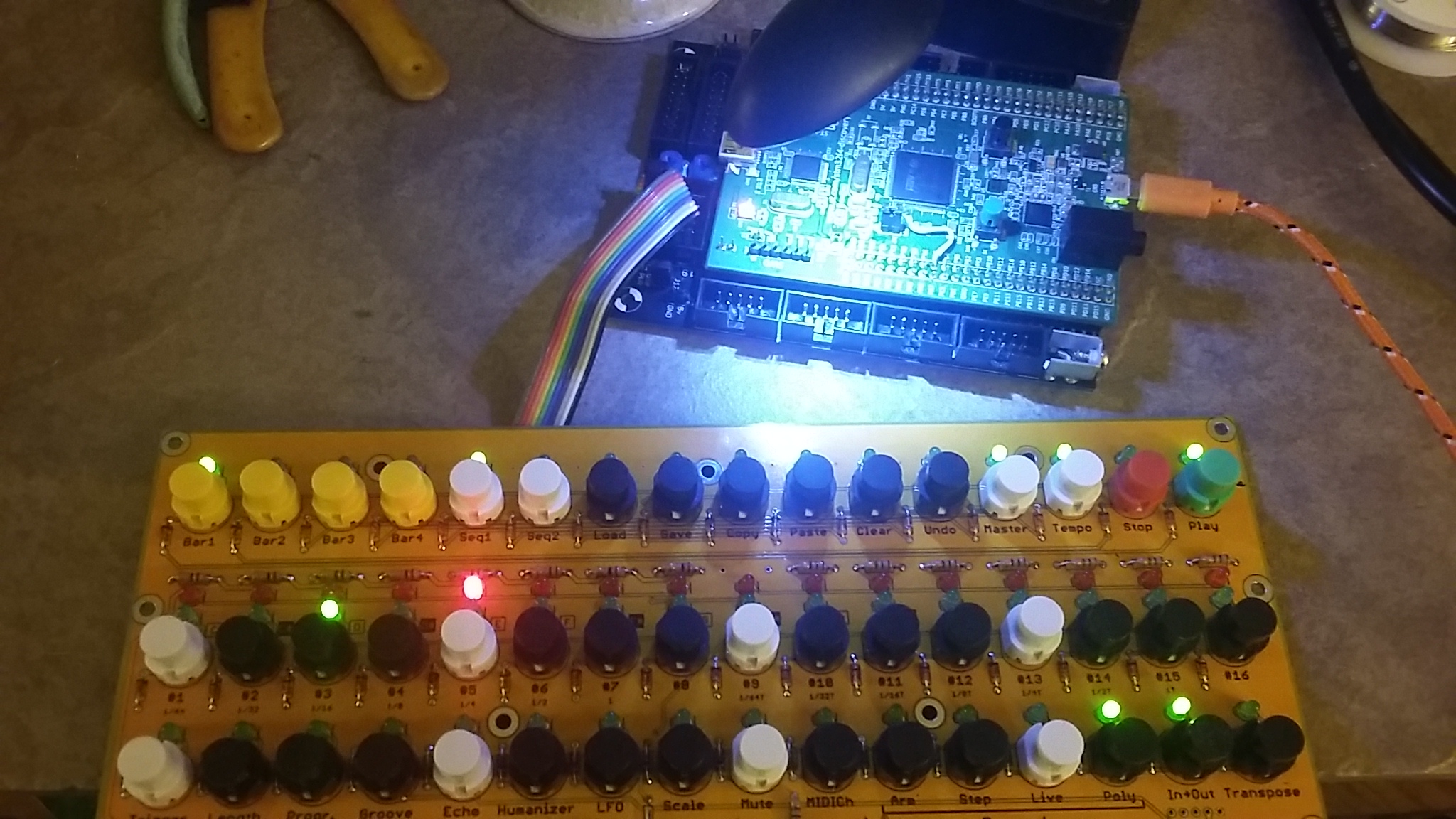
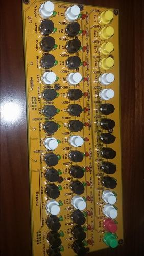
Not wanting to have to solder and remove a chip more than once I decided to just replace IC2 with a new IC as well since it was already off the board. I was not feeling lucky. I also removed the test grounding jumper and after soldering in the new IC we have buttons and lights! I used the script Latigrid-on posted above to test the BLM at this point and all buttons and lights worked. The picture is with the SEQ4L firmware loaded and running. I am not sure what cause all the trouble with the IC. It may have been overheating, possibly static or all the moving around the board got with all the testing of the initial core issues. My SMT technique is a lot better now and that is a good thing!
-
SEQ 4LMKii front panel compleatly dead any ideas? (Solved)
gerald.wert replied to gerald.wert's topic in MIDIbox SEQ
This is the code I used in NG to test with the jumper connected: # Reset to default RESET_HW # EVENTs EVENT_BUTTON id= 1 fwd_id=LED:1 type=NoteOn chn= 1 key= 36 range= 0:127 offset= 0 ports=1000100000001000 lcd_pos=1:1:1 label="^std_btn" EVENT_BUTTON id= 2 fwd_id=LED:2 type=NoteOn chn= 1 key= 37 range= 0:127 offset= 0 ports=1000100000001000 lcd_pos=1:1:1 label="^std_btn" EVENT_BUTTON id= 3 fwd_id=LED:3 type=NoteOn chn= 1 key= 38 range= 0:127 offset= 0 ports=1000100000001000 lcd_pos=1:1:1 label="^std_btn" EVENT_BUTTON id= 4 fwd_id=LED:4 type=NoteOn chn= 1 key= 39 range= 0:127 offset= 0 ports=1000100000001000 lcd_pos=1:1:1 label="^std_btn" EVENT_BUTTON id= 5 fwd_id=LED:5 type=NoteOn chn= 1 key= 40 range= 0:127 offset= 0 ports=1000100000001000 lcd_pos=1:1:1 label="^std_btn" EVENT_BUTTON id= 6 fwd_id=LED:6 type=NoteOn chn= 1 key= 41 range= 0:127 offset= 0 ports=1000100000001000 lcd_pos=1:1:1 label="^std_btn" EVENT_BUTTON id= 7 fwd_id=LED:7 type=NoteOn chn= 1 key= 42 range= 0:127 offset= 0 ports=1000100000001000 lcd_pos=1:1:1 label="^std_btn" EVENT_BUTTON id= 8 fwd_id=LED:8 type=NoteOn chn= 1 key= 43 range= 0:127 offset= 0 ports=1000100000001000 lcd_pos=1:1:1 label="^std_btn" If you are connected to the core with mios studio you should see the button presses displayed in mios studio. There was still nothing input from any of the buttons. This confirmed IC1 was bad. I replaced it with a fresh IC and the buttons finally came to life. -
SEQ 4LMKii front panel compleatly dead any ideas? (Solved)
gerald.wert replied to gerald.wert's topic in MIDIbox SEQ
Thanks Latigrid-on for all the great suggestions on where to look to trouble shoot. I finally got everything sorted out. Since nothing was working I decided to break it down into simpler blocks and work through them one at a time. I removed IC2 to accomplish this. This way I could just test IC! and make sure it was working properly. With IC2 removed you can manualy select any of the 6 rows of 8 buttons by grounding the switch pin that IC2 normall would. Here is the pin I chose to ground to test with. I chose to use the pad at the switch and to run the jumper through the mounting hole on the board to the ground on the DIH box. I figured these two places would be the most durable places to solder and I should not have to worry about lifting traces there.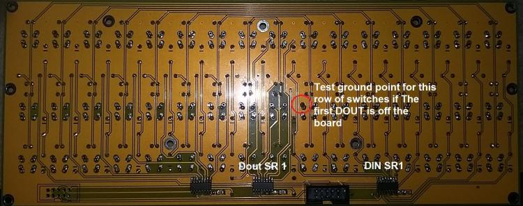
-
SEQ 4LMKii front panel compleatly dead any ideas? (Solved)
gerald.wert replied to gerald.wert's topic in MIDIbox SEQ
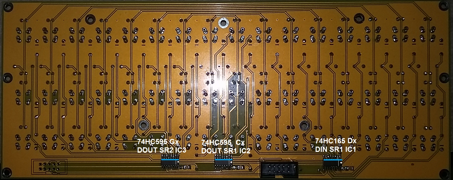
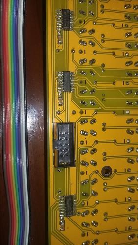
This is a picture of the board with the chip position and labels. I also marked the angled edge of the chips with a blue line. This helps show where pin 1 lives.
-
SEQ 4LMKii front panel compleatly dead any ideas? (Solved)
gerald.wert replied to gerald.wert's topic in MIDIbox SEQ
Here is my circuit for the bread board if anyone else needs to test a core. I would recommend testing with separate DIN and DOUT first to keep testing simpler. I found it a lot easier to look at and build just one position of the BLM. the full map is super useful for tracking down a bad component to testing a row or column.
-
STM32F4 SDCARD Reading CID failed with status -256! Solved
gerald.wert replied to gerald.wert's topic in MIDIbox SEQ
Verowire would be a lot better. I was going to use some wire wrap or the verowire but could not find where either the rolls had gotten off to. The ribbon wire worked but is just so big compared to the pin. I debated some solid telephone wire but decided the advantage to the ribbon wire is that it is stranded so hopefully will put less strain on the pin. ST said that the processor on the board does not match production to what they install on the discovery boards and that I would have to go back to the person I bought it from. I looked it up and I actually had bought it on amazon listed as new with a gift card. Basically just stuck with it now. It was a bit disappointing ST did not stand behind their product but also understand their point of it being tampered with. Glad I went ahead and fixed it instead of waiting a week or more on their refusal of support. -
SEQ 4LMKii front panel compleatly dead any ideas? (Solved)
gerald.wert replied to gerald.wert's topic in MIDIbox SEQ
Thanks for the ideas on testing. Yes there are no lights on the CS on startup and no response from any button pushes either. I am going to test it some with NG when I get a chance. I built a small bread board and put a 595 and a 165 on it with some buttons and leds. I figured it would be good to have peace of mind knowing everything works ahead of the CS. Cable is good. SD cards are good. DIO is good DIN is good. Cable header boxes are in the right way. Both cores the stm32f4 and lpc17 are fully working. I tested some of the leds and they are testing normal and not reversed. I did find that the 74hct541on the stm32f4 core was not working and preventing the DOUT chain from functioning on that core. Interesting that the DIN chain was good on it. I replaced it and it is running properly with the breadboard. On to testing the CS some more now that I know everything is working ahead of it. -
SEQ 4LMKii front panel compleatly dead any ideas? (Solved)
gerald.wert replied to gerald.wert's topic in MIDIbox SEQ
I have been doing more testing and I am not sure the CS board is the issue. I did find a missed solder joint on the board on one of the diodes but that should only affect one switch and had no affect fixing it. I did a quick bread board with a 74HC165 and it looks like there is a possible mapping issue though. When pressing button on pin 7 [74634.514] [SEQ_UI_Button_Handler] Button SR:25, Pin:7 not mapped, it has been pressed. [74634.619] [SEQ_UI_Button_Handler] Button SR:29, Pin:7 not mapped, it has been pressed. [74634.698] [SEQ_UI_Button_Handler] Button SR:25, Pin:7 not mapped, it has been depressed. [74634.742] [SEQ_UI_Button_Handler] Button SR:29, Pin:7 not mapped, it has been depressed. when pressing button on pin 6 [74730.176] [SEQ_UI_Button_Handler] Button SR:25, Pin:6 not mapped, it has been pressed. [74730.319] [SEQ_UI_Button_Handler] Button SR:29, Pin:6 not mapped, it has been pressed. [74730.360] [SEQ_UI_Button_Handler] Button SR:25, Pin:6 not mapped, it has been depressed. [74730.404] [SEQ_UI_Button_Handler] Button SR:29, Pin:6 not mapped, it has been depressed. When pressing button on pin 2 [76086.564] [SEQ_UI_Button_Handler] Button SR:25, Pin:2 not mapped, it has been pressed. [76086.608] [SEQ_UI_Button_Handler] Button SR:29, Pin:2 not mapped, it has been pressed. [76086.783] [SEQ_UI_Button_Handler] Button SR:29, Pin:2 not mapped, it has been depressed. [76086.828] [SEQ_UI_Button_Handler] Button SR:25, Pin:2 not mapped, it has been depressed. I think that it would be returning matrix values and not SR values or the SR values should be activating what they are mapped to by matrix assignment if the matrix is mapping to ports above 23 like it looks like it may be doing. . I have not been able to find the matrix mapping part looking in the code to have a better sense of it. I can turn off the BLM and map a button to say the start/stop buttons with a SR 1 x mapping and the sequencer starts and stops. I do not have any 74HC595 on hand to test the DIO select or leds. I have a spare soic 595 I will try soldering some jumpers to the legs to be able to test with it. Additionally if I update button mapping from MX Y mapping to say SR 25 pin 6 and 7 to play stop as returned above things work for the buttons mapped. Same thing with NG it does not see the CS but I think that is my not mapping the BLM correctly. NG works as expected with the breadboard. This is the NG script I put in the DEFAULT.NGC file for testing: # BLM8x8 without button/LED emulation RESET_HW LCD "%C@(1:1:1)Simple 8x8 BLM" # HW definitions: DIN_MATRIX n= 1 rows=8 inverted_sel=0 sr_dout_sel1=1 sr_din1=1 DOUT_MATRIX n= 1 rows=8 inverted_sel=0 sr_dout_sel1=1 sr_dout_r1=2 # note: actually the sr_dout_sel1 in DOUT_MATRIX could be removed, # since DIN_MATRIX already outputs the selection pulses there # this is just for the case that somebody copy&pastes the definition... # which events should be sent by the button matrix? # the key number will be automatically incremented depending on the button index of the matrix EVENT_BUTTON_MATRIX id=1 fwd_id=LED_MATRIX:1 type=NoteOn key=36 lcd_pos=1:1:1 label="Matrix1 Pin %2p %b" Yes the constant restarting on the stm32f4 gets old. the LPC does not require the restarting MIOS if you reset from console. That is a nice option. I am pretty sure the cable is good it works going to the bread board. -
SEQ 4LMKii front panel compleatly dead any ideas? (Solved)
gerald.wert posted a topic in MIDIbox SEQ
I recently completed a SEQ 4LMKii. I am getting power to the cs and I have tested for bridged joints and can not find any shorts with the meter. It is dead on my stm32f4 core and my LPC core. I have the SRIO v4l hardware file in the root folder the SD card and it is showing as valid. Sequencer seems to run properly from the console on either core. It says MBSEQ_C.v4 and MBSEQ_BM.V4 are missing but they are in the sessions folder for both STM and lpc. .J15 is set to 5v. [39012.596] sdcard [39012.568] SD Card Informations [39012.568] ==================== [39012.568] -------------------- [39012.568] CID: [39012.568] - ManufacturerID: [39012.568] - OEM AppliID: [39012.568] - ProdName: SL08G [39012.568] - ProdRev: 128 [39012.568] - ProdSN: 0xe8631ddd [39012.568] - Reserved1: 241 [39012.568] - ManufactDate: 266 [39012.568] - msd_CRC: 0x19 [39012.568] - Reserved2: 1 [39012.569] -------------------- [39012.569] -------------------- [39012.569] - CSDStruct: 1 [39012.569] - SysSpecVersion: 0 [39012.569] - Reserved1: 0 [39012.569] - TAAC: 14 [39012.569] - NSAC: 0 [39012.569] - MaxBusClkFrec: 50 [39012.569] - CardComdClasses: 1461 [39012.570] - RdBlockLen: 9 [39012.570] - PartBlockRead: 0 [39012.570] - WrBlockMisalign: 0 [39012.570] - RdBlockMisalign: 0 [39012.570] - DSRImpl: 0 [39012.570] - Reserved2: 0 [39012.570] - DeviceSize: 15159 [39012.570] - MaxRdCurrentVDDMin: 0 [39012.570] - MaxRdCurrentVDDMax: 0 [39012.570] - MaxWrCurrentVDDMin: 0 [39012.571] - MaxWrCurrentVDDMax: 0 [39012.571] - DeviceSizeMul: 240 [39012.571] - EraseGrSize: 31 [39012.571] - EraseGrMul: 28 [39012.571] - WrProtectGrSize: 0 [39012.571] - WrProtectGrEnable: 0 [39012.571] - ManDeflECC: 0 [39012.571] - WrSpeedFact: 2 [39012.571] - MaxWrBlockLen: 9 [39012.571] - WriteBlockPaPartial: 0 [39012.571] - Reserved3: 0 [39012.571] - ContentProtectAppli: 0 [39012.572] - FileFormatGrouop: 0 [39012.572] - CopyFlag: 1 [39012.572] - PermWrProtect: 0 [39012.572] - TempWrProtect: 0 [39012.572] - FileFormat: 0 [39012.572] - ECC: 0 [39012.572] - msd_CRC: 0x57 [39012.572] - Reserved4: 1 [39012.572] -------------------- [39012.572] [39012.573] Reading Root Directory [39012.573] ====================== [39012.573] Retrieving SD Card informations - please wait! [39012.573] SD Card: '': 3382 of 3384 MB free [39012.574] [......a] 00/00/-20 00:00:00 AM 22702 MBSEQ_HW.V4 [39012.574] [.....d.] 00/00/-20 00:00:00 AM <DIR> 0 SESSIONS [39012.574] [......a] 00/00/-20 00:00:00 AM 10293 MBSEQ_HW.V4L [39012.574] [39012.574] Checking SD Card at application layer [39012.574] ===================================== [39012.574] Current session: /SESSIONS/DEF_V4L [39012.575] File /SESSIONS/DEF_V4L/MBSEQ_B1.V4: valid (64 patterns) [39012.575] File /SESSIONS/DEF_V4L/MBSEQ_B2.V4: valid (64 patterns) [39012.575] File /SESSIONS/DEF_V4L/MBSEQ_B3.V4: valid (64 patterns) [39012.575] File /SESSIONS/DEF_V4L/MBSEQ_B4.V4: valid (64 patterns) [39012.575] File /SESSIONS/DEF_V4L/MBSEQ_M.V4: valid (128 mixer maps) [39012.575] File /SESSIONS/DEF_V4L/MBSEQ_S.V4: valid (64 songs) [39012.576] File /SESSIONS/DEF_V4L/MBSEQ_G.V4: valid [39012.576] File /SESSIONS/DEF_V4L/MBSEQ_BM.V4: valid [39012.576] File /SESSIONS/DEF_V4L/MBSEQ_C.V4: valid [39012.576] File /MBSEQ_C.V4: doesn't exist [39012.576] File /MBSEQ_BM.V4: doesn't exist [39012.576] File /MBSEQ_HW.V4L: valid [39012.576] done. I get some additional errors on a reset from terminal on the LPC board: [38687.653] reset [38689.799] Init DHCP [38689.899] [network_device_init] PHY initialized [38692.821] Loading session DEF_V4L [38692.846] [SEQ_FILE_HW] ERROR: unknown STEP_TPM_* name 'COLUMNS_SR_L'! [38692.847] [SEQ_FILE_HW] ERROR: unknown STEP_TPM_* name 'COLUMNS_SR_R'! [38692.847] [SEQ_FILE_HW] ERROR: unknown STEP_TPM_* name 'ROWS_SR_GREEN_L'! [38692.849] [SEQ_FILE_HW] ERROR: unknown STEP_TPM_* name 'ROWS_SR_GREEN_R'! [38692.849] [SEQ_FILE_HW] ERROR: unknown STEP_TPM_* name 'ROWS_SR_RED_L'! [38692.850] [SEQ_FILE_HW] ERROR: unknown STEP_TPM_* name 'ROWS_SR_RED_R'! This is with the version 086 firmware for the LPC board. I am running version 088 on the stm32F4 board and it does not reset without hanging so I loose what ever the boot messages would be. This seems to be a stm thing as it behaves the same with the regular seq firmware or the NG firmware. Might be windows related. restarting MIOS brings tings back up but you miss any boot messages.
-
Strip board if you align it properly will save you a lot of wiring as you can set all your grounds on one of the strips. That way you do not have to run two wires to each light or switch. You will spend time cutting the traces with a razor knife though to lay out your circuit. The DO and DI boards have separate grounds. I would keep them separate to keep the noise down and to make trouble shooting easier.