

nebula
-
Posts
943 -
Joined
-
Last visited
-
Days Won
4
Content Type
Profiles
Forums
Blogs
Gallery
Everything posted by nebula
-
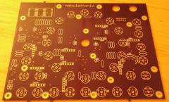
From the album: nebula-circle seq
Here's the front of the PCB from Laen's weekly bulk order. The solder mask is a sexy purple, but this pic is snapped with no flash, the pic looks a bit brownish -
The conduit is a very interesting idea for an enclosure. I would love to see all your handywork inside, but I guess it doesn't really come apart like a typical case, so it might be hard to take good pictures. This is easily one of the coolest MB-SID builds out there. Very nice work.
-
The TR-909 still has a global accent, which offers further dynamic levels. So as an example, the dynamics output might look would be something like this: soft note velocity = 48 loud note velocity = 96 accented soft note velocity = 72 accented loud note velocity = 128 BTW the best way to permanently connect a 9090 board to a MIDIbox 808 sequencer would be to skip MIDI and use the hardware triggers. Otherwise, you have a bit of latency to deal with. Besides the trigger, each drum voice on the 9090 also has a velocity CV input, so I don't know if we'd need an AOUT or if we could use the multiplexed resistor-matrix DAC on the 9090 board. I plan to order my 9090 board this week.
-
The TR-909 sequencer brought a really cool new feature that was missing in the 808 and 606 before it: dynamics. Aside from the global accent, many of the instruments allowed two distinct dynamic levels on each step. To look at how this worked from a user perspective, first let's look at the TR-808: if you have a blank pattern and press one of the step ("GP") buttons, its corresponding LED lights up and you have activated a drum trigger on that step. Press the button again, the LED turns off, and you have turned off the drum trigger on that step. That's two different states: off and on. On the TR-909, the beginning is similar: the LED for a given step is off when there is no trigger programmed. Press the GP button for a given step, and the LED comes on, but at 1/2 brightness. You have activated the trigger, and the note will play on that step, at 1/2 dynamics. Press the GP button again, the LED comes on at full brightness, and the step will trigger with full dynamics. The step will turn off when you press the button a third time. That's three different states: off, half, and full. There has been some discussion of a hypothetical "MB-9090" in which the MIDIbox 808 software is used to control a 9090 board (from Trevor Page) to make a TR-909 clone. It's a great idea, except that AFAIK TR-909 dynamics can't be realized with the current software. I suspect that modifying the MIDIbox 808 software to allow two different dynamic levels on each step is feasible. But the hardware problem of dimming the LEDs to provide visual feedback of the dynamics per step is a problem - the TR-909 uses PWM to dim the LEDs, and it has been stated elsewhere that 8-bit MIOS can't do PWM dimming effectively due to the required CPU cycles. Perhaps a solution to this would be to use 16 additional DOUT pins, which the builder could use to either light the same LEDs at half brightness (via highter-value resistors) or a second set of LEDs to indicate the lower dynamic level per step. The two-level-dynamic feature would need to be something that can be defined, per instrument, in the setup.asm file. Also, the level would need to affect MIDI velocity, and likely a CV as well. Anyway, this is just a concept. I'm not (yet) a MIOS programmer so I suggest this capability with all modesty, as right now I do not have a clue where one would even begin to make something like this a reality. But at this point I think it's important that the idea gets out there, because it is the only thing standing in the way of making the world's first fully featured TR-909 clone.
-
worked for me and i wasn't signed in to Google
-
Thanks, but the panel I have forms 3 sides of the enclosure, and the surface is textured, so I don't think I'd use vinyl on this case.
-
Electruck, how did you get the printing on your panel?
-
@Electruck: WOW! +1 FREAKIN AWESOME. Nice work. @Jef: I'm expecting delivery of my control surface pcb this week. I wanted to make my own boards but my oddball layout and space constraints caused me to get it professionally manufactured. It's really not unusual as MIDIbox projects go ... it's just a PIC-based core, some DIN modules wired to buttons and encoders, some DOUT modules wired to LEDs, and optionally 1 display and 1 pot, both wired directly to the core. It doesn't matter what DIN and DOUT pins get wired to what buttons, except that the 16 "GP" sequencer LEDs and buttons need to be wired to consecutive pins. You define which buttons are connected to which pins. The MIDIbox 808 is listed as a "project" on the uCapps.de page. You can use additional DOUTs for analog trigger outputs and/or a 3-digit LED display of BPM. Download the app, unzip it and have a look at the setup file. It will become much clearer.
-
Thanks Wilba ... I actually already contacted him. He's not able to do it in the immediate future, unfortunately.
-
I was just looking at mouser.com and found some spacers that are 9 mm (like http://ca.mouser.com/ProductDetail/Harwin/R30-6010902/?qs=sGAEpiMZZMtnzxi%2fA5nO1fVZufCSfDRrenG5OZuXLJg%3d ), but I didn't take the time to check that they have an internal thread. You could also use something like this: http://ca.mouser.com/ProductDetail/Harwin/R30-3001002/?qs=%252bk6%2f5FB6qrkuRvrGTPmTGA%3d%3d Instead of using screws to hold the board down you'd use nuts, and a nut driver. If you end up going with 8 mm spacers, you could shim the board a bit using washers. It would be a bit of a nuisance to assemble though.
-
Beautiful, minimal panel. Less is definitely more. Very nice.
-
desoldering is the real art, isn't it? At work I have a powered desoldering iron. At home I recommend either using a sold-a-pullt with your regular iron, or else a desoldering iron with a rubber vacuum bulb. http://www.elexp.com/sdr_0822.htm http://www.elexp.com/sdr_0849.htm both are pretty cheap. I find braid only good for smt or non-plated holes. Usually at home I use the bulb iron. Start with a fully soldered joint. If you have previous unsuccessful attempts to desolder, fully fill the holes with solder again. Before applying the iron to the board, squeeze the bulb fully. Then put the iron on the solder joint. In a second or two the solder will melt. Do not press down hard against the board or else you might lift the pad. Move the iron back and forth or in a circular motion as you quickly release the bulb. Do not stop moving the iron! You want the lead to be moving while you suck the solder out and immediately remove the iron. If there is still a little solder left in the hole, the lead movement will help prevent the solder from bonding to the component lead. Now put your finger on the component (in your case the resistor network) and wiggle it a little while you look at the lead on the other side of the board. Does the lead wiggle? If so, good job! If not, wait for the hole to cool and lightly prod the lead with your fingeernail or blunt instrument. Hopefully the lead will work free easily. Do not apply force or you can damage the board. Maybe you can't work the pin free. Don't worry. Move on to the next pin, and try again, starting from a fully soldered joint. Keep doing this until you've finished every pin. Ideally the component will just fall out, but maybe you have 1 or two pins that are still sticking. You can try to apply heat to one hole while gently wiggling the component. Keep wiggling it even after you've removed the heat. When the trace amounts of solder in the hole harden back up, they will most likely not bond to the pin. I'm pretty experienced with this, so I'm confident to do it without damaging a board. In the past I've ruined my share, so if you're unsure, you're better off cutting the component off and replacing it. You want to avoid wiggling or moving the solder joint when it's hot but the heat has not transferred to the solder. In that case the only thing that will have any flex will be the adhesive that bonds the copper to the board, and that's how you lift pads and traces. Good luck.
-
So I'm working on a small front panel (5.5 x 6.5 inches) for my MIDIbox 808 project. It's going into a Hammond 1456FE1 case. http://www.hammondmfg.com/pdf/1456FE1.pdf I want to drill the front panel for the buttons etc, then get somebody to silkscreen my design on it in black only. It's already coated with a lightly textured paint. Anybody want to take this on, or direct me to somebody? I'm willing to pay for time and materials. I would prefer to deal with somebody in Canada or USA.
-
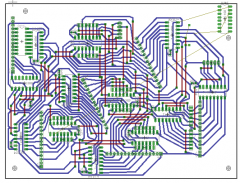
From the album: nebula-circle seq
The DIN/DOUT was to be connected to this PCB, "sammich" style, using SIP headers. This board was also designed for home etching. I quickly came to realize that this was going to require a ridiculous amount of drilling, and too many wires on top of my single-sided board. (Red = top wires, blue = bottom traces) -
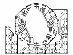
From the album: nebula-circle seq
This was my original design for the control surface PCB, designed for home etching. I since decided to include the control surface and DIN/DOUT on a single PCB, externally fabricated -
$29 - kit or pre-assembled?
-
Nice! Is this a kit? Can you get crazy glitching/aliasing using extreme values? Do you have a secret desire to make a control surface? The price is awesome, but the shipping is crazy... I'm thinking about ordering a few and splitting the cost between some friends.
-
I just re-read your original post. Just wondering: you say you want to rebuild instead of building a whole new PSU ... but once you've replaced the transformer and the regulator, the only thing really left is the enclosure and just a few support parts. Why not simply start fresh?
-
For a transformer I'm ordering a Hammond 266M18 tomorrow. It has dual 9V windings. It is available from Digi-Key and from Newark, maybe Mouser. Also, Canadian electronics reseller Electro-Sonic now has an American presence, check their web site at www.e-sonic.com - maybe their price is better. I'll be using one 9V winding directly for the AC, and I'll be using a regulator on the other winding to give 5V. The regulator is LM323K, which works like a 7805, but bigger. Digi-key part # is 497-2976-5-ND. This is not a cheap solution but if all goes according to plan it should provide years of trouble-free service. I still need to buy a suitable heat sink and an enclosure.
-
I bet with a little patience you could fit the two resistors into an inline 1/4" plug or jack. You could make something that would look like a little extension cord.
-
Rectangular housings and crimp pins, similar to this: http://search.digikey.com/scripts/DkSearch/dksus.dll?Detail&name=WM2525-ND You crimp the pins to the end of individual wires, then push the pins into the housing. The result is a connector which will mate with a multi-pin header. You could create adapter cables for each type of LCD. You would need to solder a header (optionally right-angle) to the LCD.
-
Ordered 6 pcs on Mar. 2. Received in Ontario, Canada (near Toronto) today.
-
MIDIbox LC emulates a Logic Control. You will need a dedicated MIDI port for each LC you connect to your host. But each one functions as an independent unit. They are not connected to each other. Check to see how many Logic Controls you can use with your host software!