

nebula
-
Posts
943 -
Joined
-
Last visited
-
Days Won
4
Content Type
Profiles
Forums
Blogs
Gallery
Everything posted by nebula
-
 Thanks Flip! A few things slowed me down over the past few months, but I'm back on it now. I really want to see this box done!
 -
Looks pretty cool! I really like the look of those square buttons on the lower half of the panel. If it was me, I would probably try to figure out a way use more of the same square buttons in place of the tiny tact switches on the top half, just to tie the whole thing together. But I would keep the tiny buttons for the mod matrix. That is, of course, assuming they are based on actual buttons you can buy! Also, the bender is real cool, but do you have a lever like that? It looks like a JX-3P bender. It will be a hell of a challenge to incorporate into your own case design.
-
Hey Jef, yeah that's basically what I mean, but unless you want to dive heavily into the existing MB code, I wouldn't do it. I would just add more SR's for your buttons. If you plan to do this on something other than perfboard (i.e. home etch or professional fab), then may I suggest surface-mount 74HC165 IC's (as several of us have been playing with). They save a LOT of room!
-
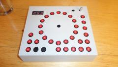
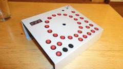
From the album: nebula-circle seq
Here's another 3/4 view with no flash ... -
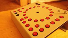
From the album: nebula-circle seq
The case still needs to be marked up and legended -
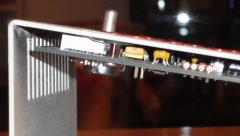
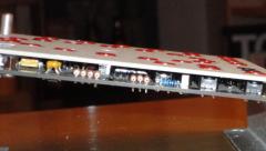
From the album: nebula-circle seq
Another panel side view. -
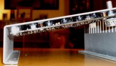
From the album: nebula-circle seq
This shows the amazing J-B Weld technique I learned from building the MB-6582. Click to zoom in for a better view. Thanks, Wilba. -
From the album: nebula-circle seq
This pic shows the height of the buttons pretty well. It was hard initially to find 5.8 mm spacers, but I'm really happy with the result. And despite an incredibly tough time finding the spacers online, a local surplus electronics shop happens to have thousands in stock! -
From the album: nebula-circle seq
The case is a Hammond 1456FE1. We are only seeing the top portion of the assembly. All those holes are drilled, and I used a Dremel to get the square hole for the BPM display. I will be putting a tinted diffuser in there... -
:thumbsup: nice
-
For a one-off personal design, the "classical way" is the way to go. The software is already written this way, and there really isn't a big savings in ICs. Here he's using 4 SR's - yes you could matrix it down to 2 SR's, but then you've gotta stick in 32 diodes and modify some code. AFAIK all the MIDIbox projects have the resistor to VCC ("pull up resistor"), but can be easily changed to the opposite logic. Check out the DIN schems on ucapps.de.
-
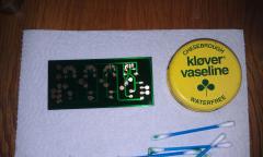
JB-Welding the Circle Sequencer front panel, attempt #1: fail.
-
There are extra rows on the DIN modules so you can use SIP resistor networks or discrete resistors as pull-ups. There are drawings on SmashTV's site that illustrate this. There is no advantage to using one over the other. The 100 uF capacitor is a fairly recent addition. It's C5 in this schematic. I have made several MIDIbox projects with DOUTs and I have never used or needed this capacitor. You might, if your project uses a lot of high-current LEDs, or motors, or if it has a shitty power supply, or perhaps other reasons. Others may disagree with me, but I would leave it out unless I needed it for some reason, especially since you'd probably have to solder it to the bottom of the board.
-
I've been down this road. You can find the Pioneer parts a bit cheaper on eBay. But you will not find these parts available through any regular vendor like Mouser, Digikey etc. But the quality of the Pioneer stuff is exceptional.
-
 I really like the look of this. What is the name of the soldermask product? There aren't a lot of spray soldermasks on the market here. Thanks
 -
I'm a bit pissed off that I received some IC sockets from Newark that look like these on line: http://canada.newark.com/fci/dilb8p-223tlf/dip-socket-8pos-through-hole/dp/53K0893?Ntt=53k0893 http://canada.newark.com/fci/dilb14p-223tlf/dip-socket-14pos-through-hole/dp/53K0888?Ntt=53k0888 I just got them today, and they're not as pictured. If you look at the datasheet links on those pages, you'll see that they're not the nice sockets with the circular machined holes ... instead I got cheap, dual-wipe sockets. Caveat emptor, I suppose. :mad: I bought quite a few of them for my 9090. I really wanted the boards to look nice, and I do prefer the machined sockets if you think you might actually be changing the ICs around a fair bit. The problem is that they're always so expensive! Does anybody know of a decent line of machined IC sockets that I can buy 50 of without having to mortgage my house?
-
Still building my 9090 ... just installed R420. Must be time for a break!
-
Maximum is 128 DIN inputs. DINX4 has 32 inputs, so you can use up to 4 of them. http://ucapps.de/mbhp_din.html
-
A quick thought: double-check how close to the jack you can put the headers. The jack's housing may obstruct whatever receptacle you try to connect to the header.
-
No major manipulation is required. Encoders and buttons can share the same DIN ICs. The only rule is that encoders must be on one of the 4 primary input pairs on a DIN IC (so 0+1, 2+3, 4+5, or 6+7 - you can't do 1+2 for example). You'll get this when you configure your first app. Your parts list makes sense, but you should double-check the musings on these forums about DOG LCDs. I don't know how well they perform under MIOS8, and they don't work with all apps. You might be better off going with a "regular" HD44780-based LCD. Try Farnell? Or maybe digi-key? You'd be better served just ordering the boards from either of the two web shops that offer them for sale. Smash TV: http://avishowtech.com/mbhp Mike: http://www.mikes-elektronikseite.de/mshop_englisch/ Either that or try making them yourself - it's not that hard, and single-sided layouts for all these boards exist.
-
Did you wait until 8:08 to post this? Weeeeeeeird Dude I would so totally take you up on this if I could afford it right now.
-
WOW! From Germany, Sept. 5, to Canada, Sept. 13. Very nice. My Logic Controls will finally get their own MIDI interface. Thanks TK!
-
Audio out preference (RCA, 1/4", Mono, Stereo)?
nebula replied to m00dawg's topic in Design Concepts
Yup! If it's mono, ground the ring and sleeve together. Or use a mono connector with no ring. -
Sounds good to me! Don't forget to bring your partially completed PCB, spare components, tools, and consumables like solder and flux on your carry-on for testing and debugging. Airlines love that kind of stuff.
-
I am curious: are these boards white?
