nebula
-
Posts
943 -
Joined
-
Last visited
-
Days Won
4
Content Type
Profiles
Forums
Blogs
Gallery
Everything posted by nebula
-
Doug posted about it today at http://electro-music.com/forum/viewtopic.php?p=353389#353389 Hopefully nobody will mind if I re-post it here. Apparently he has plans to produce a 9090-like set of two boards with 808 voices once he ships the MB-808 kits...
-
Midibox and 9090 Drum Individual Accent... is there a Way to realise this
nebula replied to jamie's topic in MIDIbox SEQ
Thorsten, this sounds excellent. I have a couple of comments / suggestions, sincerely intended as constructive input ... (1) Do you really need all 8 pins of a DOUT for drum machine dynamics? The TR-909 sequencer only offers two dynamic levels per step (not for all sounds though). Even if you use 4 pins, that could still allow 16 levels per sound and you could use a single DOUT IC for two voices' dynamics. (2) How do you plan to add such a great deal of velocity control to the MIDIbox 808 UI? The TR-909's two dynamic levels are cycled through as you press each step ("GP") button. (3) I haven't looked in great detail at the 9090 schematic, but I believe it somehow uses the only a single resistor array to achieve full dynamics for all drum voices. (4) Finally, I wonder if MIDIbox 808 is still a good name for this project, for a couple of reasons. The MB-808 is a TR-808 clone, of sorts, and a MIDIbox-based drum sequencer powers it. The sequencer is similar to the TR-606, and soon also the TR-909/TR-707, but it expands on those sequencers with numerous really cool, modern features. The name "MIDIbox 808" leads newbies to believe that the ucapps project is an 808 clone, when in fact it is much less (no sounds) and also much more (more comprehensive sequencer). Maybe something like "MIDIbox0x" or "MIDIbox beatbox" or "MIDIbox drumSEQ" describes what you're doing without suggesting that it strictly clones the 808, and also distances this multipurpose sequencer from the MB-808 project. -
I've been quiet lately, but I'm still in!
-
Don't forget bankstick for storage. For that you'll probably just want to put a few EEPROMs on a piece of perfboard. You'll find the bankstick schematic on the ucapps.de page. There is no pre-designed front panel available as far as I know - especially since it will depend on the buttons you use. Welcome - and good luck!
-
 This is pretty cool! Is the layout or board available?
 -
I would love to have a hardware audio input that goes to a comparator, then to a DIN. Pressing a button on the MBCV would cause it to measure the frequency on the DIN and calibrate a voltage look-up table so that it can play perfect scales, regardless of the oscillator's response or temperature. This is similar to the auto-tuning in many vintage analog polysynths, and these days it's a very compelling reason to use something like Silent Way or Volta instead of a dedicated MIDI>CV converter.
-
Smash, how much longer?? I really need mine for a school project :frantics: :frantics: :frantics: :frantics: :frantics: :frantics: :frantics: :frantics:
-
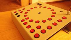
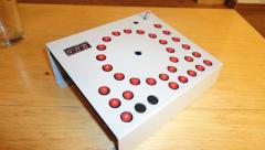
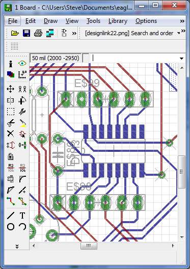
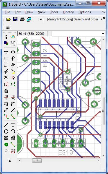
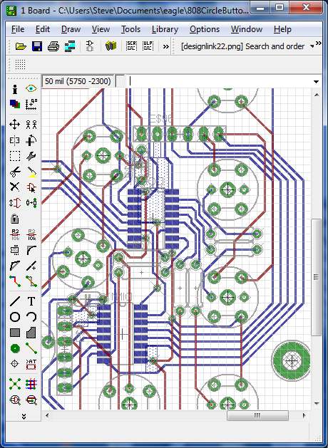
For my circle sequencer project I had sketched out the panel first using the drawing tools in MS Word. Then I designed the board using Eagle. When I created the footprint for the pushbuttons, I added an extra 1/16" hole right in the middle of the component: I then clamped the unpopulated circuit board to the back of the panel and drilled through each hole with a 1/16" bit. I removed the panel, then enlarged each hole using a stepped drill bit. I know this isn't exactly what you're talking about, since this is a homebrew panel, but ... for this project I used the board as a stencil to cut the panel.
-
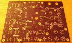
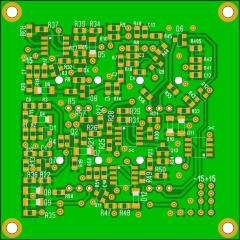
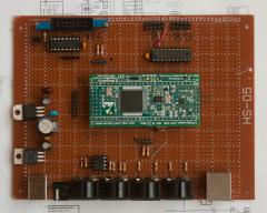
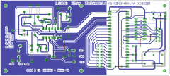 Heehee there's not a lot of work that went into it. Just flipped the mixer upside down so that it would be easy to connect to the AY. Yes the PCB could be much smaller, but I don't need smaller ... this will be my own home etch job, which tends to be a little imperfect, so nice and big means nice and easy to troubleshoot. As a Canadian, instead of "MIDIbox AY" I might have to call this project "MIDIbox, eh?"
 -
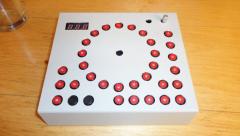
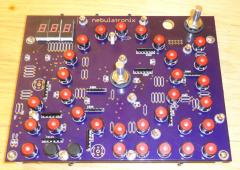
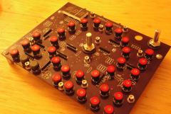
My MIDIbox 808 "Circle Sequencer" ... pics from all design phases
-
-
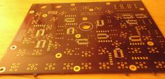
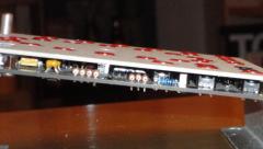
From the album: nebula-circle seq
MIDIbox AY board layout for AY-3-8910 directly connected to op amp mixer -
UHM! AHEM!! COUGH COUGH COUGH -nerd- COUGH! /me thinks he'll delete his name and add it to the end, giving Hawkeye board number 75 just for being such a dork.
-
Good find, sneakthief! I stand corrected - although I see Mouser lists them as a new product :) Did the faders fit? Are they the same quality as the originals?
-
n/m
-
If you're only seeing continuity with the polarity one way, you're likely just seeing the bridge rectifier. I suspect there's nothing wrong. I admit I still haven't finished my sammichSID, but of all the projects I've ever built - MIDIbox and otherwise - I don't recall ever checking continuity between gnd and +V after the components are loaded. If you're seeing voltage when the power supply is connected, and no smoke, there can't very well be a short! Have a nice trip...
-
16-channel MIDI controller with motorised faders for DAW
nebula replied to zztop's topic in MIDIbox User Projects
The MIDIbox LC ("Logic Control") project uses the "MF" module ("Motor Faders".) A revised "MF" concept has been developed. It is an improved way of working with motorized faders. If I were to build a MIDIbox LC I'd probably go bleeding edge and make it the newer way. Refer to this thread: -
So ... does this mean that if you get the black knob as you pictured on the left, there is no pointer on the knob itself ... meaning that the orientation is irrelevant, since the pointer is only on the cap? I'd probably get a bunch like that too, since I'm considering new knobs for my MS2000, and they'd work well on the MB-808 too.
-
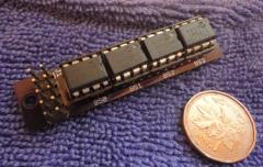
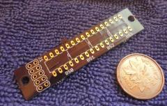
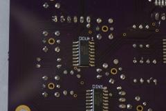
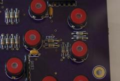
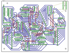
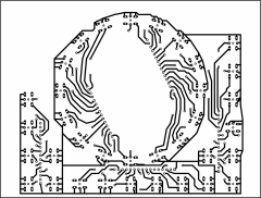
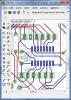
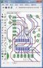
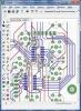
For my sequencer project I'm using SOIC shift registers, and 5-resistor (6-pin) thru-hole SIP networks as pullups. (Also I used thru-hole bypass caps). On one side of the SR there is an unused resistor in the network, and on the other the 5th resistor is used as the pull-up on the SR chain signal. I found myself occasionally connecting both the pull-up and the button input directly to the IC pin - the order will make no difference. I chose the bussed thru-hole resistor networks mainly because they're really cheap. I don't know if it's any help or not, but I'm attaching a couple of pics that sort of illustrate how I did it... at the very least it may give you some ideas. I think you can click the thumbnails to make bigger images The first pic shows a basic DIN SR with pull-ups right by the IC. The second shows a DIN SR where I didn't have room for the pull-ups. This was the last DIN in my chain, so not all pins are used. The third shows a DIN SR where there were other components and traces in my way, so I had to move the resistor network to another part of the world.
-
 Lookin good! Did you test it?
 -
If you're seeing voltage while the board is powered, but then you remove the power and you get continuity at the same point, then your continuity-testing instrument must be getting tricked by a load. Try measuring resistance (in ohms) instead of simply measuring continuity. A short should appear as < 1 ohm. Also, make sure your transformer is not plugged in to the board (even if it is unplugged from the wall) when you are making these measurements. If you're still seeing a short, maybe check the orientation of the bridge rectifier?
-
I don't know about the "build email" you're referring to, but sammichSID Build Guide 1.0 (the latest) is available at http://www.midibox.org/dokuwiki/doku.php?id=sammichSID#sammichSID_build_guide You need a regulated 12V external power supply for sammichSID. Maybe you read the paragraph on page 17 of the build guide that says the 6582 SIDs require 9V? This is true about the SIDs themselves, but not the external power supply. Read page 17 from the top. Plug in a nice 12VDC supply, place the jumpers correctly and you should see 9V on the SID sockets. To answer your last question, malfunctioning regulators can be rather unpredictable. Sometimes they allow overvoltage, sometimes the voltage comes out low, sometimes they open, sometimes they oscillate. As an aside: I read your post several times, confused, because "VR" to me means "Variable Resistor". I recommend you just use the term "regulator". Good luck, and welcome to the forum!
-
Learning, through trial and error, the art of finishing wood.
-
Usually it's the 5V part that goes. Maybe you have a bad connection or an intermittent cord. Or you may have shorted and burned out the 9VAC part. In some parts of the world, the C64 power supply can be taken apart. Here in North America, they can't. There are numerous discussions here about brewing your own C64 power supply. It might be helpful if individuals who have built one could consider creating Wiki pages to document their creations. I still plan to make a C64 power supply myself, as I have blown up about 3 of them in the past few years. I have already bought all the components. I still need an enclosure, and I *do* plan to re-use the cable with the DIN plug from one of the defective power supplies.
-
I presently need about 100-150 pointer knobs for some analog drums I'm working on. I am also on the list for a Rev 3 MB-808 board, so I will need knobs for that. I am not terribly fussy, but I always liked these ones, and I used them on my x0xb0x: Here's what I NEED: 6mm D-shaft (is that a "given"?) slim Here's what I like: soft-touch Here's a question: Is it ever OK to interchange 6 mm and 1/4 inch d-shaft knobs? (1/4 inch is 6.35 mm)
-
 Thanks Hawk! Getting the right button height took hours of measurements and calculations... the spacers had to be between 5.5 and 5.8 mm. If the spacers were any bigger, the buttons would be flush with the panel, and if they were any smaller, the BPM display would not leave room for a lens. Greets back, Steve