

nILS
-
Posts
4,314 -
Joined
-
Last visited
-
Days Won
4
Content Type
Profiles
Forums
Blogs
Gallery
Everything posted by nILS
-
 Insanity... :)
 -
R80
-
Wilba totally comes crying to me everytime someone doesn't go with the mb6582 option and actually does real DIY ;) Then I have to :console: and give him some :flowers: and he's good again! Seriously though - tipping hat good, making a new never-before seen case good, too!
-
Seems to work here: http://nic-nac-project.org/~rocket/midi/vmidibox/dev/
-
"Take off shirt while wiring this part" - yes, defo audiophile :thumbsup:
-
Thanks!
-
Love you, too :flowers:
-
Offsite doco disappears. Period. That's why it's a "requirement" to have doco for user projects here on site - attached to forum posts or on the WIKI. See Please Read Before Posting New Topics: What is a "User Project"?
-
Can I Build My own combined MIDI merge and thru box.
nILS replied to pj-27's topic in Design Concepts
Welcome aboard pj-27 :flowers: Please read the stickies. Especially Topic moved. -
Yep, I've been using that as well :)
-
How to port mios32 to other microcontroller?
nILS replied to Arkadiuz's topic in MIOS programming (C)
Welcome aboard Arkaduiz :flowers: That's a fairly "deep" question and answers sometimes take longer than 24 hours around here... Sadly we're not getting paid to do this ;) I think you might want to start by having a look at the mios32 repository at http://svnmios.midibox.org/listing.php?repname=svn.mios32&path=/&. That way you might get a rough overview over what is there, and how much is there. It would also be helpful for us to know what exactly you plan to do. -
With some extra coding it is well possible, yes. I am werking on sth. similar but a bit more advanced for the core32 at the moment. A few ADSR EGs are certainly doable within the limits of the pic.
-
Müsst ich mal schauen, ich denke schon, dass ich einen gm5 + die kleene Platine (oder eben gleich eine anständige gm5x5x5) übrig hab.
-
MIDIbox of the Week (MIDIbox CV of Altitude)
nILS replied to Altitude's topic in MIDIbox of the Week
Nice box, Altitude, good to have you back! :flowers: -
War eine Schätzung, aber wie dem auch sei - was hast Du denn für ein Problem damit? Chip 4,50, PCB 3,00, dann noch ein paar Widerstände und anderer Kleinkram.
-
Yes.
-
Bester Tip: gm5. Mal hier im Forum suchen. Das vermutlich beste MIDI Interface wo gibt für unter 15eur ;)
-
I approve :flowers: Wilba doesn't like being hugged by guys though... :whistle:
-
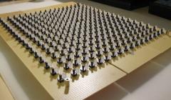
Well... I see (among other things) 9 * 4 = 36 LEDs. With the default 220 Ohm resistors you're looking at roughly 15mA per LED. 36 * 15 = 540mA. To bring the total current consumption of the the LEDs to a reasonable level of say 72mA you'd need 1.5k resistors, which will dim the LEDs to the point of them barely being visible (if they work at all @ 2mA)...
-
That's what J2 is there for (among other things). It's generally advised to remove the voltage regularot and bridge pins 1 and 3 (in and out) if you do that. Then again - don't do it. USB is really not meant to power stuff with a current draw >100mA. The thing with the Y-cables is that you need to connect it to two different ports on the PC side. Not just two usb sockets, but two individual ports. The USB ports on a lot of mainboards are all connected to a hub internally so they may just be the same port - with a total of ~100mA to be used.
-
The 1.4V you got are easily explained - You're feeding 5V DC into the bridge rectifier of the core module - diodes cause a voltage drop - then the voltage <5V goes into the 7805 which needs ~7-10V to work properly. What you are doing can't work. J2 can be used to supply power to a core module (if you know the voltage is constantly really nice 5V, polarity is right etc.) that's really all that bad at all - if you know what you're doing (the "no J2" comment makes me kinda doubt that a little bit :whistle: ). But I do agree that powering the core via J2 from USB power from a gm5 is bad juju :) With a gm5 and a core + some peripheral (there's going to be more than just the core, right?) you'll easily get over the max. current a USB port can deliver. And that can do anything from simply not work to blow up your maiboard. -
-
Hehe, sometimes it helps talking about a problem... :thumbsup:
-
hehe, whoopsie :) Typo DINx1/4 -> DOUTx1/4, fixed original post, thx lyle!
-
Pots vs. encoders: http://midibox.org/dokuwiki/doku.php?id=questions_and_answers * You'd prolly want an extra encoder and some buttons for the display (to allow quick and easy menuing)
-
* Do you want potentiometers or encoders? * You do want the display. It's really nice to have a display for debugging purposes, and generally helpful after debugging. * 20 buttons -> 1 DINx4 module * 17 + 4 = 21 analog inputs -> 1 AINx4 module * 8 digital outputs -> 1 DOUTx1 module (get a DOUTx4 for expandability) * You also need a power supply More LEDs are generally nice for more visual feedback, too. Throw together a mockup of the panel, that'll help us find possible problems a lot easier :) edit: fixed DIN/DOUT typo mixup