julienvoirin
-
Posts
790 -
Joined
-
Last visited
-
Days Won
3
Content Type
Profiles
Forums
Blogs
Gallery
Everything posted by julienvoirin
-

Simple Balanced Audio Circuits Possible with MB-6582?
julienvoirin replied to m00dawg's topic in Design Concepts
only transformers for passive (lundhal, jensen, etc) line driver for active e.g http://www.ti.com/product/drv135 the best is to use a DI -
i can sell u a 3U rack case, exactly the same as i used for my seq, as it is spare. it comes from selectronic and is no more manufactured. it fits Wilba's PCB+ Panel (need to cut the edge)
-
:thumbsup: :thumbsup: :thumbsup: :thumbsup: :thumbsup:
-
i do not use the midi out of Matrix (no handshake). i only plug the i2c out to their midi in the only one time you will get midi data from Matrix is when you will save its presets in the bankstick ultracore uses its core midi in (receive midi notes, program change, CC, clock and forward them to I2C) and core midi out (program change, clock ...) yep, check Matrix 6 user manual
-
hi xaro the easiest is to get : an Ultracore (as you will need 8 bankstick and I2C) one DINx4 module from smash tv one DOUTx4 " 4 analog multiplexer CD4051 (as you will solder them on the control surface containing pots ans switches) Things are connected as in midibox64. Unused analog inputs are clamped to ground. Then din, dout and pots are defined in the application : din.c & din.h pots.c and pots.h numbers refer to http://svnmios.midibox.org/filedetails.php?repname=svn.mios&path=%2Ftrunk%2Fdoc%2Fmios%2Fmios_din_dout_pin_numbers.txt din.c: Has to be filled in (DIN_ConfigMap[32]) The dins need to be listed in order that correspond to their pin number in the array. And of course each entry must point to the the DOUT pin for its corresponding LED. din.h has a few of the pins in din.c #defined to improve code readability wherever its used. So make sure anything in din.h that starts off with #define DIN_ or #define DOUT_ pots.c: Rearrange the entries in PotConfigMap[] to correspond to their pin positions. Then edit the #define POT_OSC1_***, POT_FILTER***, etc. in pots.h to match their config in pots.c i followed jackchaos design, i only defined different pin numbers in order to simplify my building (shorter wires and copper). i also add some more buttons ans leds to enhance functions. have a look and come back if needed. Cheers
-
I got that too !! with a fuse under. salvaged from the VTR
-
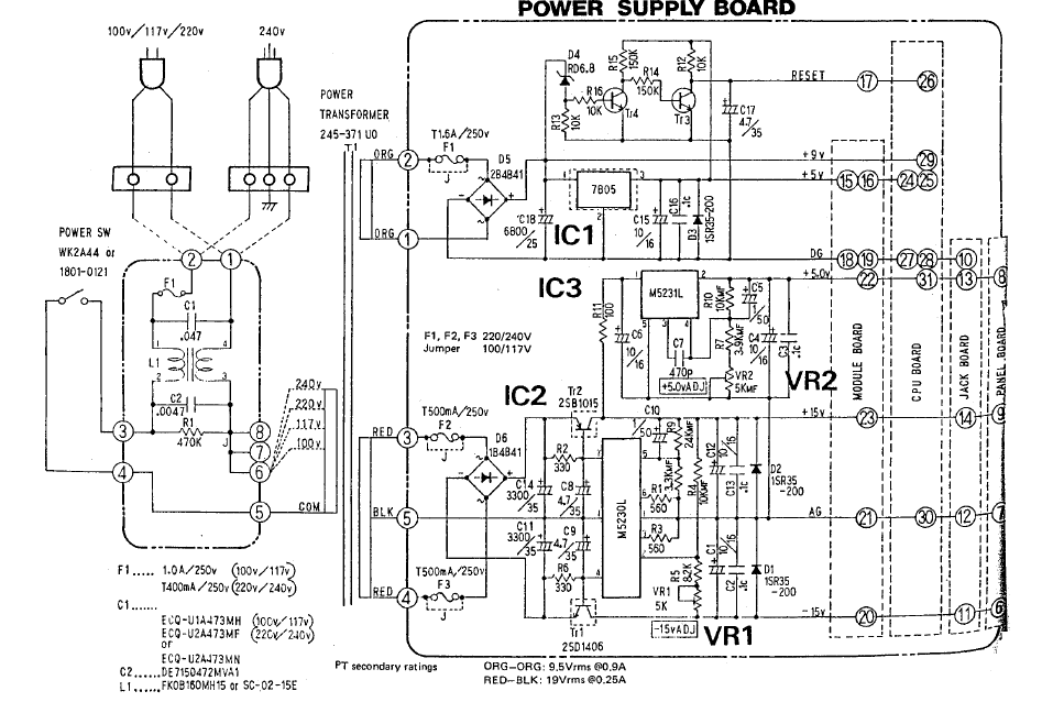
that's a great job to have produced a so clean schem, especially for beginners me too, a long time ago for general purpose then integrated to my MB CV (+12/-12V analog, 5V digital). So i need to do another one (based on variable VR) It works perfectly. it has the quite same schematic BUT : - i didn't used D1 D2 D3 D4 as there are LED that do the same : abort negative pulse in case or short circuits or similar, showing that a voltage is present (and doing a load by the same occasion in order to mesure the exact voltage) - I used only 2 caps of 1000u (+ one 2200 on the core) before the VRs, the rest being 10u, 330n and 100n. Long observation with an oscilloscope showed perfect linear voltages. Connecting DGnd and AGnd will create ground loop in the final circuit with Core and AOUT_NG Making it on veroboard goes very fast, the longest is to drill additional fixing holes for the transformer ; moreover this permits to adjust the size of the 2200u capa as you know that depending of the voltage, legs space is different. The necessity to adjust the voltage of capa is important as the cheapest is to recycle an old transformer from a VTR for example. I restored last days a Juno 106. You should copy its powersupply and then do a batch : there are 5V in analog and digital, +15/-15 in analog, and a 9V line (what for ??). there are trimmer to adjust voltages. It has fuses (5 in total!) that saved my life and my VCF/VCA circuits while i was experimenting into. There is also a retrocontrol circuit into (as on Switch PSU) but with a transformer ! So cool :) in french : http://www.sonelec-musique.com/electronique_bases_alimentations.html
-
according to pic : switch PSU linear psu, so the price the best is to make your own in this case. recycling the transformer of an old VTR is a good option, maybe using the existing circuits. whatsoever : http://www.midibox.org/dokuwiki/doku.php?id=bipolar_12v_psu
-
-
yes i know. I can't find back its box, but the brand is ELGA. parisian people can maybe find some in Selectronic Nation, in their backstock (maybe 2 or 3 units left) a good trick is to cut the power plug with a dremel in order to access the 220V wires. then you fix it in the rack enclosure with screws in the 4 corners. It is molded and a pain in the ass to open
-
tested and approved in Seq V4 http://www.selectronic.fr/article.asp?article_ref_entier=11.4418-9999
-
very nice, really is this sticker or lexan or what ?? quality is amazing
-
500€ and 2 weeks (soldering is fast) machining is long (JB Weld takes 3 days minimum considering drying time)
-
Hi guys I've recently switched to Logic pro (i am coming from Protools for editing audio tracks - i work in broadcast) and this is really a very powerful DAW ! I discovered that there is a stuff called Environment, which allow to create complete channel strip and even complete mixer setup, including bus routing and so on ... in audio and MIDI ! So what I am looking for are some .lso or sessions in order to understand how to start with good templates, as i am currently starting from virgin session but this is rather annoying and long to setup. Some tutorials based on a complete project (from beginning to the end) are very welcome, as long as some producer tips regarding sidechain, gating, phasing, management or the mixer, etc .. I am equiped with a Mackie Control clone (M Audio ProjectMix), several hardware synths (Juno, Oberheim, Moog, SID), Drums machines (electribe, machinedrum and MPC) and a hardware reverb. Computer is Powermac G5. Thanks in advance for all your tips (i've already seen Future music videos, logic cafe website, and some random youtube stuff, very well explained)
-
 :thumbsup: :thumbsup: :thumbsup: :thumbsup: :thumbsup:
 -
the best would be to connect four DINx4 directly to key's contacts and remove the resistors ; why ? for polyphony ! then use ain64_dout128_din128 default app ///////////////////////////////////////////////////////////////////////////// // This function is called by MIOS when an button has been toggled // pin_value is 1 when button released, and 0 when button pressed ///////////////////////////////////////////////////////////////////////////// void DIN_NotifyToggle(unsigned char pin, unsigned char pin_value) __wparam { // a button has been pressed, send Note at channel 1 MIOS_MIDI_BeginStream(); MIOS_MIDI_TxBufferPut(0x90); // Note at channel 1 MIOS_MIDI_TxBufferPut(pin + [size="4"]OCTAVE[/size]); // pin number corresponds to note number MIOS_MIDI_TxBufferPut(pin_value ? 0x00 : 0x7f); // buttons are high-active MIOS_MIDI_EndStream(); // notify display handler in DISPLAY_Tick() that DIN value has changed last_din_pin = pin; app_flags.DISPLAY_UPDATE_REQ = 1; } where OCTAVE is the transpose trick on a smaller than 128 keyboard
-
SammichSID voltage tests - reading 12.3V
julienvoirin replied to Rude Mechanical's topic in Testing/Troubleshooting
http://uCApps.de/mios/mbsid_testtone_v3c.zip mios8 download section -
SammichSID voltage tests - reading 12.3V
julienvoirin replied to Rude Mechanical's topic in Testing/Troubleshooting
moreover there is a test_tone app to test (ahaha) that the SIDs are OK and the circuit too : it output a 1KHz signal (square wave ?) -
snif :bye: i wanted it ... but was too busy to answer
-
I want to learn programming. Where do I start?
julienvoirin replied to JRock's topic in MIOS programming (C)
+1 exemple mios8 section on the website is good too http://www.ucapps.de/mios8_c.html PS : arduino comes after as there is only C++ tons of codes or only pseudo C code (no .h ) -
In my opinion --> no :( there is a trick to bypass this problem : include simple DIL connectors on the back of your Control Surface PCB (repense au cable nappe IDE), then connected with flat cables to a "patch" PCB, then connected to regular DIN/DOUT advantages : -this way you limit the risk of errors as you work on 3 small PCB instead of a big one, -you can do cross patching if you made mistakes in your eagle routing, as you just have to remake a flat cable between ''patch PCB" and DOUT/DIN modules. This limited the spaghetti stuff too !. This as been used on Arduinome project (arduinome shield with sparkfun buttons cons : not ultra clean like a wilba seq :/ you can call me if you want me to explain how i imagine the stuff best regard PS : if you aren't confident with eagle, i advise you to build on veroboard. i did this with 16 encoders, including the DINx4 on the back, using coloured flat wires : cheap, fast, easy, rather clean
-
Looking for potentiometers like on dj mixer eq knobs
julienvoirin replied to hydre's topic in Parts Questions
the best is to get some samples, then choose -
imo this won't be easy as there should be lots of tracks, especially for leds (regarding your front panel design) the trick is the backside (think to resistors ...) like in monome, or sandwich (Wilba) sharing your pcb routing would give answers nebula designed a CS based on CMS ; don't be afraid about cms, they are rather easy to solder when you know the trick (adding some flux before soldering ; desoldering is another story)
-
i'll be happy to help you (despite my few free time), i did not imagine you were so advanced in the project :thumbsup: concerning your PCB, i really advise you to integrate shift registers (74HC595 and 165) in the design, on the backside for example, even in CMS (SMD). Another solution to bypass goldphoenix size is to create 2 PCBs (10U !) linked by a cable like those in scsi (50 contacts) or IDE Hardrives
-
FM is really nice :thumbsup: