Imp
-
Posts
419 -
Joined
-
Last visited
-
Days Won
4
Content Type
Profiles
Forums
Blogs
Gallery
Everything posted by Imp
-
What a nice exhibition of skill and taste! :thumbsup:
-
As m00dawg said, running the editor and a DAW in parallel doesn't work. What you can do is map the editor and your DAW to different virtual midiports (e.g. MidiYoke) and use Midi-OX(or -trix) to merge those ports.
-
It has an option to defragment midi-data, which could solve your problem.
-
First thing i'd try is using another OS, if you have the option. I don't know if your problem could be caused by fragmentation of the midi-data, but you could try using miditrix. Are you running a DAW in parallel? Maybe it sets the cutoff to zero, everytime you play a note? If your problem doesn't occur with the filter switched off (on the sammich), this might be the case.
-
16 encoders? I once knew a website where people were building midicontrollers all the time...I wish i could remember it's name :tongue: maybe put a 64e into a cheap midi-keyboard?
-
Hehe, you mixed me up with the threadstarter, didn't you?
-
No, it just turns on, when you select one of those positive waves...or at least it should ;) Without it, you can still see if you selected a positive wave, because then two of the LFO-Waveform-LEDs will be lit. Have you checked, if the used SR/pin isn't already in use by another function?
-
Sorry, i didn't know this was different on a sammich...
-
I started with a "mixed pair" but soon felt the need to change that. It works, but matched is the way to go, IMHO...
-
When do you expect it to turn on? Maybe you got that wrong? ;) In the LFO menu you have to set the Waveform to PSn,PTr,PSw or PPl... If this isn't the problem, i don't know what else to check. Maybe someone with a working LFO+LED can chime in?
-
Are you sure, the LED works? You can use a battery with a resistor in series to test it in the circuit, but if you can, you should disconnect it from the Dout first. Did you add DOUT_ENTRY TMP5, 5, x, y ; LFO Positive LED below "CS_MENU_DOUT_TABLE" in setup*.asm? ( with x=number of shiftregister and y=pin, e.g. 6,3)
-
Hi, have a look at the page about the core. There you can see, that the core needs 5v, but has a rectifier and a linear 5V-regulator on board. It should be supplied with 7-10V AC. You can use gnd and +15V, but if you use a LCD with backlight, the regulator will get hot.
-
Hi, how did you get -12V for the Aout_LCs out of the C64-PSU? Either your encoders are quite bouncy, or there is something wrong on your DINs. I'd check the dins for soldering errors first. Have you tried changing the encodermode?
-
Your D0-D3 issue sounds familiar. I think the reason for this behavior is that the interconnection test was written for pic18f452, which handles the LCD pins differently, but don't take my word on it. Try switching between 4bit/8bit mode (via pic-header), to make the LCD work in mbfm too. Your attempt to save toner was a nice idea, but what about the wasted etchant? :tongue: I can't say if this damaged anything, but i guess it would kill the Yacs first. Maybe the oscillator got a little too much voltage bedause of the wrong ground. If you have a multimeter that can measure frequency, check if the osc still does its job.
-
Hi PJ, as far as i know, all versions of the C64-psu had the same pinout. So, pin 6 is located as shown in that picture. It doesn't matter, if you exchange pins 6 and 7, because the AC they deliver gets rectified afterwards. You can see that in the pdf: those diodes marked "X1" are the same for both lines. To identify pin 5, just use a multimeter.
-
I mek corekshun for u: he delishus!
-
Achso, na das ist natürlich genau richtig.
-
Das ist eigentlich ziemlich egal, ich persönlich lasse den Lötkolben immer so wie er ist... Ab und an putze ich die Spitze im heißen Zustand mit nem nassen Schwamm ab. Um ein Netzkabel zu flicken würde ich eher Lüsterklemmen nehmen als löten, wobei das aber auch nicht so ganz das wahre ist..
-
Your drawing is almost the setup ssp described. The only difference is, that he uses a usb-to-midi interface with multiple ins/outs which is inside the mixer. This interface is called gm5 and if you build this instead of using the cables+hub, you will avoid lots of trouble. These cables, and even more expensive interfaces too, they tend to lose data while uploading apps. ATM it's easier to stick with the core8, because the apps are already written for it, but haven't been ported to the core32 yet. You'll probably only need one bankstick, unless you want to save lots of configurations, which doesn't make sense ;)
-
Newbie wanna build a "analog console" midi controller
Imp replied to Jadestar's topic in Tips & Tricks
Also, at first you don't have to understand every detail. You only need a general understanding of what can be done. How to do it exactly, is hard to answer, if you don't know what you want to build. So, get a rough overview, then decide what to build. Your "audio mixer"-idea is, as philetaylor said, possible but not for beginners. If you want a midicontroller with faders instead, have a look at MidiBox64. It is quite simple and could be upgraded to a MidiBox LC later. -
Burnt pcb holes trying to replace encoder
Imp replied to Echopraxia's topic in Testing/Troubleshooting
They look the same to me. If you haven't assembled them yet, you could check if those contacts inside are connected to the same pins on both encoders. The schem confirms: The pin, i marked yellow in the pic must go to ground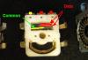
-
Burnt pcb holes trying to replace encoder
Imp replied to Echopraxia's topic in Testing/Troubleshooting
POIDH! :whistle: The traces :rolleyes: Or maybe you accidently connected the datalines to ground... Could you also take a picture of the pcb, which shows the whole area around the encoder? I will mark points on it, to check for continuity, if you do... -
Blue LEDs emit lots of energy within a small bandwith, so when you realize they are slightly too bright, they might already damage your eyes. Just connect one LED with it's resistor+ a pot, and tweak until you like it. Then measure the combined resistance and replace all resistors accordingly. But keep in mind, that usually you'll have like 20 LEDs lit at once :wink: edit: dammit, too slow ;)
-
Burnt pcb holes trying to replace encoder
Imp replied to Echopraxia's topic in Testing/Troubleshooting
It looks like right pin is the ground/common pin and middle and left are the data lines, which are pulled up via those resistors. May I suggest you try to pry open the old and new encoders to check their pinouts?