latigid on
-
Posts
2,524 -
Joined
-
Last visited
-
Days Won
149
Content Type
Profiles
Forums
Blogs
Gallery
Everything posted by latigid on
-
Are the LCDs powered by 3V or 5V? How hot is it where you are? Without much more info, the problem could come down to the DISCO board voltage regulator overheating. Is the USB cable okay? Maybe the connection doesn't make good contact somehow.
-
What kind of PSU are you using? Does it supply enough current? Can you measure (or better 'scope) the power rails? Photos of the connectors could help.
-
LEDs are nice and bright; this is from the rear side! I'll need some help/fiddling with the switch portion as this is not a 1:1 BLM. I noticed a similar concept from 40%club: http://www.40percent.club/2017/06/alps-48-rgb.html I considered mounting 5050 LEDs in this way last year, but IMO the available ones are not really bright enough. As well, I'm not sure how reliable a "bridge-soldered" LED would be in the long run after a lot of keypresses.
-
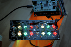
From the album: Mech SEQ
© 2017 latigid on
-
It should work, although I'm not sure of the advantage over my concept with illuminated Matias switches. Don't take it as discouragement; this is MIDIbox and you are free to design your own hardware as the original spirit intends. Best of luck, Andy
-
A little while ago I found my collection of mp3s I made with my band about 10 years ago. Everything is LoFi with distortion and dropouts as the jams were recorded onto a dynamic mic and then cassette tape, then transferred to the computer. No processing in post, mistakes not fixed, no song titles, just the code of the tape and a few descriptors. The mixes are often off, and these were just recorded as they come, so can be quite long-winded. But I still find them quite cool. Synths/keys used are Moog Voyager, Rhodes '73, Rhodes Chroma, a couple with MS-20. Sherman Filterbank, RE-150 Space Echo and Moogerfooger effects. I play bass on a couple. You'll probably like the "jungle" drum and bass drums (all live), and there's some vocals too. The singer probably prefers that his levels are low :). Can't be bothered with Soundcloud/youtube at the moment, so I'll post links to dropbox. https://www.dropbox.com/s/gtfo0yzb86lr7wq/65A%20distorted%20fedback%20db.mp3?dl=0 I think the delay used here is a Boss DM-300, a 4096 cell BBD. The input is overdriving which gives some very crunchy sounds on the Rhodes. If anyone likes, I can post the longer ones which go up to +20 minutes continuous. Mostly it's dub/drum'n'bass style but there are some different ones too. Best, Andy
-
For those playing at home, there's a delay on Matias switches, apparently as they are producing a newer design with "reduced key wobble." I didn't think the wobble was too bad, but there you go. The restock is due at the end of August. In the meantime I will try to test things without switches and also look at an order of keycaps.
-
Nice! Analogue detuning from the Dom ?
-
 Should be okay. With a matrix design, you usually get entire rows or columns out rather than a few here and there. One thing I've noticed, is that the through hole plating is not always the best. For LEDs and switches that don't work, try soldering on both sides of the joint, adding flux if you need to. You have to be careful of melting any plastic components, and also e.g. soldering LED legs one at a time so the alignment stays good.
 -
Ah, it's the MB-6582 one I suppose. Can help there then.
-
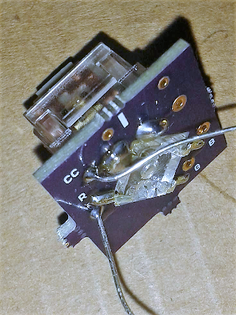
Is it the one for the Quad I2C MIDI? The pin arrangement is special, having "3-2-3" rather than the much more common "1-4-3". I can have a look in the parts drawers. Best, Andy
-
Looks like a nice wheel! Compare with the DK-38: http://www.albs.de/ecom/images/866004.pdf The RS one is just 1mm shorter in total height, so I'm not sure if that would make too big a difference.
-
The idea uses a DK-38 knob from ALBS, and I've asked Adrian to accommodate for it by cutting a hole in the front panel. So it will already be sunken down a bit. But no, it's not flush with the panel. They also have a fairly long stem, which is why the wheel on the Wilba version is "panel mounted" to the PCB. Do you know of a datawheel knob that sits lower? Please tell me a part number and I'll have a look. The suggested encoders are 24ppr/24 detent, so you'd need to turn the knob 15 degrees to register a click (or is it half that with the fast encoder scanning?). Doing a bit of maths says you'd have to turn the outside (least torque required) almost 5mm. Unless you have tiny Trump hands, you should have more than enough room to reach all of the buttons without bumping into the encoder. The usage is not 100% clear, but it's possible that the wheel and buttons will be used together quite frequently. It's mostly original and aims to use the remaining space left over from the LCDs/OLEDs. But perhaps something like this:

-
Hi, We might have to move the discussion soon, but what the hey. Yes, the Waveshare boards look good and are much smaller than the Discos. There are some others which have an even better arrangement (mounting holes and top-mounted header pins), but on the face of it Waveshare look a bit more trustworthy. Still have to find time to test! The downside is exactly that: no STLINK onboard. It could be possible to flash on UART0 (I think), but you still need a USB-UART converter. I bought something like the following: http://www.ebay.com/itm/ST-Link-V2-Compatible-STM8-STM32-Programmer-with-4-Spring-Loaded-Pogo-Pins-/201303925381 but if you have a Disco board it should also work to connect using the normally jumpered header pins on the ST-link side. The USB module optimally aligns close to the Core on a 5 pin header, but it could be placed further away if needed. A main reason for moving to another carrier is that the USB MCU pins are on the header, so no more flaky microUSB! The host/slave switch is probably not proper USB spec, but should be okay for DIY purposes. The SD card sits on another PCB underneath (J16E), with the LEDs and reset button. Hopefully that's okay given the lack of power switch. I didn't put one in because it would've complicated the USB spec (should apply power prior to data pins).
-
MIDIble of the week: Ambika + MBNG synth by ilmenator
latigid on replied to latigid on's topic in MIDIbox of the Week
The post in question is here: http://mutable-instruments-archive.net/forum/discussion/8485/tsfkaa-pro I could download the images and put them here, but I'll leave it up to @ilmenator if he wants to do it. -
MIDIble of the week: Ambika + MBNG synth by ilmenator
latigid on replied to latigid on's topic in MIDIbox of the Week
Mutable has changed their forum, I'll see what I can do. Offsite doku = bad! -
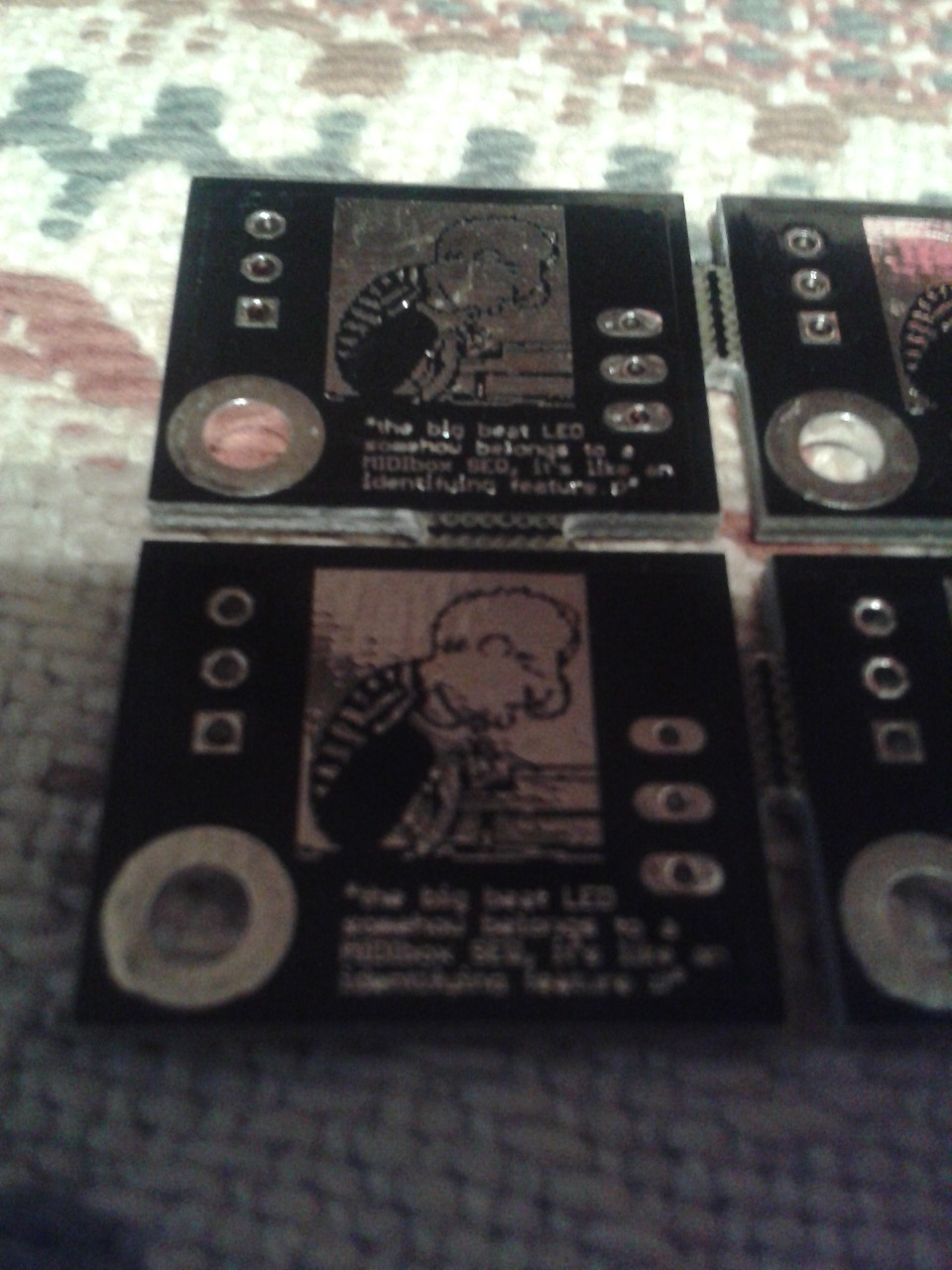
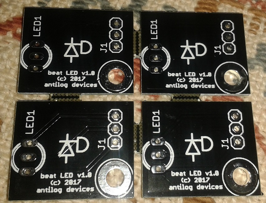
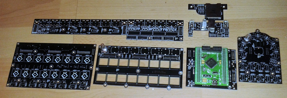
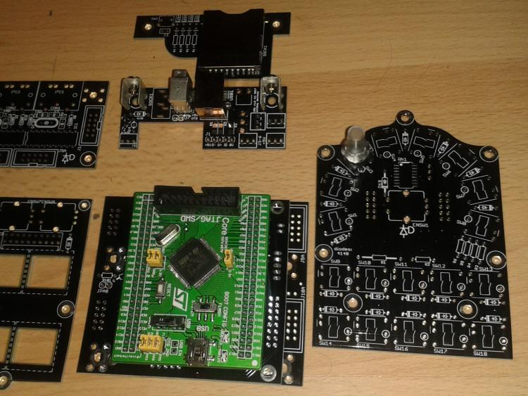
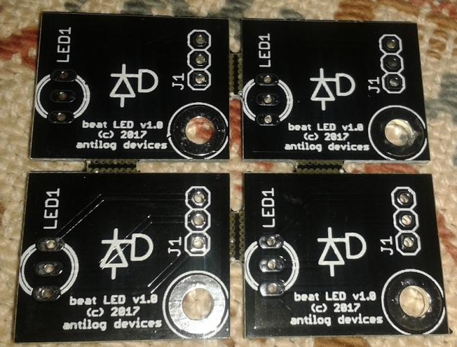
Perhaps a few teaser pics: Closeup of the wCore, note the USB/SD "modules" above: One tricky thing was to mount an LED but not go beyond 160mm x dimension. This was the answer: There was room on the back, so this is dedicated to the guy who loves the Beat LED: A bit hard to capture the mask text, but it reads: "the big beat LED somehow belongs to a MIDIbox SEQ, it's like a defining feature :D"


-
The best thing is you can choose the keys you want: http://matias.ca/switches/ The options like you say are click, quiet click or linear. I though I'd like the linear, but actually I prefer the quiet click. Some people enjoy clicky keys, so no worries there! PCBs are here, unfortunately they didn't do the cutouts for the LEDs, so there will be a delay in testing. I also need to get some parts orders done -- getting there slowly!
-
It's okay, I'm not offended. It's just unclear from your wording whether you were suggesting "You may want tio take a look at some of the matrix keyboard..." in a general sense or for this project. A few weeks ago you were asking for extra headers to use panel-mounted switches, so my initial sense was for the latter. Fact is they _are_ really cool hardware items, and they should definitely be incorporated into more projects. You might have seen Wilba's Cherry Jammer keyboard with a clever velocity sensing mechanism, or I think it's antichambre who was looking at reflectometric light sensors. No DHL today, so another few days to wait at least. :(
-
It's true that some of these layouts could be useful for other projects; I suppose they're somewhat related. It's also a different story doing "bespoke" builds rather than a repeatable project. For instance, the closer spacing means the caps must be cut down (or those custom clear caps, which don't look great IMO), and not everyone is prepared with the right tools. Another thing to consider is how the button layouts work with other hardware. 19mm standard spacing is actually perfect for a 40x2 LCD. Sorry, I'm not trying to be too grumpy. The PCBs were designed over a period of months with the whole build in mind, and the order was placed weeks ago, so it's not changing unless there's a problem with the prototypes
-
It's not that GW, the I2C address is done on the PCB, so the PICs respond to the datastream depending on the states of two pins.
-
Of course, easy mode would be to use an existing PCB and MX-type switches. But those keyboards are built for a specific purpose, as are mine. What will you do with the extra four columns and two rows? Arduino-compatible, but using an SPI-controlled matrix driver. SRIO on a MIDIbox simply updates with the clock tick and requires almost no overhead. (Plus, the former doesn't fit with TK.'s plans of derivative HW that's simple to integrate.) Are the LEDs addressable or always on? The biggest challenge is to get LEDs to illuminate the entire switch. Hopefully the PCBs come tomorrow so it will become clearer to explain, and I'll probably start a new thread for it. MX-type have the LED as THT close to the key, or an aperture on the north edge. This is okay if you have a small glyph to illuminate, but for blank keys it looks bad. Enter Matias, where the entire key is transparent. But there's no room for LEDs, except on the underside as reverse mount. Now try to find a bicolour LED that's bright enough. I did some testing with 2x lensed 1206-ish sized parts. Maybe it could have worked, but it would've required 4 LEDs per switch. This increases the price and still isn't perfect. Here it is. It's not the intended use for these LEDs, but it works well. You can choose R, G or B, but the BLMs support only two of the colours. You could control the third separately, or all three with a different driver. This is the route I'm gonna take, you're of course welcome to try your own methods with existing hardware. Best, Andy
-
I don't think it will work. The display normally initialises on start up. Switching with the power running will likely lead to garbled display pixels. You're also messing with the integrity of the datalines. DIN/DOUT might work, but you'd be sending the data right before switching = corruption. A bit laborious, but you could send the data lines of J8/9 and the displays to additional buffer chips (541 or 125). (It would almost work with the buffers/595s already present, but there are extra signals to deal with.) The outputs of the buffers can be enabled by tying the /OE pins low. Meaning if they're high, no signal passes. You then switch one datastream off and the other on, probably with a short manual delay in between. Resetting the Core would also not hurt, but could be okay without.
-
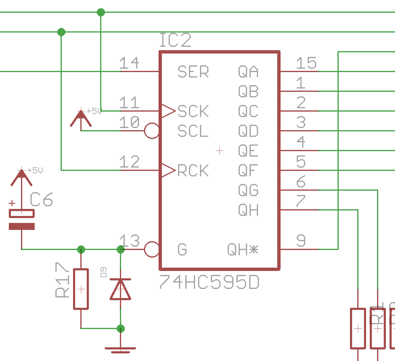
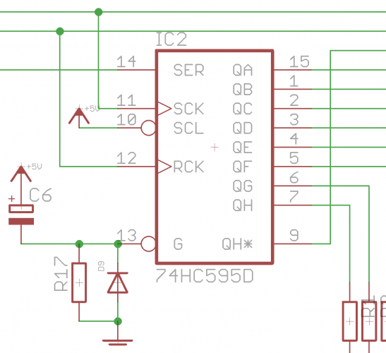
Hi, /OE means output enable, active low (/ or a line on top of the pin name). When it's low, outputs are enabled. When it's high, outputs are tristated/high impedance/open circuit. Notice the DOUT pin 13 is normally connected to 0V/ground. For this to work, you have to charge a capacitor (e.g. 10uF) from +5V to /OE, then provide a resistance to 0V (10k, you choose the delay though). When the power is applied the /OE pin will "see" this as a high logic level, then fall to the low state once the capacitor has charged. Finally, you add a diode to discharge quickly once the power turns off. Anode side to 0V, cathode side to /OE. You can distribute this circuit to many /OE pins; I did the BLM 16x16 in groups of 4. Best regards, Andy
-
The state of outputs on 595 shift registers is undefined on power up. But it's possible to temporarily set the /OE pins (#13) high with an RC delay, meanwhile the Core will have sent a "clear all outputs" signal to the 595s. You could potentially do this with a free MCU pin too. Keep in mind that the /OE pin will be high impedance, which means any transistor bases used as current sinks will be floating = not a good idea. To avoid this, add a pull down resistor of 100k or so to the transistor base.