latigid on
-
Posts
2,524 -
Joined
-
Last visited
-
Days Won
149
Content Type
Profiles
Forums
Blogs
Gallery
Everything posted by latigid on
-
All the best to friends in Munich, stay safe everybody.
-
You and me both, PCB protos expected next week. You can't mix different display drivers on the same signal chain without significant re-coding. MBCV uses two separate ports and is noted as an exception. If you wished to have this coded into MBNG you'd likely have to do it yourself.
-
The 0.96" displays are really nice (hi-res thus sharp pixels) and really cheap. Most also have a carrier board meaning you could mount them easily. The one you found needs an FFC or 0.5mm pitch soldering, so go for the mounted option if you choose this route. I don't think that mixing display controllers is possible without special coding (works for example on MBCV). As far as chaining multiple displays, I know @Hawkeye implemented this for the Programma v0.1 My SCS-OLED boards will have a similar arrangement of rows of 4 OLEDs, which can be omitted in place of switches/an encoder.
-
We're all coming from different backgrounds, with different time commitments and so on. The number one priority is that the board should work, and that's the responsibility of the designer. Many other choices come down to personal preference or experience, which is totally cool seeing as we aren't under contract to provide a specific service. E.g. I will always put decoupling caps near the power pins, and if you don't believe in them (:-P) it's your choice not to populate those components. The direction towards a casing standard is quite smart, because that's often the limiting factor in builds and can contribute majorly to the cost. @Rowan actually suggested that as a direction a little while ago, and it's very doable simply by limiting the PCB height to ~100mm. I don't agree that panel sizes should be equal to a power of two, though there is a loose idea to keep the HP values as even numbers. It's very rational to use SMT, not just because of size and certain availability, but it allows for easier trace routing, double sided placement, closer clearance (look at the registers placed under the dot matrices above), less drill hits etc. And you'll actually find that it's easier than through hole assembly as you don't have to clip leads. Can be much cheaper for components too. Avoid SMT on parts that experience mechanical stress like pots, switches, sockets etc. Personally I stick to through hole design when I can. Sorry for the off-topic discussion, feel free to split if needed.
-
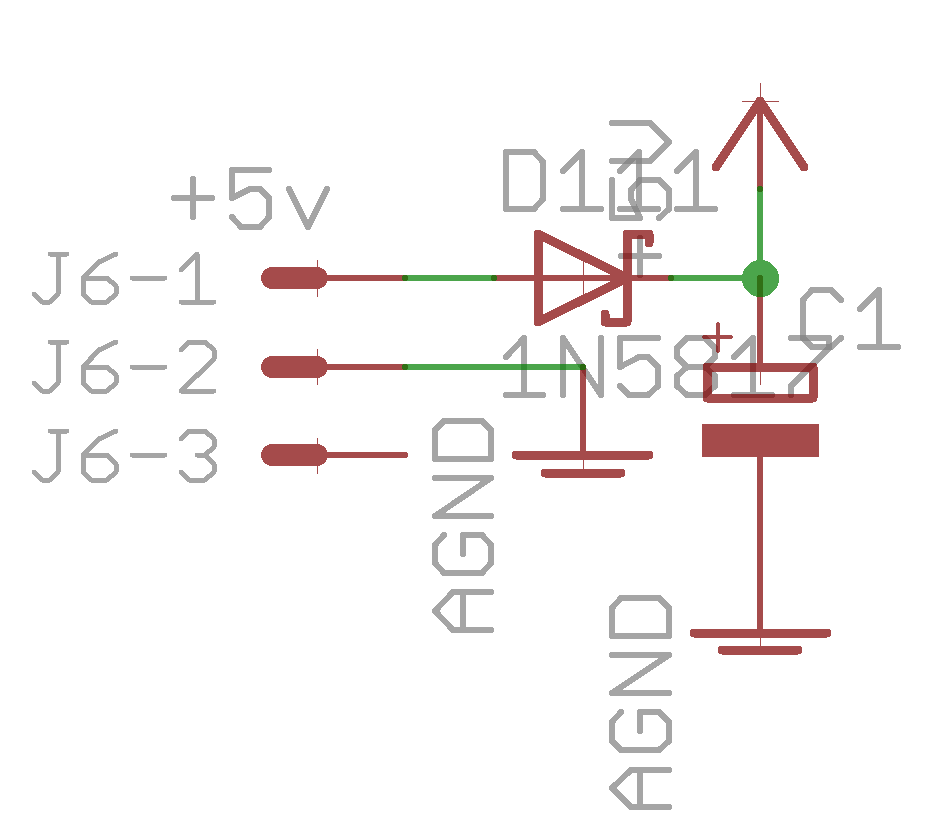
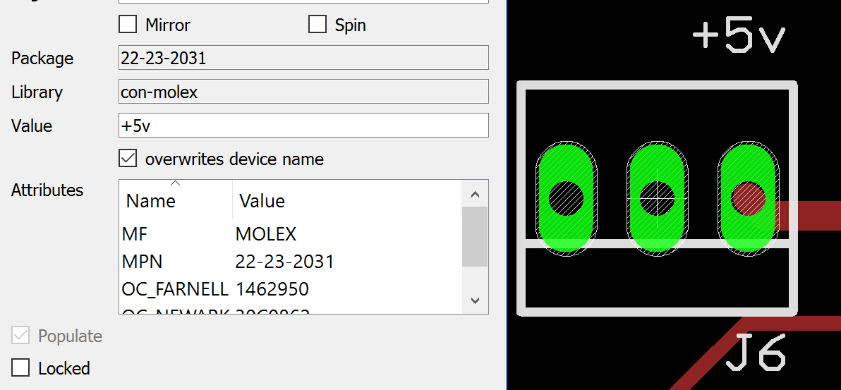
The EAGLE library part has pin 1 on the right as referenced to the schematic: I can't say how this would relate to KiCAD, but it would be great to standardise the power connector on the right relative to the polarity tab on the bottom edge.

-
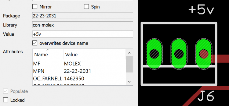
All good, here is the part: http://www.mouser.de/ProductDetail/Molex/22-23-2031/ Also available for next to nothing at Tayda: http://www.taydaelectronics.com/connectors-sockets/wafer-housing-crimp-terminal/serie-2500-2-54mm.html Pin 3 NC Pin 2 0V/ground Pin 1 +5V Lots of edits today: it's of course possible to use an ordinary 100mil breakaway header in place of the Molex part. Best, Andy
-
If the current consumption is "high" then it makes sense to wire the power lines in parallel EDIT: I should say "star wired." This sends the return current back to the source rather than influencing other modules in the chain. I only asked because I was wondering about the 2-pin connector at the top on the rear side. Flexibility, even if it's "over designed," can extend the device beyond its original purpose.
-
I don't agree; I've read about cases where decoupling caps were the difference between a chain of serial shift registers working or not. A fly-wired cap would be just as effective as your current layout -- the closer to the power pins the better.
-
Nothing wrong with SMD, most of my upcoming modules will have some SOIC/1206. It's better to learn sooner or later. Edit: nothing stopping @Psykhaze adding 2HP to his front panel. TPD looks cool, but shouldn't the decoupling caps be nearer to pin 16? Without trying to spread FUD, I wonder about lots of blinkenlights in a Euro case when potentially combined with analogue modules. Do you have any data on power supply recovery when everything's humming? It could be okay with the PSU driven from the SEQ or at least isolated from the Euro rails. For my latest work, I include a 3-pin 100mil/2.54mm Molex header with the centre pin 0V/ground and +5V on the right when the polarity tab is at the bottom of the connector. The left pin is NC. Could we consider a standard perhaps?
-
Very cool, like the dub vibes!
-
Exactly, every ADC chip requires select lines. Notice AINSER64 further multiplexes the inputs with 4051 chips for a single 8 channel ADC and generates a 3-bit "address" to specify what input a 4051 should scan at a given time. This is synchronised in software to map each "pot position" with its current value.
-
How many AINs were you thinking? STM32F4 has 8 ADCs and a few of us are looking into how well this works. It's easier with known voltage maximums that you define through a resistive divider like a pot rather than CV which needs protection from over- and undervoltages etc.
-
No question, go for STM32F4. For a start, LPC17 carrier boards are not available AFAIK and they changed the pin config of the MCU breakout which further reduces the compatibility. F4 is faster, has more RAM etc. BTW, if you only have a PIC Core at the moment, you have a SEQ V3 :). Perhaps you meant STM32F1, the first gen. Core32?
-

Toggle a group of AINs and show corresponding submenus
latigid on replied to tago's topic in MIDIbox NG
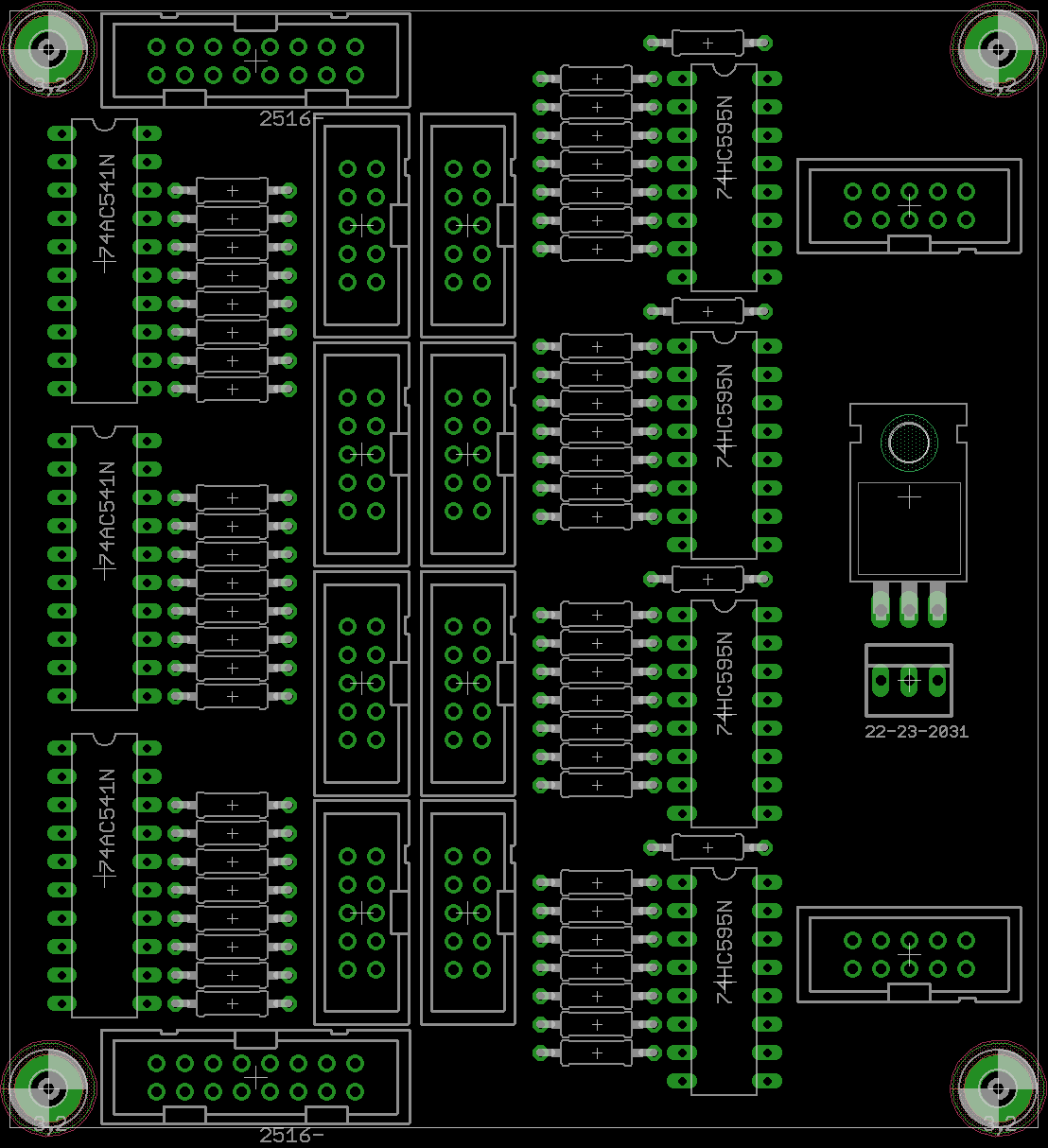
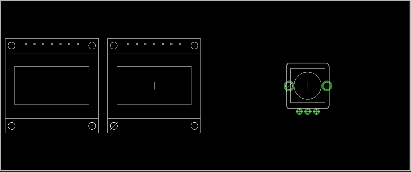
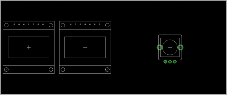
Max. 64 displays (128*64 graphical 0.96" OLED based on SSD1306) are possible with extra chip select lines (e.g. PCB shown below), each of the 2*5 connectors drives up to 4 displays.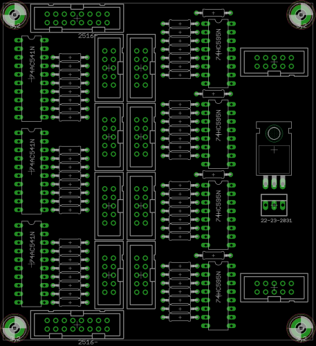
-
Toggle a group of AINs and show corresponding submenus
latigid on replied to tago's topic in MIDIbox NG
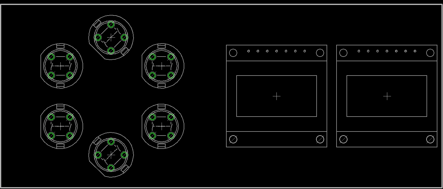
Keep in mind that Programma v0.2 will use illuminated encoders instead of LED rings. Less holes and more flexibility (colour coding for different sections, modulator polarity etc.) As far as a universal controller goes, you get dynamic labelling of encoder functions and "pages" for different synths, different patches etc. -- the ultimate solution! It's also a 4*4 grid, so you're free to mix and match with different types of boards, like in the Modulbox concepts Jerome is putting forward. This is intended as a MBCV control surface, but it too could be adapted: These are Standard Control Surface (SCS) boards which can have 1,2 or 4 OLEDs attached in various configurations (note the 6 buttons are now in the centre):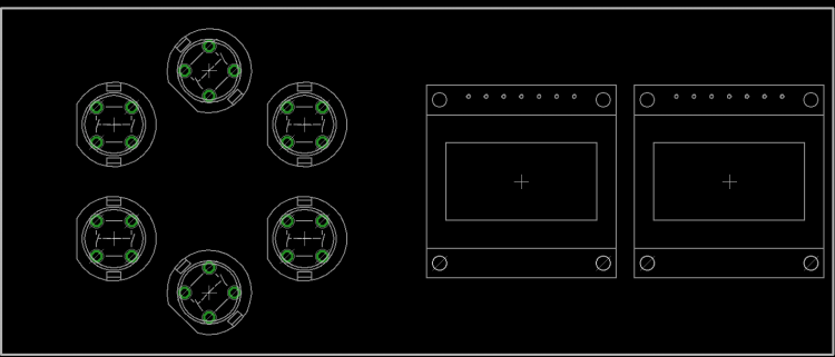
-
@Psykhaze, well, the question is: why doesn't everybody just veroboard their switch/LED/pot boards? The ironic thing is this was the original intent of MIDIbox -- custom controllers, and it was out way before off-the-shelf MCUs like Arduino etc. Modulbox and pro-PCBs in general sacrifice this more personal approach for robust and easy to handle solutions. I'm not saying it's a bad thing, but the inevitable outcome is that newbies with no concept of what MIDIbox or a shift register is will come and expect instant results. Be careful what you wish for SDIY (if we can extend this to MIDIbox) is a community with a wide range of abilities. I would certainly not expect a newb to understand everything from the start just by looking at uCapps and the wiki. Perhaps with your efforts there some info can be clearer. It's just nice to start with a PCB that's almost guaranteed to work so you don't get disappointed. It's very true about taking the time and effort to learn about the basics in a managed way. Best,
-
Of course you can use veroboard, but it's flimsy compared to FR4 PCBs and the copper can delaminate. It's also quite time consuming (not to mention error-prone) to wire up the traces, and when that's done normally signal integrity/RFI is poor due to unintentional antennas, lack of ground plane coupling etc. It's also impossible to use non-100mil/2.54mm spaced components without drilling extra holes, which are then poorly fixed. Basically, veroboard is, like, so 2005. With dedicated PCBs, one person (or a group) spends lots of time preparing the layout and risking many bugs in the first version. But after, copies are made and everyone can enjoy. @Psykhaze, it's very ironic of you to suggest veroboard when you propose simple PCB layouts (professionally made I suppose) with only a few switches/LEDs/pots etc. for Modulbox. As far as Core32 PCB availability goes, I'm considering an alternative layout with a few extra tricks. Perhaps also a "slim" MIDI IO with 2.5mm jack connectors .
-
No, you can't handle encoders this way.
-
Hmm, I'd be interested in the pots/knobs if they're available. Could even do one packet to DE and I can split with ilmenator.
-
In the end I've ordered PCBs with the top "track" and scale info labels removed. I kept the note and divider labels. They're minor functions with much smaller size than the "main" labelling of GP/function buttons, so not very intrusive IMO. They're in the "right place" and I doubt they will become obsolete, especially as you've said you're not actively developing the V4L much further. For the suggestion that because everything can't be labelled explicitly, no function should get extra labels, I humbly disagree. Looking through the V4L user manual, many modifiers such as groove/delay/humanizer are intuitive as the "amount" is proportional to the GP button pressed, so you'll know exactly what you're getting. The other four I mentioned are quite confusing without a guide (paper template... hmmm) and are "critical" functions when performing live to maintain timing or pitch. The "lite" version of the SEQ is meant as a lower cost version of the SEQ, and an even lower cost is achievable with a transparent case. Some might find the PCB labels annoying or sub-optimal, or might not even like the colour of the PCBs (will be yellow/black )! In this situation, they're free to design their own opaque case with custom labelling. I'm looking forward to the PCBs and a new direction for SEQ V4L. Best, Andy
-
Stupid question: you're using the 4 pin SIL header to send the data right? Not the 2*5 DIL used for BLM 16*16+X?
-
How did you diagnose that it was "not working?" I.e. really no good MIDI transfer? (Are the tracks assigned properly?) Are the interconnections verified? Do the status LEDs light up? Clock data should be set on starting a sequence, so this is visible as continuously lit.
-
I'll try to explain what I meant. The labels are not intended to indicate LED function but instead give the position of the GP button to press when in certain modes. For example, I wouldn't immediately remember an Ionian mode was on GP#14 when selecting a scale, nor a quick selection of 1/16T for tempo/divider on GP#11. The notes are directly associated with the GP button, maybe we could even consider a "303" type of note entry recording with them. For me, the clear, tempo, scale, and mute functions are the least intuitive, but I haven't built nor used a SEQ V4L, so I can't say how quickly one learns these off by heart in practice. As we've discussed before, some people are more adept at menu programming than others :). I agree that the top positions are the most separated from GP buttons, and probably not too hard to memorise (I'm sure they'd be welcome for debutants though :) ). Does this make more sense? I know for my own case I would rather have these labels than not. Best, Andy
-
Thanks for checking, to clarify do you mean just the extra labels on the top of the board or scale/note/divider as well?
-
Final PCB design labelling. I added some helper labels like what each "track layer" does, scale types per GP button, keyboard notes (transposition) and dividers for tempo. If there's no further suggestions I'll probably place the order within a week.