

Antichambre
-
Posts
1,291 -
Joined
-
Last visited
-
Days Won
101
Content Type
Profiles
Forums
Blogs
Gallery
Everything posted by Antichambre
-
Oh! Without worrying too much about, I think this is an important aspect of your machine for finishing... Something like the 1LS096-16.0 should be the best, I know it's a question of taste but I really like the frosted round lens. + But this one is not distributed in 16mm, no stock anywhere. And I'm afraid the 15mm is too short. The only solution is to order it from APEM, but they want minimum quantity. Should be included in a future version of the essential kit maybe? Best Bruno
-
I know you suggest the 3F 1S 19mm. But on all the pictures it seems high, like 4 or 5mm over the front panel surface. I just wanted to see if the 5G 1LS 15mm(which can be easily sourced too) could fit.
-
I like this blue too... Is it the picture? If it's not a the picture and not a color accident in the dosage I'm interested in this color code. Finally what is the best height for the Apem? How much is a 15mm button flush at rest?
-
Maybe better for him to start from beginning, to understand common regulator before trying a more complex option. He just has some SID modules and a core8 classic mbhp, not a MB6582 pcb, it's less power too. It will work correct if he follow the basics. After that first thing achieved, he is free to investigate more and dig in your solution to optimize his already working synth.
-
7V is not a big drop for a 7805(not too much hot) and you can reduce it to 4V by supplying the 7805 by the 7809. I prefer Linear regulation for Audio purpose but I'm a purist for sure ;)
-
lol, I'm a lazy beta tester too, I totally assume that I preferred waiting for you Guys, instead of find some difficult part by myself and make mistake e.g. rgb leds And finally now I prefer waiting for the new UI boards set, the one which matches with the definitive enclosure. Have a good day everybody!
-
You can use 12V input for both 7805 and 7809(same external adapter), the column title is Minimum Input Voltage.
-
It depends, for a 7809 regulator a 12V input is enough, check the datasheet of regulator you choose. but in general:
-
I did not understand for a moment that you wanted the original files, I thought rather a pdf format. Sorry Maybe I'm wrong... but for me retro-engineering is analyzing a hardware and extract the data from it, not recreating something by reading a schematic or a text file, cause in both cases the data are already available. Best Bruno
-
As you said, if you've got the config file then you've got the position of the elements over the SPI chain, like schematic you just have read it, not(more) a big deal. So if you want to respect the V4+ config file with your own board, that's possible too, without waiting for Andy to get time to perfect and release his schematics ;) Anyway...
-
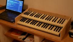 I always like your wood style too!
 -
Wat is the use of the Microphone? :)
-
I suppose you will use the Marquardt switches just to replace the Mattias ones(I supoose they are the "christmas tree ones" you don't like, Humm). Then you will need the PCB set from Andy and Peter, you need the Jog menu and Encoders boards, you just have to replace the LeMec boards by your own, so no trouble... if you really want to do that... I you don't want to use any Andy's Boards then you can go from scratch, with the pinout of J8/9 and a blank Config file, no?
-
I dont know the best answer but, there are also compatibles others references from others brands... I put this one in my KPR-77, seems good, they say "Long Life Type". https://www.alps.com/prod/info/E/HTML/Tact/SnapIn/SKQE/SKQE_list.html 1.57N = 160gf, 2.57N = 260gf
-
I'm fine thank you. Don't worry for that, It's just that you do not come here often enough There's no trouble, your version is a MB SEQ V4, this new one is MB SEQ V4+ They don't change the Version because the App, the Sequencer engine remains the same, the UI is the only change.
-
Hi Hal, Hope you're fine... Midiphy is not a front panel, it's a new MB dedicated webshop! The MB SEQ V4+ relates to the new frontpanel. The new core is Andy's wCore based on waveshare core407 I let Andy or Peter answer to your question ;) Cheers Bruno
-
SID Modules with 8580 must be supplied in 9V! Not 5V PSU is on the diagram: http://ucapps.de/mbhp/mbhp_sid_v3.pdf Best Bruno
-

dipCoreF4 and dipBoardF4, a compact Core.
Antichambre replied to Antichambre's topic in Design Concepts
Hi, After some try, I'm able to use the second USB OTG, the USB_OTG_HS in full speed with the embedded FS phy. The idea is to keep the USB_OTG_FS as it is in dual role with ID pin. And add the USB_OTG_HS in FS Host Only, to connect a B-device only. It works fine for HID(Keyboard and Mouse), I will complete the classes with MSC(Mass Storage), maybe MIDI of course. Here, MIOS Studio is connected in USB(normal one) and I plug a mouse first then a keyboard to the other USB: ( did this test with a modified wCore) This is very difficult too implement on a mbhp disco or wCore cause the DP/DM pins are used for J8/9 SI/SO(PB14/PB15). BUT! I can do it on the dipCoreF4, by moving SI/SO on other alternate function pins. => Then like I said I will make some changes on the STM32F405 pins and on MIOS32 side. Add pins for DP/DM and Over-current/VBUS Drive GPIO of the second USB on the dip40(other extra pins). And modify the dipBoardF4 for that purpose of course. Have a good WE Best Bruno -
CC-Looper (4ch controlchange looper)
Antichambre replied to Phatline's topic in MIDIbox User Projects
Digikey has 4 references in stock: https://www.digikey.com/products/en/connectors-interconnects/circular-connectors/436?k=&pkeyword=&pv69=367&sf=0&FV=160000f%2C35c00b1%2Cffe001b4&quantity=&ColumnSort=0&page=1&stock=1&pageSize=25 Mouser: https://www.mouser.fr/ProductDetail/Switchcraft/62PC7FS?qs=sGAEpiMZZMtAYTMy7wxAr13KGyWtEeUKoNdfSl%2fLnxo%3d You can also use DIN8-270° Like this one https://www.mouser.fr/ProductDetail/CUI/SDF-80J?qs=%2fha2pyFadugMOpW%2fmtqhOULV0YI0Vc4gflcNSjtzoJM%3d which is cheaper. -
CC-Looper (4ch controlchange looper)
Antichambre replied to Phatline's topic in MIDIbox User Projects
He wants 2 regular MIDI Out on the same connector, If he chooses a DIN5-240/270° he will not ba able to connect a regular DIN5-180°(when only one MIDI out needed). but he can choose a DIN7-270° to avoid any problem with a SYNC24 pinout. -
CC-Looper (4ch controlchange looper)
Antichambre replied to Phatline's topic in MIDIbox User Projects
I figured you'd need sysex for the commands to leave the CCs totally free for record/play. -
CC-Looper (4ch controlchange looper)
Antichambre replied to Phatline's topic in MIDIbox User Projects
Not very regulatory but you can use the two other pins of your DIN5 Out and make a short Y cable Male to dual Female. This will not be a problem to connect a single and regular MIDI cable too.- 27 replies
-
- 1
-

-
- cc-recorder
- controlchange looper
- (and 1 more)
-
CC-Looper (4ch controlchange looper)
Antichambre replied to Phatline's topic in MIDIbox User Projects
You don't need, it's a THT ;) -
CC-Looper (4ch controlchange looper)
Antichambre replied to Phatline's topic in MIDIbox User Projects
I understand now, you did not explain me that you wanted to use the mini-USB directly to the back of your machine. The connector will not flush the backside, you will need a cut-out of the size of the plastic body connector part. Visually this is not beautiful but mechanically it's better and stronger. Your schematics seems fine for me. Your project could be a good companion for the LoopA. Do you plan to implement Sysex commands? Best Bruno -
dipCoreF4 and dipBoardF4, a compact Core.
Antichambre replied to Antichambre's topic in Design Concepts
Yes it is! The 2 lsb bits ///////////////////////////////////////////////////////////////////////////// //! Sets one or more LEDs to the given value(s) //! \param[in] leds mask contains a flag for each LED which should be changed //! \param[in] value contains the value which should be set //! \return 0 if initialisation passed //! \return -1 if no LEDs specified for board //! \return -2 if one or more LEDs not available on board ///////////////////////////////////////////////////////////////////////////// s32 MIOS32_BOARD_LED_Set(u32 leds, u32 value) { #if defined(MIOS32_BOARD_STM32F4DISCOVERY) || defined(MIOS32_BOARD_MBHP_CORE_STM32F4) #if MIOS32_BOARD_J15_LED_NUM >= 1 if( leds & 1 ) { // LED4 (Green) MIOS32_SYS_STM_PINSET(GPIOD, GPIO_Pin_12, value & 1); } #endif #if MIOS32_BOARD_J15_LED_NUM >= 2 if( leds & 2 ) { // LED3 (Orange) MIOS32_SYS_STM_PINSET(GPIOD, GPIO_Pin_13, value & 2); } #endif #if MIOS32_BOARD_J15_LED_NUM >= 3 if( leds & 4 ) { // LED5 (Red) MIOS32_SYS_STM_PINSET(GPIOD, GPIO_Pin_14, value & 4); } #endif #if MIOS32_BOARD_J15_LED_NUM >= 4 if( leds & 8 ) { // LED6 (Blue) MIOS32_SYS_STM_PINSET(GPIOD, GPIO_Pin_15, value & 8); } #endif if( leds & 0xfffffff0) return -2; // LED doesn't exist return 0; // no error #elif defined(MIOS32_BOARD_DIPCOREF4) #if MIOS32_BOARD_J15_LED_NUM >= 1 if( leds & 1 ) { // LED0 (Green) MIOS32_SYS_STM_PINSET(GPIOC, GPIO_Pin_6, value & 1); } #endif #if MIOS32_BOARD_J15_LED_NUM >= 2 if( leds & 2 ) { // LED1 (Orange) MIOS32_SYS_STM_PINSET(GPIOC, GPIO_Pin_7, value & 2); } #endif if( leds & 0xfffffffc) return -2; // LED doesn't exist return 0; // no error #else return -1; // no LED specified for board #endif } 1206 package https://www.mouser.fr/ProductDetail/576-1206L150THWR No, dipCoreF4 pinout will not change... I'm working on something which will maybe change STM pin assignation. but dip-40(48) will keep the same pinout and function. Try to do not put any component in the dip40 area. It is possible that I add some feature and pin, somewhere in the alignment of 41-43 or 44-48. Best Bruno