

Antichambre
-
Posts
1,291 -
Joined
-
Last visited
-
Days Won
101
Content Type
Profiles
Forums
Blogs
Gallery
Everything posted by Antichambre
-
You're not obliged to put a CS, a MIOS8 Core wih MIDI I/O + SID Module are enough, PIC must be a 18f4685, as Andy said a good and linear power supply is necessary for the SID. On SID v2 Application User manual page you will find Sysex and CC implementation. Best Bruno
-

LoopA V2 Introduction, Features & Support Thread
Antichambre replied to Hawkeye's topic in MIDIbox User Projects
Yes of course it needs more than 5V power supply for CV purpose. -
LoopA V2 Introduction, Features & Support Thread
Antichambre replied to Hawkeye's topic in MIDIbox User Projects
It seems you put CV/Gate Outputs :) Great! Add it in the Main features list, this is an important point. -
dipCoreF4 and dipBoardF4, a compact Core.
Antichambre replied to Antichambre's topic in Design Concepts
And Mike... this is a beta version so after testing it if we feel that there's something to change I will do ;) -
dipCoreF4 and dipBoardF4, a compact Core.
Antichambre replied to Antichambre's topic in Design Concepts
Hi Mike, I do not see what is the point, when I have the same voltage on VBUS or somewhere outside and it makes me loose some pin. Humm, yes but this is not a primary features, this is sized for MIOS32 before everything. Using the dipcore in an existing mios8 app will obviously need some adaptation, put I tried to make sure to have the least to do. Example for a sammichSID, Screen will be changed and connected directly to the dipcore, 5V from sammich pcb will be connected to VBUS(pin44), 3V3 of the dipcore will be not connected, etc... Of course you can power the dipboard with that USB, I add another PTC Fuse on the dipBoard for that specific configuration e.g. in development mode. Yes like any existing 32 bit mbhp. I don't understand -
dipCoreF4 and dipBoardF4, a compact Core.
Antichambre replied to Antichambre's topic in Design Concepts
Between Your App USB connector and pins 46/43 some rules are usually followed to preserve differential pair DM/DP. USB signal pair traces should be trace-length matched. USB 2.0 Full speed (12Mbps) can survive a 1mm difference. Avoid 90° angle in trace. I used to round it a little bit. Hope this helps you... -
dipCoreF4 and dipBoardF4, a compact Core.
Antichambre replied to Antichambre's topic in Design Concepts
In the dipCoreF4 the internal plane 1 is divided like this: Between VBUS and internal +5V there's a PTC fuse F1 which protect VBUS from over-current. You can use VBUS(Pin44) as output and supply your App PCB from dipCore USB. But F1 will not protect VBUS from your APP board 5V load. I didn't think it like that, in your case, you will design a dedicated box for your CC looper UI-PCB then you will put an USB connector or an external power somewhere on that box. And in this case you're not obliged to use and solder the dipCoreF4 USB. The dipCoreF4 is like a component and your UI-PCB provides the 5V to it. -
dipCoreF4 and dipBoardF4, a compact Core.
Antichambre replied to Antichambre's topic in Design Concepts
From the same external source where you connect VBUS of the dipCoreF4, Simply see it like a component, you've got to supply it in 5V and it will provide you the 3.3V. The Core is the 3.3V regulation too(this is not different to the others cores). Remember, there's a 74HCT541 onboard, all J8/9 and J19 output pins are in 5V. Usually this level shifter is on the mbhp, but here the Core is dedicated to MIOS32 then I put the 541 directly on it. You can't internally connect to physical pins to the same signal? Strange, but I can't help on this, I don't know Kicad. -
dipCoreF4 and dipBoardF4, a compact Core.
Antichambre replied to Antichambre's topic in Design Concepts
Right! Refer to this chart for changes: For easier routing PB2 was replaced by PA4, in MIOS32 side also. Not USB only, you can use external 5V connected to VBUS on Pin44 or on J1A or J1B of dipBoardF4. I'm currently preparing an USB board where VBUS from type B connector(device mode) is switched off when VIN(external power) is present... Best Bruno -
dipCoreF4 and dipBoardF4, a compact Core.
Antichambre replied to Antichambre's topic in Design Concepts
Seems fine, great! Think to set 3V3 Power supply pins as Output type! To avoid any mistake. VBUS(5V) is an Input type of course. -
dipCoreF4 and dipBoardF4, a compact Core.
Antichambre replied to Antichambre's topic in Design Concepts
NB: A Discovery can flash it onboard. SWDIO and SWCLK are on the DIP40 pin 13 and14 (old xtal IO). 2*dipCoreF4 + 1*dipBoardF4 is fine for you? Bruno -
dipCoreF4 and dipBoardF4, a compact Core.
Antichambre replied to Antichambre's topic in Design Concepts
Someone else is interested to test this Core? I'm in holidays and I want to order the boards quickly. Best Bruno -
Ohhh yes I remember this issue now it was for the SSD1322 not SSD1306, and it was the opposite(no init on upload). thx Peter
-
Yes remove the Cap fist and try. Could you share the spec and the origin of the one you've got? Could be interesting to know...
-
Which value did you put for the reset cap and resistor? http://ucapps.de/mbhp/mbhp_lcd_ssd1306_single_mios32.pdf Maybe the cap takes too much time to load increase resistor, decrease the cap(or remove it)
-
Et.... There's no compromise between our solution and their commercial one. Means, if you want the same perfect solution as their, the box you will have to build might not be cheaper than their 'midibox' at 49$. Then it's a choice you have to make ;) But thank you for all your research, that's kind. Best regards Bruno
-
lol Thank you for that now I'm sure pedal I/O are regular CMOS 5V levels. They surely protected the input for over-voltage, zener or something else. That's the question, Even if there's 5v on the ring it stays the internal UART output(strange) maybe they put something like a big capacitor to maintain the level at 5V (only in input mode of the cable). And this last is removed from the circuit when in output mode(?)... but in input mode the uart output is the power source !!!??? I don't like that. So you bought it and opened it? If it's the case send us the picture, please. For you to know that I checked my diagram and verified signal on waveform monitor before sharing with you, and there's no noise, my first cable made was a 5 meters cable(the length between my setup and my lab) ;) Best Bruno
-
Sorry this module doesn't exist, the ssd1306 is supported by the 'universal' one... I'd got this issue by the past but I don't remember how I solved it... :/
-
Did you try to change the lcd type in your Makefile? # $Id: Makefile 1820 2013-09-01 15:44:33Z tk $ ################################################################################ # following setup taken from environment variables ################################################################################ PROCESSOR = $(MIOS32_PROCESSOR) FAMILY = $(MIOS32_FAMILY) BOARD = $(MIOS32_BOARD) #LCD = $(MIOS32_LCD) # explicitely select the correct LCD driver # KS0108 is supported by the "universal" driver # please configure the bootloader info range accordingly # with the bootloader update application LCD = ssd1306 If not, try it, recompile and upload your app and tell me...
-
If it's necessary, it's also possible to put a Male or Female micro-match on board bottom at one side of the ribbon. that's fine :) Have a good day Bruno
-
Hi did you configure your bootloader? Best Bruno
-
Hi Andy, Not to stack, just to disconnect if necessary(maybe not necessary). Just wanted to be sure you're aware of the reversed footprint between a paddle and a connector, and that you made that choice consciously ;) It's fine :) I've got my answer thank you. Bruno
-
@latigid on Question! :) For the new micro-match connector, you choose to put only paddle board on top with the possibility to put Male or Female connector on bottom ? Am I right? Thank you Bruno
-
dipCoreF4 and dipBoardF4, a compact Core.
Antichambre replied to Antichambre's topic in Design Concepts
I put tented via on both board for easier soldering and better silkscreen... -
Assembly test of unpainted SEQ v4+ case , left handed jogwheel
Antichambre commented on Hawkeye's gallery image in Members Gallery
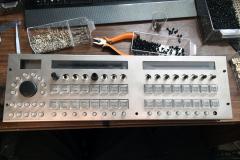 I'm strangely left handed for the fork and knife only, it seems like I'll be here too