

Antichambre
-
Posts
1,291 -
Joined
-
Last visited
-
Days Won
101
Content Type
Profiles
Forums
Blogs
Gallery
Everything posted by Antichambre
-
first, -150 to 150 is not a regular range, better to use 2n value and use bit shifting to divide or multiply by 2 E.g: 16383 >> 7 = 127 signed <> unsigned conversion depends on what you want exactly, and I don't understand exactly what you want to do ???
-
Not without changing MIOS32 code, what I will not advise But if you want to try it anyway everything happens in (root)/trunk/programming_models/traditional/main.c The Hook is MIOS32_MIDI_Receive_Handler(APP_MIDI_NotifyPackage) in TASK_MIDI_Hooks. you will need to know about freertos. Good luck ;)
-
This is normal, MIDI processing in MIOS32 is a periodic Task called every ms. So if you push your button just before the task you will get " 100-200us " if it's just after it will be something like 1ms.
-

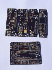
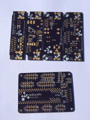
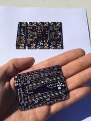
dipCoreF4 and dipBoardF4, a compact Core.
Antichambre replied to Antichambre's topic in Design Concepts
Thank you :) I really like this moment, when thing becomes concrete, when I can touch it ;) -
From the album: dipCoreF4
-
From the album: dipCoreF4
-
From the album: dipCoreF4
-
dipCoreF4 and dipBoardF4, a compact Core.
Antichambre replied to Antichambre's topic in Design Concepts
Hi, I received the dipBoard32 and the modules this morning. dipCoreF4 takes much time to fab because it's a 4 layers. Some small mistakes on the silkscreen but everything else seems fine :) The BOMs for dipCoreF4 and dipBoardF4 are now available on their respective dokuwiki. The BOMs for the Modules are coming soon! Best regards Bruno -
No of course, but now you know unsolder a smd chip is impossible with an iron, better to call a friend who has an hot air station or buy one cost is 50$ for a chinese one ;)
-
It's the same on the LPC board ;) http://ucapps.de/mbhp/mbhp_core_lpc17.pdf in red! :) Have good time with your Seq! Bruno
-
dipCoreF4 and dipBoardF4, a compact Core.
Antichambre replied to Antichambre's topic in Design Concepts
I will explain a bit more that part: This J15 port is enough to connect multiple SPI oleds. Yes! You can use CS1(RC), SDA(SO) and SCLK(SC) to connect some 595 registers in SPI, they will give you how much OLED CS lines you want... SDA is the serial out and SCLK is your clock for your SPI chain and for the OLEDS. CS1 is your RC for the registers. DC is only connected to the Oleds. The thing is to connect all Output Enable pin(OE) of the registers to CS2(which is normally tied to ground on a DOUT module) When you want to refresh the registers output(refresh your Oled CS lines) just put their output in High Impedance using OE(CS2) and the oleds will not receive any data cause they are not selected. Once the registers are refreshed, enable their outputs by putting CS2 high and send data or command to the OLEDS. -
dipCoreF4 and dipBoardF4, a compact Core.
Antichambre replied to Antichambre's topic in Design Concepts
Yes of course it's fine, you can connect a second with J15.CS2, for more than two you will need to write your own driver to manage the multiple CS lines, with some 74HC595, this is what I did for the OLRE16. -
Totally right this is just an led. @Narwhal TK does mention of it on the MIDI-IO Page from ucapps(bottom of the page) http://ucapps.de/mbhp_midi_io.html Put the 47 Ohm it will work, don't take care about MIDI specs, there's no beads here.
-
normally if you put 47 Ohm resistance instead of 220, all optocoupler will work correctly. the 4N37 also. Even if I think this optocoupler is not the best for midi app. but this seems not to be the issue. Yes you're not alone, the problem is not the Core but xoxbox design. https://forums.adafruit.com/viewtopic.php?f=12&t=82849
-
Hello, Did you put 220 Ohm or 47 Ohm on the outputs lines? R21/R22 and R26/R27 Best Bruno
-
From Adafruit I think it matches, but check. https://learn.adafruit.com/monochrome-oled-breakouts/downloads Best Bruno
-
In general we have no reason to refuse your enlightened opinion too ;) Have a good day Bruno
-
??!... humm I didn't watch in the BOM tool. Res/SD board specifies approximately(~)1K in dokuwiki. I was looking for more precise value. So. Sorry Agree. but . Usually each color needs its own value to get a homogeneous brightness. We all know that, objective so ;) Thought you already made some tests to get the good looking pictures of the leds on your website. Bref. Thank you both Bruno
-
@latigid on @Hawkeye Hi Andy, Peter, I want to reuse your rectangle leds in my project, because they are available on your webshop. You share the resistor value for each color on the website but only @5V. Maybe you did the same @ 3.3V (which is the voltage of the SD_RES). Could you share it? I know I can calculate it based on values@5V but I'm a lazy beta tester ;) Thank you Bruno
-
http://m.bareille.free.fr/midithrubox/midithrubox.htm old school! From the same website "This patch bay MIDI is designed to use with a sequencer/computer, a master keyboard and 8 MIDI instruments." http://m.bareille.free.fr/mpb3/mpb3.html
-
Too much limited for me, no merging or distribution, no channel routing, muting or other event filtering. I want mOoooore ;)
-
Like me!? you don't want to connect/disconnect any machine anymore? I think an external expansion will be possible for the Seq V4+( as it is ), there's already too possibilities to connect it, the Line Driver and the MCAN... I will build this seq too, and try this expansion once I've got it, so go for this sequencer! 16 MIDI outputs(and more) will come after. Best Bruno
-
dipCoreF4 and dipBoardF4, a compact Core.
Antichambre replied to Antichambre's topic in Design Concepts
In mios32_config file add : #define MIOS32_DONT_USE_IIC and the pin of J4 will not be initialized as I2C. Then initialize the pin as Input e.g. PB6 GPIO_InitTypeDef GPIO_InitStructure; GPIO_StructInit(&GPIO_InitStructure); GPIO_InitStructure.GPIO_Speed = GPIO_Speed_50MHz; GPIO_InitStructure.GPIO_Pin = GPIO_Pin_6; GPIO_InitStructure.GPIO_Mode = GPIO_Mode_IN; GPIO_InitStructure.GPIO_PuPd = GPIO_PuPd_NOPULL; GPIO_Init(GPIOB, &GPIO_InitStructure); Finally to get value: u8 value = (u8)MIOS32_SYS_STM_PINGET(GPIOB, GPIO_Pin_6); Best Bruno -
dipCoreF4 and dipBoardF4, a compact Core.
Antichambre replied to Antichambre's topic in Design Concepts
Hi Phatline, You can use the pin you want, all pins are GPIO as first function. Just don't take something already used(SDcard, midi, etc..). You want input then don't use 5V level output pin(SC, SO, RC) like the one of J19 or J8/9, they can not be input. But you can use J4 for example. Best regards Bruno -
You got it! ;)
