

Antichambre
-
Posts
1,291 -
Joined
-
Last visited
-
Days Won
101
Content Type
Profiles
Forums
Blogs
Gallery
Everything posted by Antichambre
-

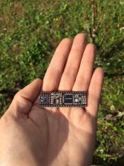
dipCoreF4 and dipBoardF4, a compact Core.
Antichambre replied to Antichambre's topic in Design Concepts
Sorry guys!!! There will be some delay :( Fab made an error, I've found a workaround for this one as I can check everything but the other boards are just good for trash. They connected VBUS to Ground internally, via and pad are connected to the wrong internal plane I think. Fortunately VBUS and 5V are separated by a fuse, there's no more protection but I can switch it On And check everything before they fab it again. -
dipCoreF4 and dipBoardF4, a compact Core.
Antichambre replied to Antichambre's topic in Design Concepts
They are here :) -
 Sorry @Hawkeye I uploaded 3 times the same 2 pictures. :/ But Album upload has always this strange behaviour of saying I don't want for finally doing it.
 -
From the album: dipCoreF4
-
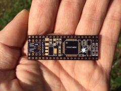
From the album: dipCoreF4
-
MIDI8 is compatible with any 32 bits core. MIDI8 = 2x MIDI-IO.
-
Unified midiphy SEQ v4+ case backside
Antichambre commented on Hawkeye's gallery image in Members Gallery
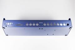 Always! As far as I remember. That's exactly the shade of blue in which I painted my first moped hihi :) There's some red pigment in this blue, name is "bleu nuit" in french ;)
 -
Unified midiphy SEQ v4+ case backside
Antichambre commented on Hawkeye's gallery image in Members Gallery
Yes Fantastic work!!! -
dipCoreF4 and dipBoardF4, a compact Core.
Antichambre replied to Antichambre's topic in Design Concepts
Thank you. -
dipCoreF4 and dipBoardF4, a compact Core.
Antichambre replied to Antichambre's topic in Design Concepts
Hot Air station is recommended for this one. It will be corrected in next version. Don't change load capacitor, it's fine. https://blog.adafruit.com/2012/01/24/choosing-the-right-crystal-and-caps-for-your-design/ Best Bruno -
dipCoreF4 and dipBoardF4, a compact Core.
Antichambre replied to Antichambre's topic in Design Concepts
It depends which one, better to keep 250mW for low value resistors (<100?). This can be optimized later. -
dipCoreF4 and dipBoardF4, a compact Core.
Antichambre replied to Antichambre's topic in Design Concepts
First advantage, One core send a MIDI message all others receive it at the same time, there's no master, no slave ;) It's like a network. All cores in the same box, you don't need transceiver and the 'one wire' bus for 4 cores will not exceed 40cm. Extrnally, between 2 MIDIbox you will need transceivers(RJ11 MCAN Module). I tried 3 machines over 5m only, @2MBit/s with good ADSL cables it works without error. But speed can be reduced to win length and stability. -
dipCoreF4 and dipBoardF4, a compact Core.
Antichambre replied to Antichambre's topic in Design Concepts
Have a look on J18 here: http://www.ucapps.de/mbhp/mbhp_core_stm32f4.pdf Interconnection is like this for MBNet: http://www.ucapps.de/midibox_sid/mbsid_v2_communication.pdf Last diagram is for PIC but it's the same. J18 is present on all Cores, Disco, wCore, you can already try it if use STM32F4 for your project, just 'one wire' ;) ... 2 wires(signal + ground). -
dipCoreF4 and dipBoardF4, a compact Core.
Antichambre replied to Antichambre's topic in Design Concepts
You can use the MBNET interconnection diagram, if your cores are in the same enclosure you don't need transceiver but just one wire, with J18. The CAN interface will naturally transport MIDI, it's the MCAN Let me know if you want to try it, I can provide you a beta version of the MIOS32 with this feature inside... This is the list of the MIDI Ports available with the dipCoreF4, what I want, cause this is not tested yet. ///////////////////////////////////////////////////////////////////////////// // Global Types ///////////////////////////////////////////////////////////////////////////// //typedef enum { DEFAULT = 0x00, MIDI_DEBUG = 0x01, USB0 = 0x10 ... USB7 = 0x17 // 8 virtual ports max (1st OTG, is Device or Host) USB8 = 0x18 ... USB15 = 0x1f // 8 virtual ports max (2nd OTG, is Host only) UART0 = 0x20 ... UART1 = 0x21 // 2 ports (J11) UART2 = 0x22 ... UART3 = 0x23 // 2 ports Option(J4 shared with IIC0 to IIC1) IIC0 = 0x30 ... IIC7 = 0x37 // 8 outputs ports (Outputs only, J4) OSC0 = 0x40 ... OSC7 = 0x47 // 8 virtual ports (e.g. Wifi on UART0) SPIM0 = 0x50 ... SPIM15 = 0x5f // 16 ports (m16 connected in SPI) MCAN0 = 0x60 ... MCAN15 = 0x6f // 16 virtuals ports (J18, CAN bus) //} mios32_midi_port_t; -
dipCoreF4 and dipBoardF4, a compact Core.
Antichambre replied to Antichambre's topic in Design Concepts
Have a look on the MCAN if you want to put several cores on the same BUS and interconnect them. it's between 15 and 25 times the regular midi speed and 16 virtual Ports. Bruno -
dipCoreF4 and dipBoardF4, a compact Core.
Antichambre replied to Antichambre's topic in Design Concepts
Yes, there's 6 USART/UART in an STM32F407 or STM32F405. It's just a question of alternate functions available for the pins. Check this xls chart It must be validate in MIOS32 code and must be some defines to add, it's maybe a good idea, the dual I2C ports could become 2 extra MIDI IO on the dipCoreF4. If it's really necessary. Even if I didn't think it for that cause I wanted to use the two existing MIDI IO for other purpose than MIDI like WIFI for example. And obviously use the m16 as main MIDI interface for 16 IO. Best Bruno -
Hello tonedef, 'C' pin of the encoders must be connected to ground. Otherwise it seems fine. Just follow information from DIN Module page on ucApps. There's also examples. Best
-
Your experience and your last post are a great testimony for the forum too!
-
-
CC-Looper (4ch controlchange looper)
Antichambre replied to Phatline's topic in MIDIbox User Projects
I should receive the dipCoreF4 boards on Monday, you will be able to test it quickly ;) Best Bruno- 27 replies
-
- 1
-

-
- cc-recorder
- controlchange looper
- (and 1 more)
-
dipCoreF4 and dipBoardF4, a compact Core.
Antichambre replied to Antichambre's topic in Design Concepts
Hi David, !? The link you put is a micro-match too ;) For explanation about Ports connectors and Micro-Match. First you can use regular Shrouded Male header on top side of dipBoardF4. Except for J1A and J1B. There's 4 types of Micro-Match used here, all 2 row, 1.27mm pitch: PBC = Paddle Board Connector: They are used on Top side of the dipBoardF4, regular Shrouded header replacement for lower profile. J4, J5, J8/9, J11, J15, J16E, J18, J19 FOB = Female On Board: For connecting USB Module, J1A top side of dipBoard4.....Used on Bottom side of the dipBoard to stack another board, J1B, J4, J5, J8/9, J11, J15, J16E, J18, J19.....All modules connectors are this type too. MOB = Male On Board: Used on top side of the stacked board which is under the dipBoardF4, J1B, J4, J5, J8/9, J11, J15, J16E, J18, J19 MOW = Male on Wire: Used on Modules side of wire, and on dipboardF4 side of wire for J1A too. Note: External power module is connected to USB module directly with J2A and J2B. They are not expensive and there's a cheaper 'value-line' in black. This is the only way I found to get the dipBoardF4 the more Modulable as possible. Feel free to ask more question ;) Bruno -
CEM3379 Stereo VCF assembled board
Antichambre commented on Schrabikus's gallery image in Schematics and PCBs
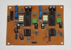 you've got a lot on ebay https://www.ebay.com/sch/i.html?_from=R40&_trksid=m570.l1313&_nkw=ELEKTRONIKA+MK+44&_sacat=0 Thx for the explanation :) fun project! Best
 -
dipCoreF4 and dipBoardF4, a compact Core.
Antichambre replied to Antichambre's topic in Design Concepts
Hello good Sunday, Here it's raining a lot, I've got nothing to do outside... Then I completed the BOMs: BOM for dipCoreF4 BOM for dipBoardF4 BOM for USB module BOM for External Power module BOM for SD Card module BOM for MCAN module Note to the beta testers: The 8MHz Quartz is not easy to find in this package(proprietary one), but I ordered some and I will put enough for you in the envelope. Think about the IDC micromatch male connectors for your ribbons, I just listed the female sockets ;) Best Bruno -
CEM3379 Stereo VCF assembled board
Antichambre commented on Schrabikus's gallery image in Schematics and PCBs
Great work! Funny; someone here talked about the CEM3396, then nothing... And without a word you come with the CEM3379, board already done! That's cool. Did you plan to connect it to a Core? Did you think about a front panel? Doku? -
You can maybe find here some idea to get a non-linear response and signed/unsigned conversion.