

Hawkeye
-
Posts
3,636 -
Joined
-
Last visited
-
Days Won
36
Content Type
Profiles
Forums
Blogs
Gallery
Everything posted by Hawkeye
-
Hi Altitude, yes, if I remember right, the display is initialized in 8-bit mode - commenting out this part could work - but it is highly experimental - you´d also need to connect the other four data wires, and change something on the MB6582 baseboard as well... I think someone around here has an OLED running in 8-bit mode - would be best to get his driver and instructions on how to connect everything... Regarding the NOPs - yes, i remember - as it was timing critical, i added those - afterwards the display worked. You could try with more or less NOPs - but again, highly experimental... If nothing works, and you´ve also got an 8-bit core lying around and have some time at hands - i´d give it a go - have to visit customs from time to time anyways. But the cost will be prohibitively high (shipping alone) - If you really want to do it, please declare as a Gift, 10$ value on the package and write me an email saying, that you want to get rid of this old electronics stuff and that I should take it as a present - the customs guys (although they grumble a lot) sometimes accept it like this, especially if there is wires hanging out and it is looking like a movie prop from "Back to the Future" :-). Many greets and good luck! Peter
-
Building a MIDIbox SEQ V4 (Wilba Control Surface) - Photo Tutorial
Hawkeye replied to Hawkeye's topic in Tips & Tricks
Thx, man! :-) Yes, you´re right, it is very relaxing! :-). No hurries regarding the sketches, still waiting on a few small parts from Reichelt... Many greets! Peter -
Argh, it´s always the same with these things! :-) As far as I can remember, the problem was entirely timing-related. So a few NOPs (or removal of them) here and there solved it - I think. Another idea would be to try and use 8-bit mode (see all those recent OLED threads and success stories). (In 4-bit mode, the open pins were not a problem for my VFD, but I don´t have much EE knowledge, you could try to ground them) If you´d live next door, i´d love to step in for some old school driver hacking session, but as it is now, I don´t have a spare 8bit core (will not touch the MB6582, it is essential for life :-)), and what´s even worse - customs will intercept your parcel, resulting in 2 hours of drive+wait+explanations what that scary bit of wire spaghetti inside the parcel is doing and why i receive that from the U.S. from a private sender and what the "real" price is... oh, i don´t like them, did I ever tell that story? :-). You´ll solve it, just be persistent! :-) Many greets, Peter
-
Building a MIDIbox SEQ V4 (Wilba Control Surface) - Photo Tutorial
Hawkeye replied to Hawkeye's topic in Tips & Tricks
Step 5: Caps, Sockets and Resistors Parts Used: * 8 pcs small 100N capacitors http://www.reichelt.de/Multi-Layer-Leaded-Z5U-20-/Z5U-5-100N/3//index.html?ACTION=3&GROUPID=3163&ARTICLE=22986 * 8 pcs 16 pin dual inline sockets http://www.reichelt.de/Sockets-IC/GS-16/3//index.html?ACTION=3&GROUPID=3215&ARTICLE=8208 * 12 pcs 220R resistors (matching your LEDs) http://www.reichelt.de/1-4W-5-100-Ohm-910-Ohm/1-4W-220/3//index.html?ACTION=3&GROUPID=3064&ARTICLE=1382 Description: * Let´s place and solder the LED brightness- (and current-) controlling resistors first. You might need to employ different resistor values, if you use different LEDs - but for the Kingbright DuoColor LEDs we are about to use, these values work fine. * Drop and solder the resistors in the center area of the PCB in the slots named R1-R8A: R1 220 Ohm bicolor LED (green) R2 220 Ohm bicolor LED (red) R3 220 Ohm bicolor LED (green) R4 220 Ohm bicolor LED (red) R5 220 Ohm single color LEDs, left side R5A 220 Ohm single color LEDs, right side R6 220 Ohm single color LEDs, left side R6A 220 Ohm single color LEDs, right side R7 220 Ohm single color LEDs, left side R7A 220 Ohm “Beat†LED and J3:1 (cathode=J3:2) R8 220 Ohm single color LEDs, left side R8A 220 Ohm unused LED at J3:3 (cathode=J3:2) * Ready? See Photo 1 for comparison - note, that R5A and R6A are not in this photo - they are a few centimeters to the right! * Let´s continue with the shift register IC sockets and the capacitors, which are located within these sockets. It is important to get very small 100N caps, so that they can fit within the tight space (photo 2 shows how it could look like, when finished). * Insert the eight shift register 16-pin sockets first (make sure you align the socket notches to the PCB-printed notches - so you later know how to align the shift registers), then turn over the PCB and solder 8x16 pins (photo 3). * Then drop the capacitors, potentially bending them, so they fit inside. See photo 4 for a bending trick to fit 2.5mm capacitors into the 5mm spaced holes. * Fix the capacitors with tape - turn the PCB over and solder - done (photo 5). Congratulations! You´ve just soldered the foundation for the shift register input and output matrices of your SEQ V4 control surface - these will accept tactile switch presses and encoder events, as well as drive all LEDs later on.


-
Building a MIDIbox SEQ V4 (Wilba Control Surface) - Photo Tutorial
Hawkeye replied to Hawkeye's topic in Tips & Tricks
Step 4: Diode Droptime! :-) Parts Used: * MBSEQ V4 Control Surface PCB from SmashTVs MIDIbox shop (SEQ CS PCB): http://www.midibox-shop.com/buy.html * 58x 1N4148 Diodes: http://www.reichelt.de/Diodes-1N-UF-AA-/1N-4148/3//index.html?ACTION=3&GROUPID=2987&ARTICLE=1730&SEARCH=1n4148&SHOW=1&OFFSET=16 Description: * In this step, we will begin to work on the SEQ control surface PCB - photo 1. * Let´s start with the tiniest components, the diodes. Soldering from small to large parts will make the assembly process a bit easier. * Pre-bend the diodes and drop them aligning the "marked end" of the diode with the dotted mark on the PCB (photo 2). * To simplify the component dropping process, you can lift the PCB by a few centimeters by placing it on "spacer objects", like books. * After dropping, you can fix the components with a bit of packaging tape on the topside of the PCB (photo 3). * Check the diode mark alignements one more time, then turn over the board, and cut the pins (photo 4). * Then solder, slowly counting to 116 :smile:. After you´ve reached that number, you can be certain, that you´ve soldered every connection. * Photo 5 shows all diodes installed and soldered. Note: * As my friend jojjelito noted, a cool speed-up-trick with through-plated holes is to just top-solder on the "elevated pcb" - you can then skip the fix-with-tape step completely - and cut off pin remains on the backside of the PCB after soldering. Cool trick! :-)


-
Building a MIDIbox SEQ V4 (Wilba Control Surface) - Photo Tutorial
Hawkeye replied to Hawkeye's topic in Tips & Tricks
Thanks, TK.! :-) Step 3: Displays FTW! Parts Used: * 2x 40x2 LCD (HD44780 compatible), e.g. the ones below, but buying off ebay is cheaper! http://www.reichelt.de/Hintergrund-blau/LCD-402A-BL/3//index.html?ACTION=3&GROUPID=3006&ARTICLE=53953 * 16 pin flat ribbon wire, e.g. http://www.reichelt.de/Flachbandkabel/AWG-28-16G-10M/3//index.html?ACTION=3&GROUPID=3328&ARTICLE=47655 * 4 pcs 16 pin crimpable IDC socket: http://www.reichelt.de/Pfosten-Wannenstecker/PFL-16/3//index.html?ACTION=3&GROUPID=3231&ARTICLE=14573 * 2 pcs 16 pin dual inline pin headers: http://www.reichelt.de/Strip-Connectors/SL-2X50G-2-54/3//index.html?ACTION=3&GROUPID=3220&ARTICLE=19500 (one item is enough, cut it with a sharp knife) Description: * Starting with displays is always a good idea, regardless of the MIDIbox project! This allows you to see what is going on, have a glimpse on the UI, before the unit is finished, and simplifies testing newly added compontents. * Ready your displays and cut two 2x8 pin headers with a sharp knife (photo 1). * Solder the pin headers to the backside of the displays (photo 2). * Prepare two display cables with 16-pin IDC connectors on both ends, as shown in photo 3. For this project, I´ve made some extra-long display cables, to allow flexible placement of the Core - don´t know how the case is going to look, yet :smile: - Normally, you can use shorter cables. * Connect and test everything as shown in photo 4. Easy and very gratifying to see the startup screens of your new SEQ! :-)


-
Building a MIDIbox SEQ V4 (Wilba Control Surface) - Photo Tutorial
Hawkeye replied to Hawkeye's topic in Tips & Tricks
Hola, Here you go: PDF Plans for the Control Surface CS: http://www.midibox.org/dokuwiki/lib/exe/fetch.php?media=wilba_mb_seq:wilba_mbseq_pcb.pdf http://www.midibox.org/dokuwiki/lib/exe/fetch.php?media=wilba_mb_seq:wilba_mbseq_pcb_dimensioned.pdf And DXFs: http://www.midibox.org/dokuwiki/lib/exe/fetch.php?media=wilba_mb_seq:wilba_mbseq_dxf.zip The LED size (seen from top) is 5mm (wide) x 2mm (high) Regarding LED vertical alignment, I´ve attached a picture showing the vertical measurements of your board! :smile: Your frontpanel can be elevated with spacers to 8mm above the PCB, and be 2mm thick - so that its upper edge is flush with the LEDs (at 10mm), and the tactile switch buttons and the encoder shafts emerge above it. Then your frontpanel would need cutouts for * the LEDs (cutout bigger than 5x2mm! Recommend 6x3mm or else they will be *very* difficult to insert, there are >40 of them! :smile:) Within small limits, you can bend the LEDs in place, so maybe you could get away with 5.5 x 2.5mm cutouts, when even smaller, it might get difficult to attach the frontpanel without stress and an extra dose of caffeine :-). Please note, that the assembly is not done by an industrial robot, so there are tolerances :smile:. * the encoder shafts (diameter 6mm, make the cutout hole 9mm, the knob will cover it) * the tactile switch buttons (which are 12x6mm - recommend the cutout to be 13x7). --- Edit: another (quite cool) alternative would be to use transparent (e.g. black smoked) acrylics and to not cut out the LEDs (but let them shine through the acrylics), In this case, you´d need to just cut out for the encoder shafts and the tactile switch buttons - this would also reduce cost a bit! You could then mount the acrylics panel on 10mm spacers, and lift the encoder buttons a bit (to 14mm would be possible), so a 3mm thick acrylics panel would work. In hindsight (and for uniqueness reasons), i´d recommend to go for this method - there are already so many aluminum panels out there :smile: Many greets! Peter
-
Building a MIDIbox SEQ V4 (Wilba Control Surface) - Photo Tutorial
Hawkeye replied to Hawkeye's topic in Tips & Tricks
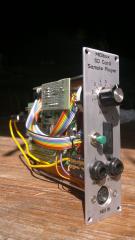
Step 2: No Tape Drive found? Use SD Storage! Parts Used: * SD Card Adapter, e.g. harvested from a CHEAP USB-SD Reader: http://www.reichelt.de/Card-Reader-and-Adapters/CARDREADER-SD/3//index.html?ACTION=3&GROUPID=5262&ARTICLE=144560 * 10-pin flat ribbon cable: http://www.reichelt.de/Flat-Ribbon-Cables/AWG-28-10F-3M/3//index.html?ACTION=3&GROUPID=3328&ARTICLE=47668 * 10-pin crimpable IDC socket: http://www.reichelt.de/Header-and-Tray-Plugs/PFL-10/3//index.html?ACTION=3&GROUPID=3231&ARTICLE=14571 Description: * Search the 10-pin J16 socket on your Core board - this will be our interface to the SD card. * Obtain a SD socket/card adapter - a respected method is by ripping apart one of those cheap SD card readers (~1.45€) and desoldering it. * Crimp the IDC socket to the 10-pin ribbon wire - here is a description how to crimp these: * Study the MBHP_SDCARD schematics: http://ucapps.de/mbhp/mbhp_sdcard.pdf * Following the schematics, wire every ribbon wire cable to the appropriate SD card adapter pin - end result: photo 1. * Connect the SD card adapter to your core (J16) - photo 2. * You now have the possibility to store your SEQV4 hardware configuration, your sequencer sessions, MIDI Files, SYSEX dumps and a very secret copy of your personal diaries on your MBSEQ! :-) * Using a computer, and another (still operational :-)) SDcard reader, format a SD card with the FAT32 filesystem. * For the beginning, just copy the file MBSEQ_HW.V4, which is located in the downloaded zip from Step 1 in the hwconfig/wilba directory to the root directory of your SD card. * Remove the SD card from your computer and insert it into your new SD card adapter already attached to your core. * In the (still running) MIOS Studio terminal, you should see a message "SD Card connected, loading session DEFAULT" * Now type "sdcard" in the MIOS Studio terminal command line - the MBSEQ app will now dump a few SD card specific information items. The last line should say: "File /MBSEQ_HW.V4: valid" - photo 3 * Congratulations! You now have a working storage subsystem on your SEQ! Also, the base configuration file is present (and has been recognized by the MBSEQ). This configuration file is used to determine the frontpanel hardware characteristics (LEDs, tactile switches, encoder placement, ...) of your frontpanel. Fortunately, it has been standardized for Wilbas frontpanel and there is nothing much left to do. * Grab a cold beverage and enjoy! :-) Edit: brackets - please do upload any 3D sketches + designs! Am interested! :-) But before going into exact work, I would recommend to wait until the final unit is ready - so you can take exact measurements! :-)


-
... in a MB6582? Got one running (and loving it!), but had to hack the assembly, and it has been a few years! :-) You can have the .hex, if I can find it! :-) Edit: moar info here: Edit2: you should be able to get it up and running by replacing the app_lcd.inc, then recompiling: Edit3: and please replace the .hex only on the display core - it will crash on the others :-D Best of luck! Many greets, Peter
-
Building a MIDIbox SEQ V4 (Wilba Control Surface) - Photo Tutorial
Hawkeye replied to Hawkeye's topic in Tips & Tricks
Step 1: Core Works Parts Used: * MBHP Core LPC17 Module * USB Cable * A computer with a running version of MIOS Studio Description: * Build the core following the very detailed description on ucapps.de: http://ucapps.de/mbhp_core_lpc17.html (photo 1) * Alternatively, you can use an old STM32 (version 1 Core32) board and refer to the photo tutorial linked here: Note: this core is deprecated and should only be built, if you have old STM32 boards in stock. (Despite it being deprecated, many people still use it in their MBSEQ V4 units - and they work perfectly! :smile:) * Another alternative is the very new STM32F4 Core, described here: http://ucapps.de/mbhp_core_stm32f4.html * After assembling the Core (and writing the MIOS32 Bootloader, as described on the construction page), attach a USB cable and launch MIOS Studio. Select the MIOS32 MIDI IN and MIDI OUT interfaces as MIDI IN and OUT Interfaces, respectively (photo 2) - the MIDI interfaces can have slightly different names depending on your operating system, core board version, bootloader and MIDI drivers :-). Just use the new MIDI devices, that appeared, after you plugged in the USB cable :smile:. * Now download the newest version of MIDIBOX SEQ V4 for your core from http://ucapps.de/mios32_download.html TK. releases compiled versions ready for installing to all different (and supported) Core boards - which is very nice, so we mere mortals do not need to compile ourselves :-)). For this build, we used http://ucapps.de/mios32/midibox_seq_v4_083.zip MIDIbox SEQ V4 Version 83, which is the current version close to Midsummer 2014! :smile: * After downloading, unpack the .zip, and within MIOS Studio click "Browse" and select the .hex file you just extracted from the directory matching your core architecture (here: from the directory MBHP_CORE_LPC17). After a few seconds, MIOS Studio will be ready to upload (photo 3). * Press "Start" to upload - after the upload, you´ll get a nice green message, that the upload was successful (photo 4). * Congratulations, you´ve just installed the MBSEQ V4 app on your Core (in the console window of photo 4, you´ll see the version number)!


-
Hola, it has been a while since the last photo tutorials - I really wanted to do this for some time, but there was always work or some other distraction... but now, there is some time to spend at the solder station :smile:. This will be a documented one-time build for a MIDIbox member, who is an industrial designer and wants to create his own MBSEQ enclosure and frontpanel (thus the non-standard control surface LEDs). Am very eager to see the end result :-). Each step will be photo-documented and contain parts lists, where possible - hope you enjoy the build documentation and that it may be some help to other people wanting to build a MBSEQ, who may yet be intimidated by the amount of parts necessary, the soldering or the software configuration. I will try to structure this tutorial in such a way, that progress is quickly visible - and that you do not need to assemble everything before "turning it on" the first time. The faster some progress is visible, the higher the motivation to continue building... :-) The MBSEQ is the most awesome piece of music gear, that I own - many thanks to TK. and Wilba, who made it possible! Enough talk, let´s get started :-) Many greets, Peter Here are links to other existing photo tutorials: Custom SEQ V4 (DIY control surface, VFDs, ebony wood carrier): MB6582 Control Surface:
-
Hola, Will do a bit of MIDIbox soldering (and photo documentation :-)) in the next time, so I thought I´d share a small tip upfront... If you were ever soldering, you probably also experienced Murphys Law, stating that solder fumes, that rise up, are always going to fly directly into your eyes, nose, mouth or other facial parts :-). Was annoyed because of this and had a look around on Reichelt, looking for Solder Fume extractors. I found some in the price range of 30€ - 900€s... The most important part of these were the carbon filters, that will (to a certain extent) bind the solder fumes... You can also buy those filters as spares directly for only ~ 5€... http://www.reichelt.de/Fume-Extraction/FILTER-426-3/3//index.html?ACTION=3&GROUPID=4135&ARTICLE=87380&SHOW=1&OFFSET=500& And if you have any old 120mm PC fan and a 12V power suppy at hand, you are in luck, because it is really easy to build your own fume extractor from these parts - which of course does not meet any industry workplace safety requirements, but will keep those solder fumes out of your face :-). For this project, I strapped two of those filters behind the old PC fan with rubber bands - works nicely and also cleans the air from old pizza scents... :smile:. Further DIY tuning is possible - you could integrate a LED solder-area-lighting, improve the air intake, or build a better footstand (elevate the fan a little bit to improve efficiency). For now, it works well for me - let me know what you think - or post pictures of your own DIY solder fume extractors :-) Hope you enjoyed this quick tip - happy soldering, everyone! Peter


-
Fully agreed! Just wanted to point out the advantages of pushing-the-same-encoder-to-accellerate input, especially if you are busy knobfiddling somewhere else with your other hand. But i also would not replace already working (non pushable) encoders for that, but maybe if someone plans a new build he/she gives it a thought! :) Many greets, Peter
-
Sorry for the late update :smile: Pushable encoders, that do speed up the current encoder data input (when pushed) are awesome! First experienced it on the Elektron MD... it is also supported by MBSEQ V4 via FAST2 (in mbseq_hw.v4). When you get used to it, you don´t want to miss that feature anymore :smile: as you basically have two encoders at your disposal - a standard one with 24 "clicks" per turn (for fine trimming) and one with the equivalent of e.g. 120 "clicks" per turn (for fast parameter changes), when the speedup-factor is 5 for example. Many greets, Peter
-
As ilmenator said - all is good! It can sometimes take a little bit, as Tim is preparing and shipping lots and lots of packages.... You can also take a look at http://www.midibox-shop.com/status.html , which shows which orders are being processed (but that page may also take a few days to get updated). Many greets, Peter
-
Very cool project! Just not there with enough legacy synths to need it yet, but good to know, when G.A.S. strikes again! :) Many greets! Peter
-
Hi Joan, Welcome to MIDIbox! I have all the parts for another SEQ V4 (without case and frontpanel), but have not had the time/incentive to build it yet - my first one is going strong, it is awesome, and I don´t think, i will need the second one. PM me, if you´re interested in the exchange for the OP-1, but I think the deal is bad for you, as the SEQ parts are much cheaper :-). You could solder it all by yourself, will only take a few evenings... and that would be the spirit of MIDIbox - learn and enjoy, what you´ve accomplished... :-) Many greets, Peter
-
Live input from Different Channels for Different Tracks
Hawkeye replied to phillwilson's topic in MIDIbox SEQ
Hola! Yes, MIDI router FTW! You can route (and duplicate) anything coming from any MIDI IN Port (up to 4) / Channel (single selection or all) to any MIDI OUT PORT (up to 8)/Channel - that alone makes the SEQ awesome! :smile: Regarding your usecase: you could route from MIDI IN 1, different MIDI channels to MIDI OUT 1, different MIDI channels - currently, up to 16 routes are possible. Many greets and have a great weekend! Peter -
Sounds very nice! Many greets from a fellow MB6582 user :-) Many greets, Peter
-
Alpha Encoders – are they cheap rubbish? (MB6582)
Hawkeye replied to punkdISCO's topic in MIDIbox SID
Hi Blatboy, <offtopic>Good to hear from you - many greets to NYC!</offtopic> Regarding the alpha encoders - hm, mine still rock the house, but am beginning to wonder, if there have been a few bad batches lately :smile:. If you have not sealed them up, you could try opening them, and bending the metal lip upwards (towards the encoder wheel) - this should improve contact - i did it with mine after removing the detentions. Many greets, Peter -
Thanks, J! :-) Many greets up north! Bye, Peter
-
Thanks, ilmenator! :smile: Have a great weekend! Peter
-
Hola, just in time for the weekend, a new live MBSEQ V4 session and a multicolor vector voyage! :-D http://youtu.be/c1HnoE4Rh5I Hope you enjoy and thanks for watching and listening! Peter
-
There i finished it :) was a great feeling
Hawkeye commented on GMAprogrammer's gallery image in Members Gallery
 Awesome job! :-)
 -
 Great work! :)


