

jjonas
-
Posts
422 -
Joined
-
Last visited
-
Days Won
24
Content Type
Profiles
Forums
Blogs
Gallery
Everything posted by jjonas
-
From the album: miscellaneous
-
From the album: miscellaneous
-
From the album: miscellaneous
-
Hi, I uploaded accidentally the same image twice, but I couldn't find where I could delete the extra one. When selecting the image in one of my albums, "Manage image" allows me only to "Edit details", but options there don't include deleting the image.
-
From the album: miscellaneous
-

From the album: miscellaneous
-
From the album: miscellaneous
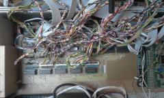
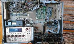
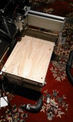
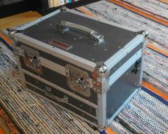
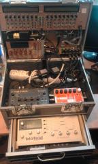
Sequencer box built inside a cheap Wisent tool box (from a recycling center). Contents: MBSEQv4, MBSIDv2 (with noise gate and SSM2044 filters), two sample players (one for mellotron and drum samples, another one for the drummer's tempo track), DSI Tetra, EHX V256 vocoder, Waldorf Blofeld, 2x Behringer MX400 mixers. -
Also it would be good if Phrase mode / Song mode status was saved with each session. Once you have a finished song structure for band rehearsals or live performance, you still have to switch the Song mode on manually (Phrase mode is the default). EDIT: Phrase mode is not the default, instead the current Song/Phrase mode setting is carried over across sessions. Phrase mode is ok as default for a new session, but I think it would be handier if Song/Phrase mode setting wasn't global but session based.
-

"oscillators are not completely silent once a note has been played"
jjonas replied to fallenturtle's topic in MIDIbox SID
If you have a stereo MBSID, see this thread for a DIY stereo noise gate solution: -
I have a few ensembles, but most of the time I use E002 with pretty straightforward settings. The other ensembles that I have contain keyboard split zone settings (in the INS submenu), either for "normal" lead patches (each zone playing instrument 1 on up to four different MIDI channels, i.e. one channel per core), or for multi patches (up to 6 instruments on different zones of the keyboard). Also it can be useful to check whether you want your multi, drum and bassline patches playing mono (set in the SID submenu), unless you can address the (possibly inconvenient) hard left/right pan issue in your mixer (by setting separate left and right channel inputs to the middle). The latter solution is better, because in mono mode you "lose" half of the oscillators (because each stereo pair now plays the same sound).
-
Just a thought: are you on Windows or some Linux distro? I've had problems with MIOS Studio detecting the PIC with bootloader when on Linux (it seems random), but on Windows it's worked ok.
-
I used JST XH crimp terminals. The "official" JST crimp tool is indeed expensive (200-300€ or more), but after writing in the thread jaytee referred I did find a tool that works with the JST XH terminals, and cost only £20 (from a UK seller). The tool is called "SN-01BM". Naturally it's not as good as the official JST crimp tool; for example the crimps get a bit stuck in the jaws after crimping, and you have to use a bit of force to pull them out, while with the official JST tool they just fall out. Likewise the crimped terminals' fit into the housings is not as perfect as with the official tool. But in my estimate the cheap too is good enough. JST XH crimp terminals and housings are available on eBay.
-
Did you see Section 6.1. and its subsection, 6.1.6. (Sending internal CCs over a bus to control track settings) in the Beginner's Guide?
-
Midibox SID: Simple Control Surface and LCD wiring questions
jjonas replied to fallenturtle's topic in MIDIbox SID
LCD wiring: I've done both option that you mention (cut, resolder, shrink tube, or adaptor), both work. None of them have failed me over the years, but I kind of think the adaptor board is more transparent when troubleshooting. I've found that soldered ribbon cable connection can break if there's too much movement. Well that's like any soldered connection, but because the gauge is so small it's more vulnerable. With an adapter board + wires you can see if a wire has broken off, but with the connections inside shrink tube you have to use a multimeter to beep every wire. I would probably make an adaptor from a simple strip board if I have the space for it (solder on a 2x8 pin header, cut the strips in between the header length-wise and then reconnect with air wires). The last time I did it I didn't have the space, so I did the cut-resolder-shrinktube. In the end it is probably not that significant though. Buttons: When I did my own control surface years ago, I chained the grounds of the buttons/encoders/LEDs that were near each other. In principle you could take just one GND from a DIN or DOUT board and then just chain everything from that point. Primarily it's a matter of your control surface design I guess. This applies to the "best way" of wiring the buttons as well. If you found the designations in the code, you can probably change them to your liking pretty easily. Just keep in mind that encoders are always assigned to two pins so that the pin designation (designating the first pin of the pair) is always 0, 2, 4, or 6. Designation "0" takes pins 0 and 1, "2" takes 2 and 3 etc. "3" doesn't assign pins 3 and 4, it just won't work. MIDI IN needs only two wires (pins 4 and 5). I don't think ribbon cable gauge will have a negative effect on the MIDI signal. Audio: I've used 0,25qmm wire or smaller gauge (no shield), I've never had any problems that I can hear. -
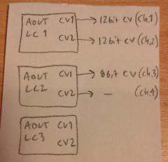
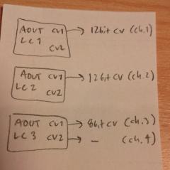
Hi, I've built an MBSID with a single SID chip in it, and I'd like to add an SSM2044 filter to it. So I need two channels: one for cutoff, one for resonance. In the MBSID sources (setup_8580.asm) there's the choice between three different resolution options: ;; only relevant if one or more AOUT_LC modules are used: ;; define the resolution configuration here ;; 0: first channel 12bit, second channel 4bit ;; 1: first channel 8bit, second channel 8bit ;; 2: combines M1,M2 and/or M3/M4: first channel 12bit, second channel 12bit, third channel 8bit, fourth channel ignored! ;; all other values invalid! #define AOUT_LC_RESOLUTION_OPTION_M1 0 #define AOUT_LC_RESOLUTION_OPTION_M2 0 #define AOUT_LC_RESOLUTION_OPTION_M3 0 #define AOUT_LC_RESOLUTION_OPTION_M4 0 I'm interested in the third option, as it would give me 12bit cutoff and 12bit resonance CVs. But I'm not sure that I've understood it correctly, as option 2 is not described on the info page on the AOUT-LC module (or the MBSID CV options page). With options 0 and 1, the first LC module provides channels 1 and 2, the second LC module provides channels 3 and 4, and so on. Ok. So each board provides two CV outs, either 12 and 4 bit ones, or two 8 bit ones. But with option 2, which CV outputs on which modules give out the CVs? 1. Does it mean that the first LC module's first CV out gives a 12bit CV, the first LC module's second CV output gives another 12bit CV out, and then the second board's first CV out gives an 8bit CV out, and the second CV gives out nothing (or nothing useful)? Like so: 2. Or does it mean that the first LC module's first CV out gives a 12bit CV (=channel 1), the second LC module's first CV out gives a 12bit CV (=channel 2), the third LC module's first CV out gives an 8bit CV (channel 3), and the fourth channel (also on the 3rd LC module) doesn't do anything useful. I guess I could also use option 1, and just use channel 1 (12bit) for cutoff and channel 3 (12bit) for resonance, and just leave the 4bit channels (2 and 4) unused? With option 2, should my setup_8580.asm be changed to: #define AOUT_LC_RESOLUTION_OPTION_M1 2 #define AOUT_LC_RESOLUTION_OPTION_M2 0 #define AOUT_LC_RESOLUTION_OPTION_M3 0 #define AOUT_LC_RESOLUTION_OPTION_M4 0 Or should it be: #define AOUT_LC_RESOLUTION_OPTION_M1 2 #define AOUT_LC_RESOLUTION_OPTION_M2 2 #define AOUT_LC_RESOLUTION_OPTION_M3 0 #define AOUT_LC_RESOLUTION_OPTION_M4 0
-
From the album: miscellaneous
-
From the album: miscellaneous
-
I'm not sure if you saw this already and it didn't answer your question, but just in case it's useful: "You can record CC messages live the same way you can record notes. There are two alternative conditions: either the incoming CC message number has to have a dedicated CC parameter layer already, or there is a CC layer that is currently 'off'. For example, an incoming CC#001 will be recorded to the first CC layer where there already are CC#001 messages, or if there is no such layer, the CC#001 message will be recorded into the first free CC layer. If there are no available CC layers, the incoming messages won't be recorded anywhere." (Beginner's Guide, 4.1.4., Live Recording) As to your second question, I'd guess that if your MIDI router settings (see the Guide, Appendix 3) are ok, it makes no difference where the incoming CC is coming from.
-
Hi, in the pdf on the Wilba frontpanel button/LED matrix, the dual-color GPx LEDs are said to be hardcoded into the firmware. But in the said pdf the information on how to wire them is confusing. In the schematic the dual-color LEDs are wired to pins D4-D7, but in the chart next to the schematic they are wired to pins D3-D0. The question is: which version in the linked pdf – schematic or chart – is the one that I should use if I want to make a DIY frontpanel with DIO matrix?
-
In the zip that you downloaded, there's a folder called hwcfg, which in turn has three subfolders: standard_v4, tk, and wilba. If you have the Wilba frontpanel, you should use the MBSEQ_HW.V4 file from the the wilba folder. In that hwcfg file, F3 is set to REC on/off by default. If you're using the hwcfg file from the standard_v4 folder, F3 will be set to Trigger Layer Select by default.
-
Unfortunately I'm not able to help you with the connection problem. But in any case it's not possible to update the firmware with the SD card (it has to go into the core), so someone else must help you find a way to connect to the core.
-
Try this. Download the midibox_seq_v4_091.zip file from the download page, unless you have already done so. The next step depends on which core you have, LPC17 or STM32F4 (see the links for what they look like). I'm not sure what the MBHP_CORE_STM32 (without the "F4" in the end) is, it might be the old PIC based core. If it is, you're unlikely to have it. (EDIT: it's an expired predecessor of the LPC17. In any case, you're unlikely to have it.) In the zip you have downloaded, there's a folder for MBHP_CORE_LPC17 and for MBHP_CORE_STMF4, and each have a file called project.hex in them. Choose the the right folder for your core and upload the project.hex in that folder.
-
It depends on which firmware version you're using, but if you're using the latest (091) and have Wilba's front panel, button F3 should be assigned to be the REC on/off button by default. If it isn't, you can customise the F1-F4 buttons functions quite easily. See the Beginner's Guide, Appendix 1.
-
I have a computerless synth corner built around the MBSEQv4, so the SD card needs to be removable to change the hw settings for example.
-
(EDIT: I've found what I wanted.) If anyone has an MBSEQv4 Lite PCB for sale, I'd be interested. If it's stuffed already, I might still be interested, but it depends on the buttons etc., so please send a pic.
