Search the Community
Showing results for 'STM32F4'.
-
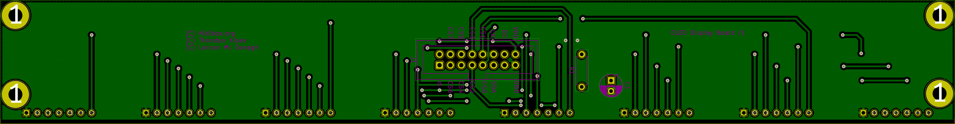
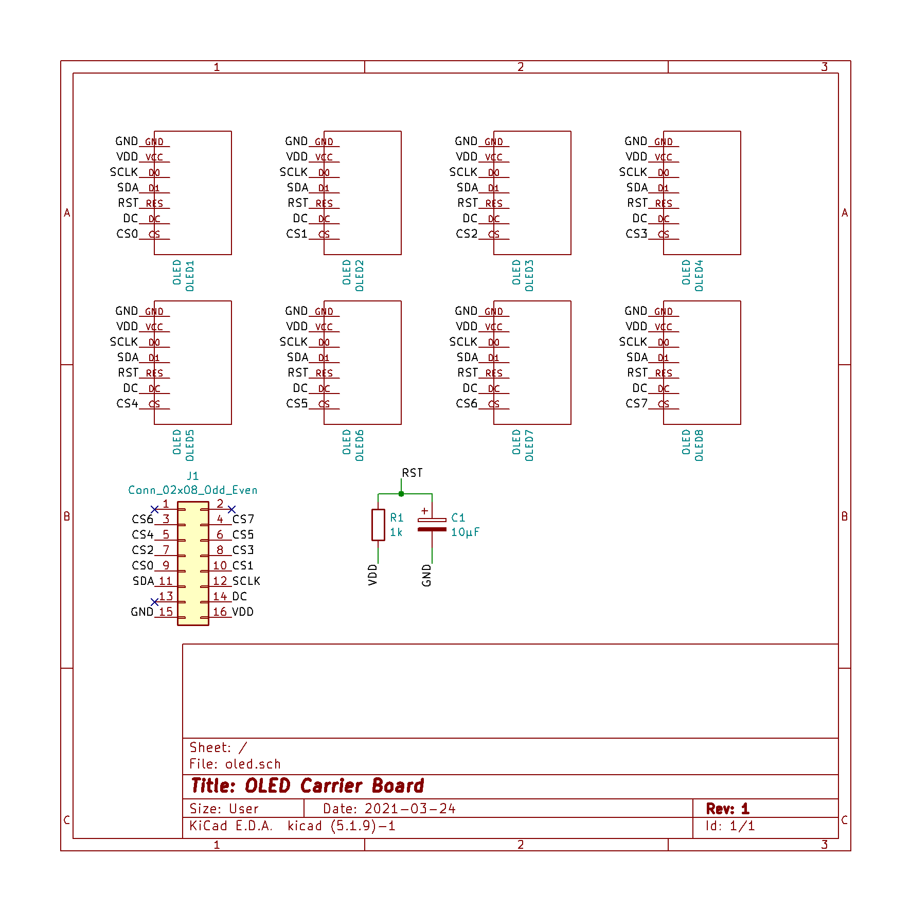
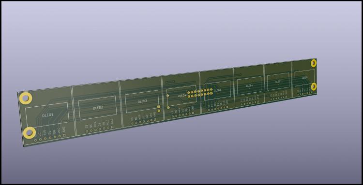
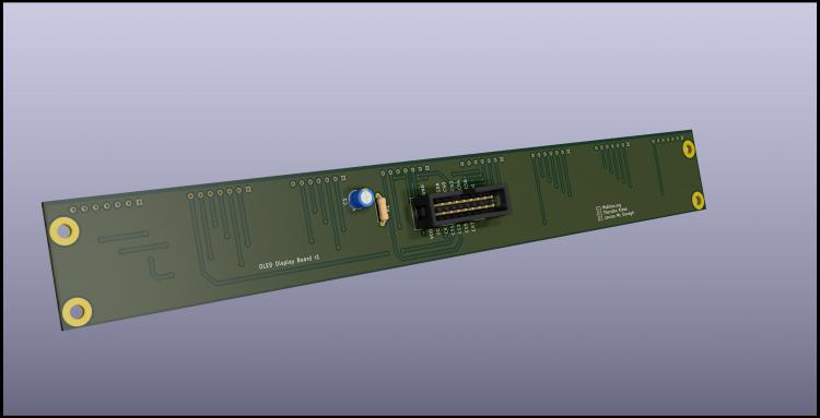
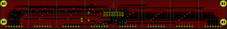
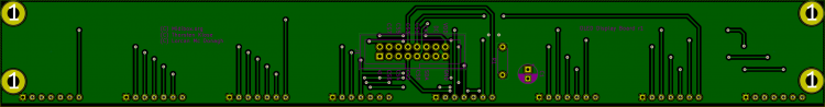
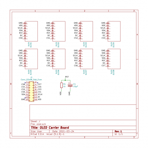
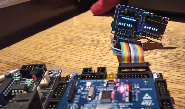
Hi, I'm building a MCU type controller and I'm starting to design some PCB's for the various modules. I'm planning to share them here so other users can use them if they want, if that's ok. The first and simplest one is an 8xOLED carrier board to connect to J15A of the STM32F4 core. Initial tests on a breadboard with 2 screens work fine. It is my first time using Kicad and also designing a 2-layer board, so I'd like to get some feedback before sending them to the fab house. OLED's are 0.96'' SSD1306 4-wire SPI type Mechanically the OLED's are plugged into 1x7 sockets Each 'channel' is exactly 1.1 inch wide. It leaves a little wiggle room between the screens, and should allow the case too be quite compact I remember seeing another schematic with added 100nF decoupling caps, but they're not on Thorsten wiring diagram, so I'm wondering if I should add those NOTE: I'm going to extend the board to avoid having the holes running under the OLED's.
-
Looking at the core schematic, I see CS7 is connected to both Q7 of the 74HC595 and PD7 of the STM32F4, whereas CS0-CS6 are connected only to Q0-Q6 of the 74HC595. If PD7 is also an output pin, I wonder if PD7/Q7 could be interfering with eachother ?
-
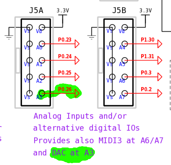
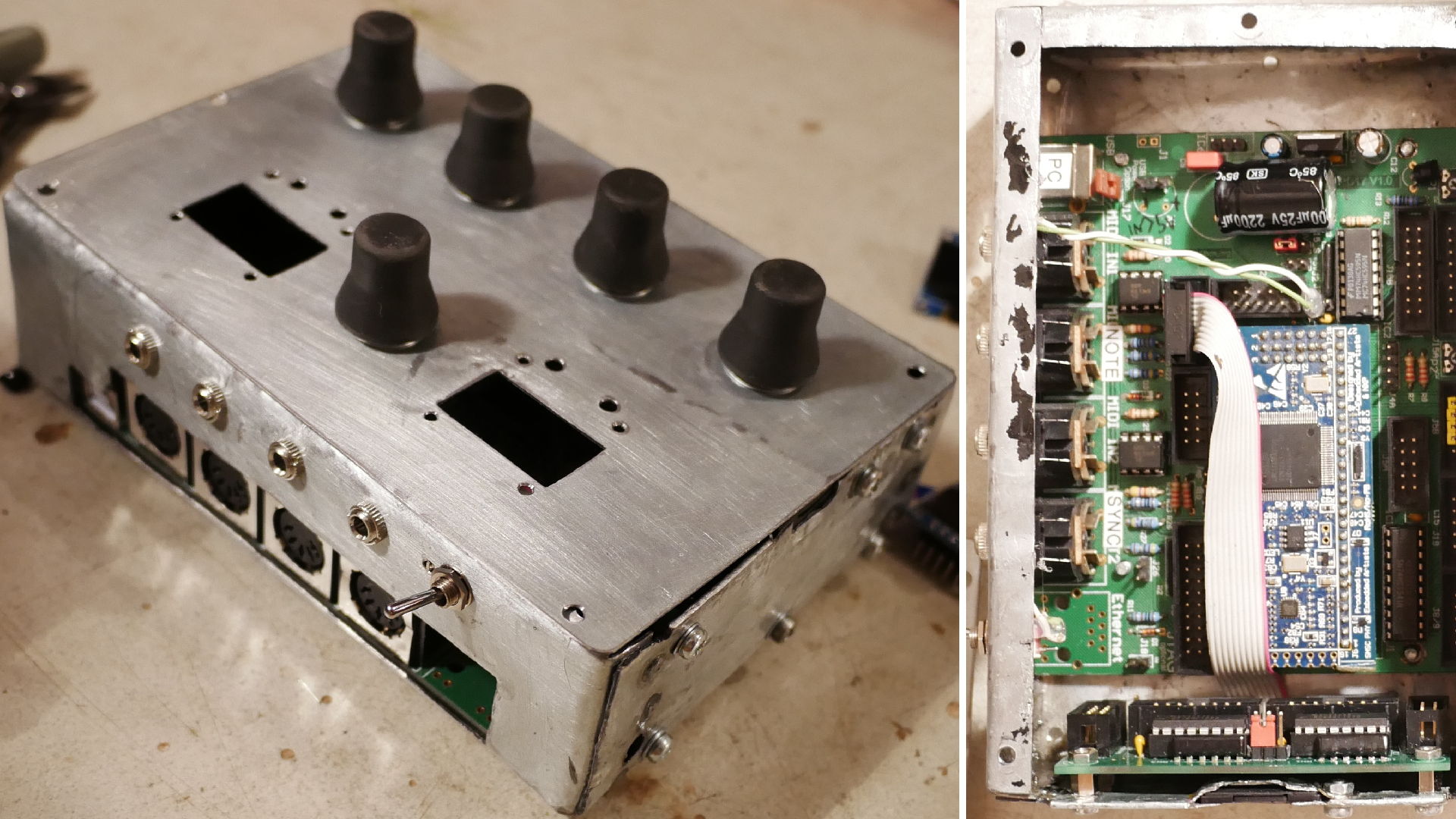
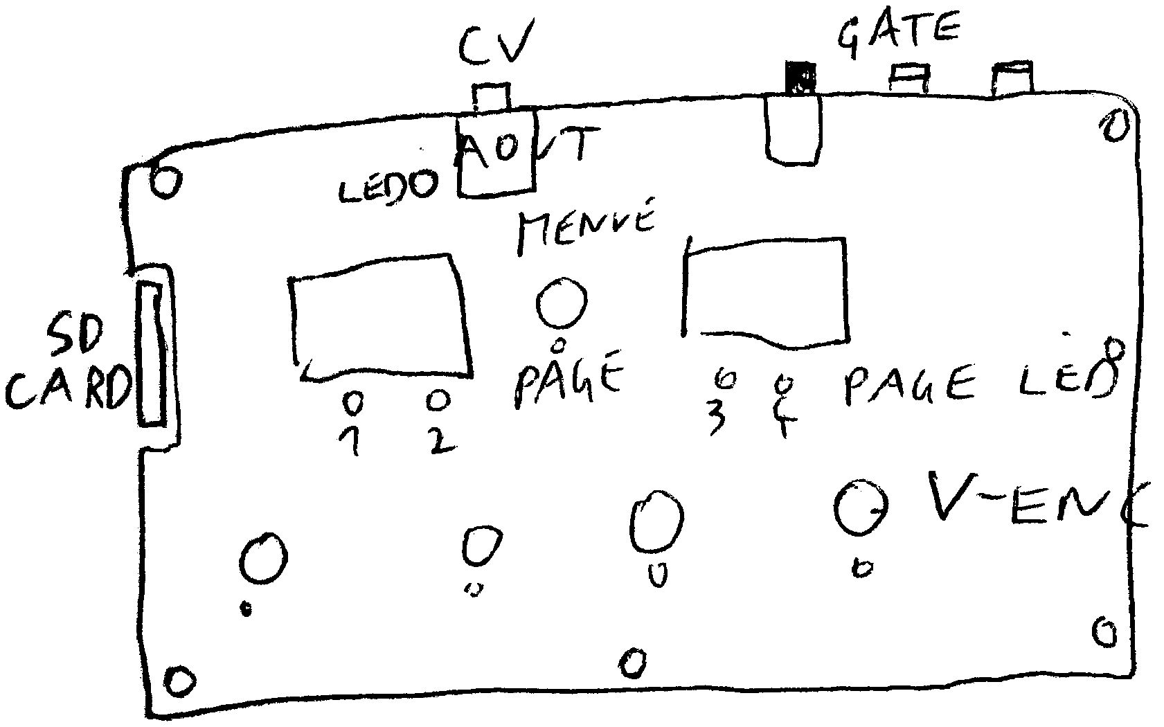
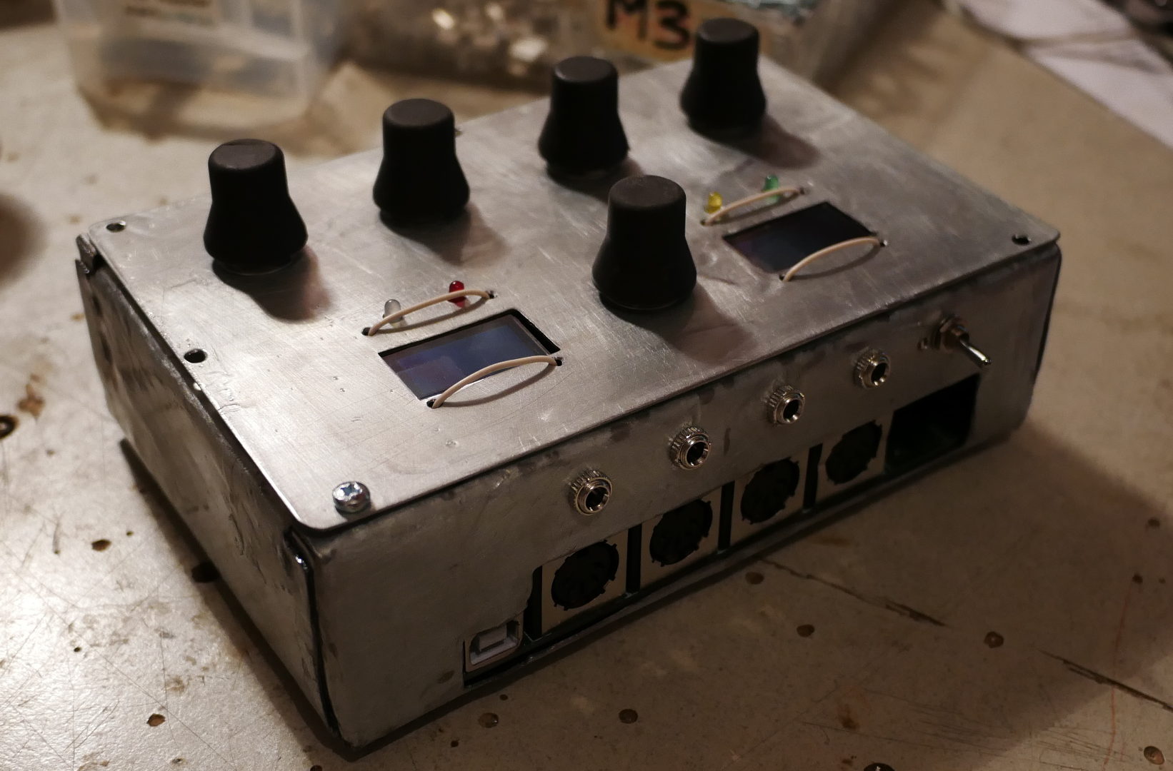
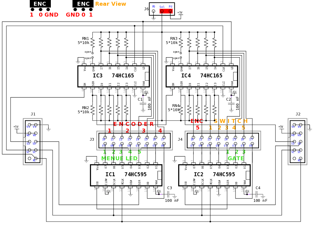
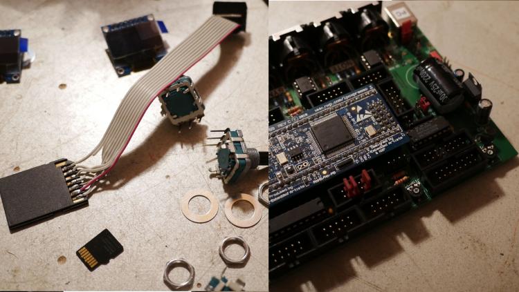
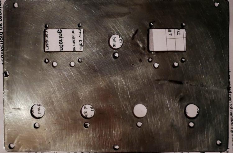
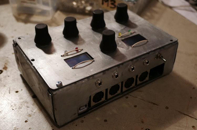
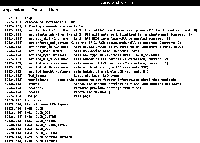
wiki well lets try... I saw on the LPC17 shematic: That on J5A - A3 a DAC is aviable @ I assume 0-3.3V? for CV I need a level shifter to get 0-5V (Analog) >>> I assume OP-AMP will do the job I will use some pins from the DIO-MATRIX as GATES, so i need no Logical Level-Shift - (0V and 5V) Most of UI and the GATES is done by DIO-Matrix: Features (very minimalistic) a ADR and a midiclock-synced-LFO mixed to one CV-Output, 5 Real Encoders (4 Menue Encoders, 1 Menue-Encoder to cycle thru the Pages) 4 Virtuel Encoders on 4 Menu-Pages (= 16 V-Encoders), 4 LEDs to indicate Menue-pages, 4 Encoders / 2 Displays SHOW ing / DO ing: Page 0: ENVELOPE ENCODER 0.A / 10 Switch = curve type 1.D / 11 Switch = curve type 2.R / 12 Switch = curve type 3.+-/ 13 Switch = long/short time Display 1: Scope: ADR - Curve Display 2: Scope: Mixed real CV ADR+LFO Page 1: LFO ENCODER 0.Rate / 10 Switch = ... 1.Wave / 11 Switch = ... 2.x/4 / 12 Switch = ... 3.+- / 13 Switch = ... Display 1: Scope: LFO - Curve Display 2: Scope: Mixed real CV ADR+LFO PAGE 2 MOTION SEQUENCER ENCODER 0.LENGTH / 10 Switch = Activate Motionsequencer 1. / 11 Switch = 2.x/4 / 12 Switch = 3.BPM / 13 Switch = Activate internal MidiClock Display 1: MSQ-Length-Progress Bar + Length in Steps Display 2: Tact System BPM and MasterLoop Progress-Bar Page 3: DISK ENCODER 0.Load Preset Nr / 10 Switch = DO 1.Save Preset Nr / 11 Switch = DO 2.Letter / 12 Switch = Small-Big-Letter 3.Cursor-Position/ 13 Switch = clear Name Display 1: Preset NR Display 2: Preset Name Page 4: SYSTEM ENCODER 0.set MidiCH / 10 Switch = single Channel/all Channels 1.set CV-Trigger-Note / 11 Switch = single note/all notes (automatic assigned to Gate 1) 2.set Gate2-Trigger-Note / 12 Switch = single note/all notes 3.set Gate3-Trigger-Note / 13 Switch = single note/all notes Display 1: Midi Monitor - showing Notes-Nr. and MidiChannel Display 2: Midi Monitor - showing Notes-Nr. and MidiChannel Panel-Layout - and in real world: the case is also "very" diy ;) see the thru Welt-point... @ the moment waiting for M1.6 Screws (a wire holds the displays at the moment)... searching for Level-Shifters.... before compiling the first code i have to set my environment variables from STM32F4: PATH="/home/inet-stick/midibox/gcc-arm-none-eabi/bin:/usr/local/sbin:/usr/local/bin:/usr/sbin:/usr/bin:/sbin:/bin:/usr/games:/usr/local/games:/home/inet-stick/program:/home/inet-stick/Schreibtisch:/home/inet-stick/Schreibtisch/test:/snap/bin" MIOS32_PATH=~/midibox/mios32 MIOS32_BIN_PATH=$MIOS32_PATH/bin MIOS32_GCC_PREFIX=arm-none-eabi MIOS32_FAMILY=STM32F4xx MIOS32_PROCESSOR=STM32F407VG MIOS32_BOARD=MBHP_CORE_STM32F4 MIOS32_LCD=universal to LPC1769 (linux... sudo nemo.... etc/environment... restart linux... have fun doing coding....) PATH="/home/inet-stick/midibox/gcc-arm-none-eabi/bin:/usr/local/sbin:/usr/local/bin:/usr/sbin:/usr/bin:/sbin:/bin:/usr/games:/usr/local/games:/home/inet-stick/program:/home/inet-stick/Schreibtisch:/home/inet-stick/Schreibtisch/test:/snap/bin" MIOS32_PATH=~/midibox/mios32 MIOS32_BIN_PATH=$MIOS32_PATH/bin MIOS32_GCC_PREFIX=arm-none-eabi MIOS32_FAMILY=LPC17xx MIOS32_PROCESSOR=LPC1769 MIOS32_BOARD=MBHP_CORE_LPC17 MIOS32_LCD=universal (the SSD1306 is a "universal") since there was already a mios application in the FLASH, i uplodadet with MiosStudio the actual Bootloader In Mios-Studio - there is the Terminal - where i typed help, and set following: and i noticed that i mounted my G-LCDs 180° wrong... so i choose the ROTATED VARIANT, now its all right... these are all commands: set usb_name CV set lcd_type GLCD_SSD1306_ROTATED set lcd_num_x 2 et lcd_num_y 1 set lcd_width 128 set lcd_height 64 store how ever, num xy and width height will be later overwritten in the app itself....: #define APP_LCD_NUM_Y 1 #define APP_LCD_NUM_X 2 #define APP_LCD_WIDTH 128 #define APP_LCD_HEIGHT 64 #define APP_LCD_LINE_OFFSET 0 #define APP_LCD_COLOUR_DEPTH 1


-

LoopA V2 Introduction, Features & Support Thread
latigid on replied to Hawkeye's topic in MIDIbox User Projects
Were the CN3 jumpers removed from the DISCO board? Otherwise the SWD programmer is connected to two STM32F4 chips. To my knowledge the circuit shown is correct but it has been a few years since I tried it. -
On another note, I looked at current consumptions of various OLED's, and according to this page, a 128x64 0.96” can pull 21mA at max contrast with all pixels lit. As the STM32F4 board docs state, the integrated 3.3V regulator can only supply 100mA max. I wonder if problems some people were having with multiple OLED's might be related to that. So to be on the safe side and to avoid heating the poor little SMD IC, I'm going to add an optional on-board 3.3V regulator or input.
-
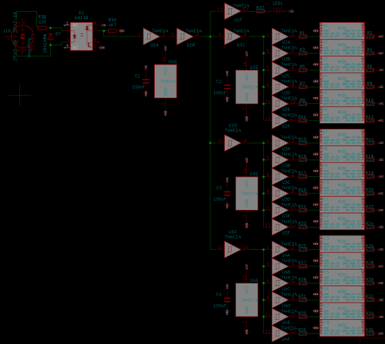
"normally" we use here 7 Pin SPI SSD1306 (GND,VCC,D0,D1,RES,DC,CS) connected like this: purple Lines = CS-Lines: the first (8or?) 16 CS/purple lines you get direct from the Core STM32F4, > http://www.ucapps.de/mbhp_core_stm32f4.html the 48 Rest CS-Lines from 595-Dout-Shiftregistors-Pins (6xICs with each 8 Pins) > we call that http://www.ucapps.de/mbhp_dout.html The Update Rate will be a bit slow - but for Label a static Mixer Desk, it will be ok? custom Bitmaps: http://wiki.midibox.org/doku.php?id=how_to_create_custom_glcd_fonts_icons_bars_for_midibox_ng @ Labelitself, I myself have a simular thing, but for a Midi>CV Device, i have to label Encoders... i managed it to save a huge array of "chars" - like this...: char Label[512][8] = { {'3','0','3',' ',' ',' ',' ',' '}, {'6','0','6',' ',' ',' ',' ',' '}, {'7','0','7',' ',' ',' ',' ',' '}, {'8','0','8',' ',' ',' ',' ',' '}, {'9','0','9',' ',' ',' ',' ',' '}, {'-',' ',' ',' ',' ',' ',' ',' '}, {'*',' ',' ',' ',' ',' ',' ',' '}, {'/',' ',' ',' ',' ',' ',' ',' '}, {'+',' ',' ',' ',' ',' ',' ',' '}, {'A','M','P',' ',' ',' ',' ',' '}, {'A','M','P',' ','E','N','V',' '}, {'A','M','P',' ','L','F','O',' '}, {'A','M','P',' ','M','S','Q',' '}, {'A','D','S','R',' ',' ',' ',' '}, ... with all possible Names - that i could use for Control-Voltage Projects.... i save this on SD-Card, on a .sys file (no PC involved the microcontroller do that) - in a Patch aka Song i then Recall it like this: MIOS32_LCD_DeviceSet( 3 ); // select Display 3 MIOS32_LCD_CursorSet(0, 1); // Select Vertical the second Line, Leftmost Horizontal MIOS32_LCD_PrintFormattedString("%c%c%c%c%c%c%c%c", // 8 Chars is max if you use BIG-FONTS Label[ aout[ENC].sel_label] [0], Label[ aout[ENC].sel_label] [1], Label[ aout[ENC].sel_label] [2], Label[ aout[ENC].sel_label] [3], Label[ aout[ENC].sel_label] [4], Label[ aout[ENC].sel_label] [5], Label[ aout[ENC].sel_label] [6], Label[ aout[ENC].sel_label] [7]); where ENC is the Encoder Number where the LCD is situated. aout[].sel_label: i save that Var on SD-Card-with the Patch / and load the Patch via Midiprogramchange. // with a given Number you adress a Name... you can also custom Labels, with ease with 2 additonal Rotary Encoders (while one is the cursor) (and the other one change the Letter), you might need for a UI-for Midibox at least 3 Encoders(with inbuilt pushbuttons) and 1 SSD1306 in order to SAVE and LOAD or ADD Custom Names...
-
Hi, This does not belong directly to the MIOS, but I haven't found a better sub-forum for my question... I'm trying to learn a lot of the low level stuff associated with MIDI right now. Mostly about USB connection. The svn repo is pretty good for it. I learned a lot of it already... I'm thinking about implementing myself(for learning purposes) a MIDI-USB connection with my STM32f4 dev board. I'm planning to use an ULPI PHY for HiSpeed Connction to achieve lowest latencies(8 times lower latency than FS). I think the Interrupt transfer method should be the best fit for it, since it has guaranteed latency. But now I saw in the svn repo that the MIDI-USB endpoint descriptor uses only bulk as transfer method. Is this just for the compability issue or is it a wrong idea to use the interrupt transfer method, to achieve lowest latencies? Ah just for record, I'm a pretty fussy drummer regarding latencies, since I hear/feel a small difference between 5ms and 10ms(measured and compared by ear...). Best Regards Philipp
-
Hi Frederik, Yes, most ports with specific functions can be used in parallel. J8/9 is for SRIO i.e. input/output shift registers that chain in parallel (DIN/DOUT) J19 is for SPI with two chip selects (AINSER/AOUT) etc. Check the STM32F4 Core details The SRIO chain extends in series parallel, no need for additional Cores generally. Regards, Andy
-
Hi everyone! This is my first post and my first MB project, so I will begin with introducing myself and my project then I will get into my probably simple questions. I was looking for a control surface to use in my home studio that would work with Pro Tools and found that the Avid S3 sells for about $5,000 (USD)! After I stopped laughing/crying, (like always) I looked into DIY options. First I thought of the Arduino solution, but I am awful with programming (no patience for it). I then found midibox and it seemed like the perfect fit! I am experienced with soldering and electronics (from back in the analog days), so I ordered components (Mouser) and PCBs (Modular Addict) and constructed the enclosure. So, long story even longer, here is my goals for the control surface (very simple and basic): 9 channels (probably will expand in the future) Each channel will have: 1 fader (non-motorized for now) 3 buttons (select, record, solo) 3 LEDs (one for each button to indicate toggle state) 1 rotary encoder (not sure for what yet) VU meter for each channel via OLED modules 2 LCD displays (2x40) Keeping very simple for my first build, but I am sure that once this is done, I am going to find quite a few more functions that I want to add. Here is the hardware that I am using: 1-STM32F4 core 1-AINSER64 2-DINx4 1-DOUTx4 It is also based on the MBNG project by TK. So, now that that is out of the way, I have been having some trouble that I am sure it is just me making things harder than they are. I uploaded the MBNG files to the core. I have studied the user manual and wiki very intensively for the past few weeks, but I am not having any luck with any function that I try to program! I started with the "First Steps" section of the user manual (skipped the LCD "hello world" because I don't have my LCDs yet). I put in the code exactly as it is stated, but my button on D0 doesn't send any MIDI message (according to MIOS Studio). Here is the code that I put into "Hello.ngc": RESET_HW LCD "%CHello World!" EVENT_BUTTON id=1 type=NoteOn key=36 I have also tried to get the LED on the DOUT pin D7 to come on when the button next to it is pushed with this: EVENT_BUTTON id=1 fwd_id=LED:1 type=NoteOn key=36 range=0:127 button_mode=Toggle Once again no light and no MIDI event in MIOS Studio. I know that I am probably missing something very basic and I apologize if this question has already been answered a million times, but every thing that I found so far on the forum or wiki has not seemed to make any difference. Also wanted to add that since I am new to forums in general (I'm an old timer), I am sure that I am missing some pertinent information that you guys need to see what is going on, so please let me know and I will do my best to help you help me! Thank you for all your help! videoman199
-
SSl Blog Post 02 Hello again, Last time I wrote about the design process of my console. In this post I want to focus on the electronic part. In the last couple of weeks I searched for the right knobs, faders and pots for the project and I nearly found all I need. The pots were the simplest part. I opted for the Alpha 10k Lin https://www.musikding.de/Alpha-Potentiometer-16mm-10k-lin Each channel will have one motorized fader. Here I choose the PSM01-082A-103B2. https://www.mouser.de/ProductDetail/bourns/psm01-082a-103b2/?qs=MAZTpT1IVl8rvdecO07rRA==&countrycode=DE¤cycode=EUR 14,76€ when I buy more than 25 is a good deal I think. The ones from alps are very pretty, but with prices over 30€ per piece they are quite expensive especially because I need 33. For the bus channels I opted for simple 60mm faders. Also 10k lin, not very investing. https://www.reichelt.de/schiebepotentiometer-stereo-10-kohm-linear-rs60n12-lin10k-p73870.html?&trstct=pol_1&nbc=1 The knobs where a little harder to find. For the Solo Cut and Rec knobs I want to have knobs with Leds which I can connect to an DOUT module separately. So I could press Solo on the console but deactivate it inside my DAW and the LED would follow my actions. After quite a bit of searching and some phone calls with distributors I finally found these. https://de.farnell.com/nidec-copal-electronics/cfpb-1cc-4w9/drucktaster-spst-0-005a-5vdc-panel/dp/3498758 The knobs inside the channel strip are still to be found. The need to be snapaction knobs with a white cap with the measurements of 5mm per side. I couldn’t finde the right ones even after quite some hours of searching. Maybe I’m just searching without the right search terms? Maybe someone of you knows the answer to that problem I didn’t start the search for LEDs just yet. I think and hope these should be easy to find. For the modules I chose STM32F4 for the cores, AINSER 64 for the pots and faders, NG MF for the motorfaders, DIN for the knobs and DOUT for the LEDs. I especially need quite a lot of AINSER modules and I’m still figuring out a way to connect more than two to an STM32F4. I found some blogposts but could get the answer out of these. They suggested it should be even possible to connect more than three? I obviously want to use as less cores as possible. This build will be huge either way. I can connect the MF modules directly to a pc without a pc. Thats what is written on the website. But how do I connect these to the pc? Via midi? There is no USB port on these modules right? And I also should cascade them. I need 5 modules. I want to use 33 motorized faders and that’s quite unfortunate because every mf module only supports 8. How do I cascade these modules? Also via MIDI? The last problem I ran into is the meter bridge. This could be a whole blogpost of its own… My plan was, or partly still is to use 10 7“ displays connected to a 10 times HDMI splitter, which tells the PC there is only one REALLY big screen. But after buying quite some displays to test out I figured out 90% of the screens for sale online are totally crap! Ok, I searched for quite cheep ones, but I need 10 of them and if I had unlimited money I would buy the original ORIGIN console… But I don’t have access to unlimited amounts of cash so I need a cheap display which works. The first one I ordered was the perfect size and easy to operate. But I only could see the image looking from one specific angle. Moving my head just a little bit the whole display would turn blue. The second one was advertised to be 7“, but the one that were delivered to my was only 3,5“…are you kidding me? Out of anger I searched for analog VU meters. I really like the looks of these and figured out these work with voltage. Is it possible to drive VU meters with a midibox module? Maybe with an AOUT module? So many more questions but I already wrote a whole book here…sorry for that. If you still reading in this point thank you very much! Have a nice day! Frederik
-
https://github.com/midibox/mios32/blob/master/mios32/STM32F4xx/mios32_ain.c https://github.com/midibox/mios32/blob/master/modules/ainser/ainser.c https://github.com/midibox/mios32/tree/master/modules/aout Basic drivers/assignments: https://github.com/midibox/mios32/blob/master/mios32/STM32F4xx/mios32_spi.c https://github.com/midibox/mios32/blob/master/mios32/STM32F4xx/mios32_iic.c Maybe it would be easier for you to use the Arduino and output an analogue voltage to be read by the STM32F4 AIN? That way you can use your working system without much extra coding effort. MBIO supports AIN either on the MCU ports J5A/B or using the AINSER module (typically less noise on the signal).
-
As far as I know, there are no I2C peripherals that were coded into MIOS32. The closest thing that I am familiar with is the I2C MIDI modules, that according to TK. were not trivial to code for, and at that on very low-performance 16F PIC chips. All the MBHP framework gives you is a hardware port on the MCU. You could consider to compare your arduino sketch with a device running off an STM32F4 chip or similar. Alternatively, you might find more code examples of SPI devices. Maybe you can try to code a driver for a similar sensor with an SPI interface? The uCapps project is here: http://ucapps.de/midio128.html -- it is more targeted towards general users who would like to use the project without writing code for it. The git project is here: https://github.com/midibox/mios32/tree/master/apps/controllers/midio128_v3 You would need to modify the code to suit your needs. Note that the code is written in C, not python. You can find the documented functions and some examples here: http://www.midibox.org/mios32/manual http://ucapps.de/mios32_c.html Best of luck to you if you decide to follow this journey. Others will probably not write the software for you, but if you post your modifications and explain where you are having difficulty, some might be able to help.
-
I plan to use alpha pots. I got them recommended from a friend. Hopefully they will do a good job. I found an article in another thread which referred to the possibility to use 3 cores or even more. I found some background information about using 3 cores with an stm32f4 but not more. There should be a limit to the core processing wise but unit now I couldn't find the numbers. Thats an interesting idea with the minicomputers. I have to look into that! Thank you very much so far :)
-
i do managed to get a a workflow with kicad to get PCB assembled by JLCPCB... all parts are reffered to the jlcsc too... so after a while of different prototypes i have a good database of SOICs 0805 1208 sized parts that are used for different modules or Userinterfaces, also some common Buttons, and SSD1306ers... Dipcore, and i also have STM32F4 Discovery Footprint - but that one have to be repaired first... mostly you whould choose waveshare anyway (which i dont have, i use dipcore since i have small project at the moment) but the the 3D Folder and the Footprintfolder is full of not used files, which would blow up a database for others, and that is not a good starting point, so some kind of "sammle alles und speicher woanders ab" "collect and save too" script would be nice, as i said, if you can deliver me such thing, i am the last that want to hide my work...
-
my frist try to code this RGB LEDs... i use http://wiki.midibox.org/doku.php?id=elo as hardware i searched for examples or tutorials, but did not found it... i know there is a midibox ng code, but that is to complex for my mind, better start from the ground... so i opened the docu: http://www.midibox.org/mios32/manual/group___w_s2812.html but i think i miss something: #include <mios32.h> #include "app.h" #include <app_lcd.h> #include <glcd_font.h> #include <FreeRTOS.h> #include <portmacro.h> #include <task.h> #include <queue.h> #include <semphr.h> #include "tasks.h" #include "file.h" #include <string.h> #include <stdio.h> #include <math.h> #include <wchar.h> #define PRIORITY_APP_Tick ( tskIDLE_PRIORITY + 2 ) //2 lower then midi // WS2181 #define WS2812_BUFFER_SIZE ((18)*24) #define WS2812_SUPPORTED 1 void APP_Init(void){ WS2812_Init (); } void APP_Background(void){ // led should be in the range 0..WS2812_NUM_LEDS-1 // colour 0=R, 1=G, 2=B // value 0..255 WS2812_LED_SetRGB ( 0, 0, 255); //1 WS2812_LED_SetRGB ( 1, 0, 255); //2 WS2812_LED_SetRGB ( 2, 0, 255); //3 WS2812_LED_SetRGB ( 3, 0, 255); //4 WS2812_LED_SetRGB ( 4, 0, 255); //5 WS2812_LED_SetRGB ( 5, 0, 255); //6 WS2812_LED_SetRGB ( 6, 0, 255); //7 WS2812_LED_SetRGB ( 7, 0, 255); //8 WS2812_LED_SetRGB ( 8, 2, 255); //9 WS2812_LED_SetRGB ( 9, 2, 255); //10 WS2812_LED_SetRGB ( 10, 2, 255); //11 WS2812_LED_SetRGB ( 11, 2, 255); //12 WS2812_LED_SetRGB ( 12, 2, 255); //13 WS2812_LED_SetRGB ( 13, 2, 255); //14 WS2812_LED_SetRGB ( 14, 2, 255); //15 WS2812_LED_SetRGB ( 15, 2, 255); //16 } void APP_Tick(void){ } void APP_MIDI_NotifyPackage(mios32_midi_port_t port, mios32_midi_package_t midi_package){} void APP_SRIO_ServicePrepare(void){ } void APP_SRIO_ServiceFinish(void){ } void APP_DIN_NotifyToggle(u32 pin, u32 pin_value){ } void APP_ENC_NotifyChange(u32 encoder, s32 incrementer){ } void APP_AIN_NotifyChange(u32 pin, u32 pin_value){ } A compile (stm32F4 discovery) gives me: make rm -f project.hex project_build/app.o: In function `APP_Init': /home/inet-stick/c/elo-skeleton/app.c:49: undefined reference to `WS2812_Init' project_build/app.o: In function `APP_Background': /home/inet-stick/c/elo-skeleton/app.c:58: undefined reference to `WS2812_LED_SetRGB' /home/inet-stick/c/elo-skeleton/app.c:59: undefined reference to `WS2812_LED_SetRGB' /home/inet-stick/c/elo-skeleton/app.c:60: undefined reference to `WS2812_LED_SetRGB' /home/inet-stick/c/elo-skeleton/app.c:61: undefined reference to `WS2812_LED_SetRGB' /home/inet-stick/c/elo-skeleton/app.c:62: undefined reference to `WS2812_LED_SetRGB' project_build/app.o:/home/inet-stick/c/elo-skeleton/app.c:63: more undefined references to `WS2812_LED_SetRGB' follow collect2: error: ld returned 1 exit status /home/inet-stick/midibox/mios32/include/makefile/common.mk:144: recipe for target 'project_build/project.elf' failed make: *** [project_build/project.elf] Error 1 inet-stick@inetstick:~/c/elo-skeleton$ maybe there is a missing "include"?
-
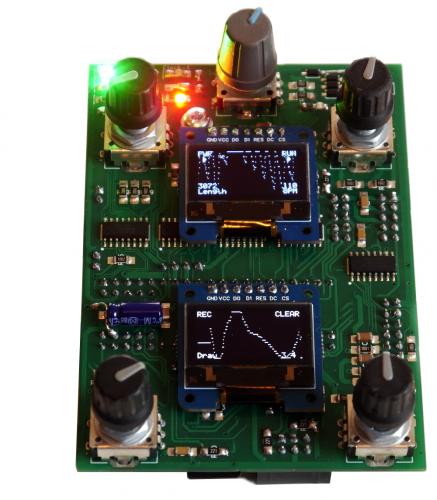
 Hello everybody, These are some design Questions! I was wondering about assembling some midibox modules to achieve a little graphical ocilloscope to watch my audio/CV like in this vid : https://www.youtube.com/watch?v=utr23hp2nRM (like on the 4 OLED screens) - I think a great part the work is already accomplished if TK already realized that. Am I Wrong? - What is the exact voltage range of the Core32 DACs ?. Edit : From The Ucapps Page STM32F4 Core module : 0-3.3V for native ADC From AINSER Module Page : 0-5V - Audio Inputs Should be ok for Core32 DACs/AINSER? What about bipolar voltage?And if i have "high" voltages like for example +15/-15v , is an OpAmp setup with dividing gain of 3 ok to reduce voltage range to -5v/+5V? - What is the biggest resolution and screen size that MIOS32 already supports? (i was expecting a 5cmx5cm wide 256px*256px monochrome display or something like that) - Is the combination of Core32+AINSER8 is modules enough to support 8 analog inputs (audio/CV)? I also thought Few DIN/DOUT Serial Registers may allow to have a little Control Surface to switch between inputs and make few changes about display calibration. Please correct me if i am going in a dead end way =) Thanks in advance for your advices! Greets, Jerome
 -

Noob wants to build a USB Traktor DJ-controller
Phatline replied to MissingNo's topic in MIDIbox User Projects
no sound card on midibox. but Midi via USB to Control Tractor. what you probally need for FADERS (if you need more then 8 Pots and Faders): http://www.ucapps.de/mbhp_ainser8.html or http://www.ucapps.de/mbhp_ainser64.html and as Brain and Midinterface to Traktor: http://www.ucapps.de/mbhp_core_stm32f4.html The Firmware you might use is: http://www.ucapps.de/midibox_ng.html it is not out of the box "Traktor" its out of the Box "Midicontroller" - so you have to configure it. and not necessery, but usefull a Dislplay: http://www.ucapps.de/mbhp_lcd.html you also will need Mios Studio to upload new Code or to Configure your Midicontroller (if you dont use LCD thats the way to configure): http://www.ucapps.de/mios_studio.html but first after you finished your CORE-STM32F4, you have to upload the bootloader: http://www.ucapps.de/mios_bootstrap.html- 1 reply
-
- 1
-

-
Does anyone have any info for the MB909 sequencer for the 9090 TR-909 clone. I need to know how it was connected to the STM32F4 core board as I only have a wiring diagram for the LPC17 core. Thanks
-
mb909hex.zip STM32F4 and LPC17 build.... i got some warnings when building LPC17 --- so try it out.
-
Ok, I know this project seems a little too much and it’s probably near impossible of not impossible to do, but I want to try it anyway… I want to build myself a DAW controller based on the design and layout of the SSL Origin console. I don’t need such a big controller and its in no way logical to build one and put this much time in this project, but I just love the idea of having a nearly two meters wide mixing console as the centerpiece of my studio. The plan I created in the last month: The controller should consist of 32 channels with one motorfader and 38 buttons/ potis each. On top of that is a mastering section with 8 additional Return/Send/Bus faders, wich will be normal 60mm faders and some basic daw control buttons like play/stop/record. The channel strip consists of the SSL E series eq and 8 additional potis controlling the different Bus channels. On the DAW side I want to build a template with all plutins loaded and with the right mapping, so that I can start working on the console immediately. Now to the hardware: Adding all channels and the mastering section there will be a total of 1246 buttons, faders, or potis and 32 motorized faders. I’m still quite new to this whole universe, so hopefully somebody could look over my thoughts and correct my if I’m (most likely) wrong. I need to read 1246 buttons/faders/potis. I chose the CORE_STM32F4 as my core and want to expand the inputs using the AINSER64 Module. I read there is a way to connect more than two AINSER 64 to a STM32F4, but I didn’t quite understand how this would work. I found a forum post writing about three AINSER 8 connected to a core. Is there the possibility to connect even more? If I think of two AINSER 64 per core, this would mean I can read 128 buttons, etc with one core. So I would need 10 cores for the not motorized knobs etc alone. Is this possible? Can I connect 10 cores all via usb to my pc and program them to one big controller? On top of that I would use the MF module for the motorfaders. Using 32 motorfaders I would need four Mf modules. Since I think there is the possibility to cascade multiple MF modules there would only be one USB running to the pc, right? I have many more things planned and a truckload more of questions, but I will just leave this here as it is and get to the other questions at a later time. I know this is a HUGE project - especially for a newbie and I don’t want to confront anyone, or come across as arrogant. I simply cannot get this out of my head and usually the best way to get it out is eventually just starting the project. This will surely take a long while to be build and programmed and I already have some friends and family helping me with designing, soldering and programming. I’m really looking forward to this project and cannot wait to show my process here. Sincerely Frederik
-
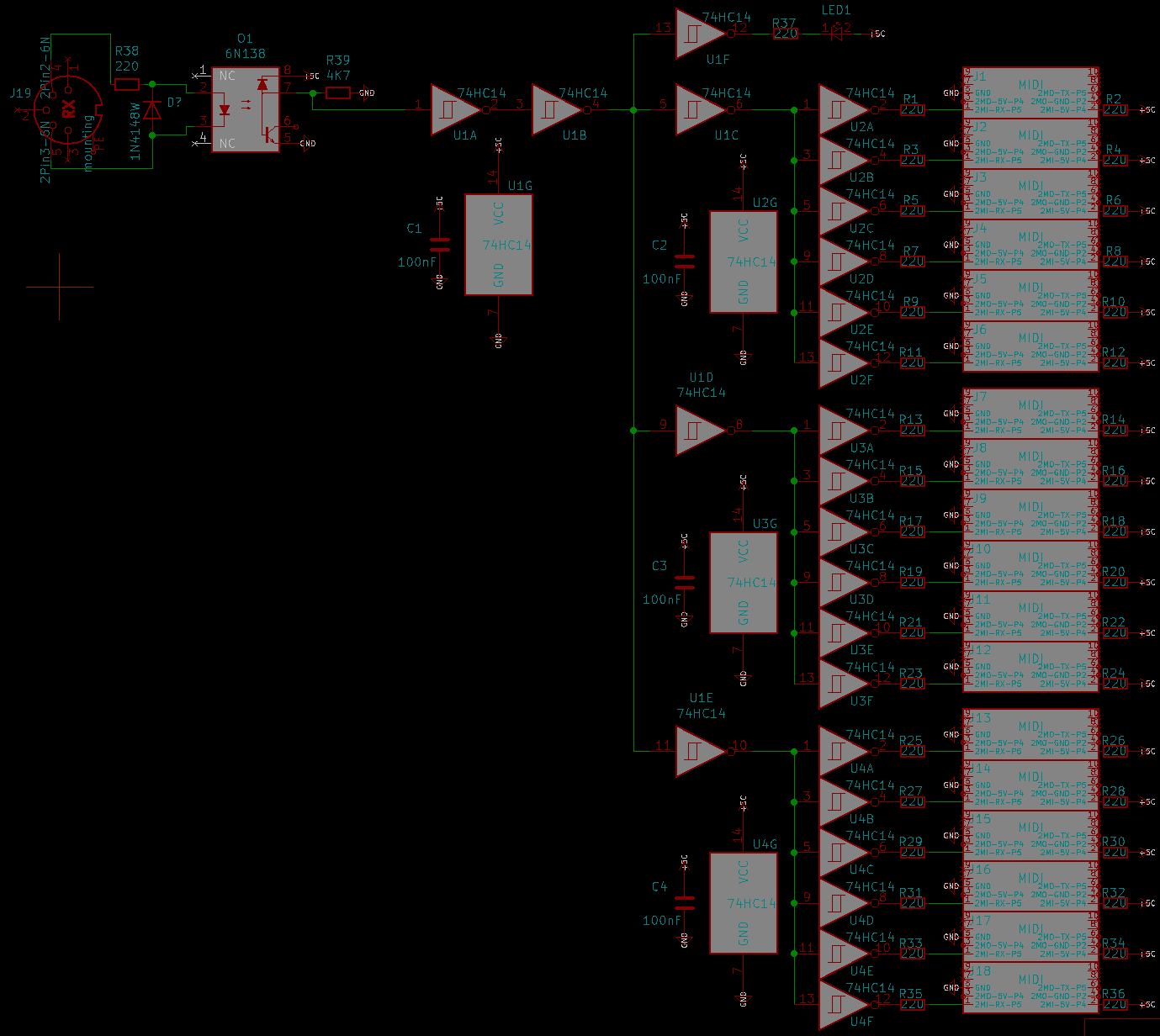
i need to handle up to 16 (MIOS32) Devices, The OUT >>> Thrubox is the simple thing (i think), is that Shematic correct? (ignore the boxes on the rightside, these are Shroudet Pinheaders to cable my devices with Ribboncables...since that is cheaper then the DIN-Thing) I know there will be a M16-Module, but i think for my task it is a bit overkill (maybe on price...) but what is when i have 16 MIDI-IN to handle, merge isnt possible or?, or is it possible to adress 16 MidiinPorts on a STM32F4? else it will be M16 in the end.... background: I need to copy/route Patches (arreys of Data) from one Device to the other. (a recordet Envelope, Size off [4][4096]), dont really know at the moment how to achive that (Sysex?) there is one Remote Device, and 16 Slaves.... - so the data should be sent from one Slave to the Remote Device, and from the Remote Device there it will be sent to one of the other Slaves.... (they share the same PSU) ...CV1...
-
Happy New Year to you all... I see you are now confirming build numbers to finishers - out of curiosity, do you know what mine was (completed beginning May 2019)? I was also just doing a new year firmware update on all my hardware - I'm running 097 on the V4+, but the download page stops at 096 (for STM32F4). Am I up-to-date? Cheers, Simon
-
The LPC17 is not bad and should work for the purpose, but it's outdated and the direct successor is the STM32F4. If you haven't bought anything, then go for the 'newer' board. But I don't have an AINSER 64 and can only say what is generally known about the cores. (PCBs can be purchased from 'modular addict').
-
That's all right - for the software it is a SEQ v4+, if it has a STM32F4 with 1MB of flash memory - it just can't use the extended UI features of the midiphy SEQ v4+, primarily the secondary selection row and the TPD/Activity Matrix - using the Wilba hardware config file should work fine.
-
This was a nice challenge for the weekend: I implemented a driver for USB MIDI Host mode into MIOS32 for STM32F4 :smile: (LPC17 and STM32F103 don't support USB Host mode...) Tested with following devices: CME X-Key: Waldorf Blofeld: MIDIbox (here MIDIbox SEQ V4L): Ploytec GM5x5x5 USB MIDI Host mode just replaces USB MIDI Device mode via the USB OTG socket. The update will be available with all future MIOS32 applications, it's always available without special configuration. A special USB Micro-B -> USB 2.0-A adapter is required to connect the MIDI device. Such an adapter is for example available at Reichelt (DELOCK 83183) for 5 EUR: http://www.reichelt.de/DELOCK-83183/3/index.html?&ACTION=3&LA=446&ARTICLE=126860&artnr=DELOCK+83183&SEARCH=DELOCK+83183 Pluck this adapter into the Micro-USB socket of the STM32F4-Discovery board, reset (or power-cycle) the core, and MIOS32 will automatically switch to USB Host mode. Limitations: - USB hubs are not supported, the MIDI device has to be connected directly. - USB based Power-Supply is weak (limited to ca. 200..300 mA), which means that it might be required to power the MIDI Device with an external PSU - the MBHP_CORE_STM32F4 module has to be powered from the USB debug socket Please let me know if you are interested to beta-test this enhancement, I could provide a preliminary version of a MIOS32 application. Best Regards, Thorsten