CJ55
-
Posts
64 -
Joined
-
Last visited
-
Days Won
4
Content Type
Profiles
Forums
Blogs
Gallery
Everything posted by CJ55
-
Good work!
-
The value of the caps depends also on the crystal/quartz. Some need 18pF, other 32pF for example. Check the data sheet of the crystal/quartz you are using.
-
You can add a DOUT to Wilba's frontpanel without problem.
-
With a pair of MIDI_IO PCBs you get 4x MIDI In and 4x MIDI Out. For more MIDI Outs you need the Quad IIC MIDI Module (for four additional MIDI Outs). The AOUT_NG is only for the 8 CV-Outs. For the Gate-Outs you need a DOUT(X4) module (for up to 32 Gate-outs).
-
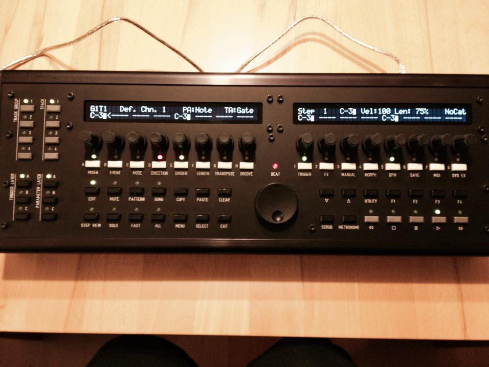
Features of the Midibox SEQ V4: optimized for live playing and editing intuitive user interface with flat menu hierarchy, wide screen display (2 * 2x40 = 160 characters) and 16+1 rotary encoders with menu page dependent "soft function". multiple MIDI Out ports (up to 12) for reduced MIDI latency up to 4 MIDI In ports (e.g. for separated MIDI clock and MIDI keyboard inputs) USB interface which supports USB MIDI protocol to send events more than 100 times faster optional Ethernet interface for sending/receiving OSC packets (or MIDI events embedded into OSC packets) every parameter can be modified in realtime w/o affecting the sequencer timings one sequencer pattern consists of 4 independent tracks four patterns can be played at the same time -> makes 16 tracks each track consists of up to 16 layers which can be assigned to various parameters (e.g. Note/Velcity/Gatelength/Chords/CC/PitchBender/Delay/Probability/Roll) Transpose and Arpeggiator function Force-to-Scale function with 166 predefined scales Track directions: Forward/Backward/PingPong/Pendulum/Random Dir/Random Step Track direction progressive parameters (Step Forward, Jump Back, Repeat, Interval, Skip, Repeat) free adjustable clock divider for each track. Supported timebases 1..256, normal and tripled available length for every track: 1-256 steps with 384ppqn resolution, 256th notes can be played loop point within track step events can be triggered multiple times (up to 4 times per step) with a delay value of 1-31 to realize drumrolls, ratterbeats, flams... 8 trigger layers for Gate/Skip/Accent/Glide/Roll/Random Gate/Random Value/No Fx various Groove styles (shuffle/inverted shuffle/...) + customizable Groove Templates (Delay/Length/Velocity) Humanizer function (random modification of note/velocity/gatelength) Pattern Morphing, controllable in 128 steps with a Modulation Wheel Echo Fx with Repeat/Delay/Feedback/Note increment/Gatelength/Delay parameters LFO Fx with different waveforms, synchronized period length, adjustable reset point, phase, OneShot mode. Assignable to Note/Velocity/Length/CC Note Limiter Fx Manual step triggering Step and Realtime Record function Copy/Paste/Clear function Scroll and Step Move function Random and Euclidean pattern generator Undo function parameters of multiple steps can be changed relatively and absolutely with a single rotary encoder parameters of multiple tracks can be changed the same time with a single rotary encoder Tracks and parameter layers can be muted Accent/Slide/CC sequences inbuilt MIDI mixer/controller with 128 free definable mixer maps inbuilt MIDI router virtual "Loopback port" for Master/Slave tracks split function for Transposer/Arpeggiator 8 optional CV outputs and gates for analog gear CV outputs can also be accessed from MIDI In (-> replaces a CV interface) 64 optional 1 mS drum trigger outputs 8*128 patterns are stored on SD Card 128 mixer maps are stored on SD Card pattern sets can be looped and chained in song mode phrase mode which allows to switch between the 16 predefined pattern sets (for fills/breaks/chorus, etc...) pattern switching can be synchronized to the measure MIDI Remote functions 2.5-300 BPM (MIDI clock master) external sync (MIDI clock slave) DIN sync output for controlling vintage sequencers works with 16x MIDI clock resolution (384 ppqn) several hardware options (e.g. a 64 Button/Duo-LED matrix) details and demo samples in the User Manual DIY ONLY!!! (commercial release neither planned, nor allowed!)
-
Die Strom- (A) und Spannungs- (V) Angaben bei den Tastern sind Maximalwerte. Die MIDIbox Elektronik arbeitet mit nur 5V.
-
Der größte Unterschied ist das Maß der Aufnahme: 3,3mm (Digikey/Mouser) gegenüber 3,8mm (Conrad). Die Frage ist also, ob du passende Kappen hierfür findest.
-
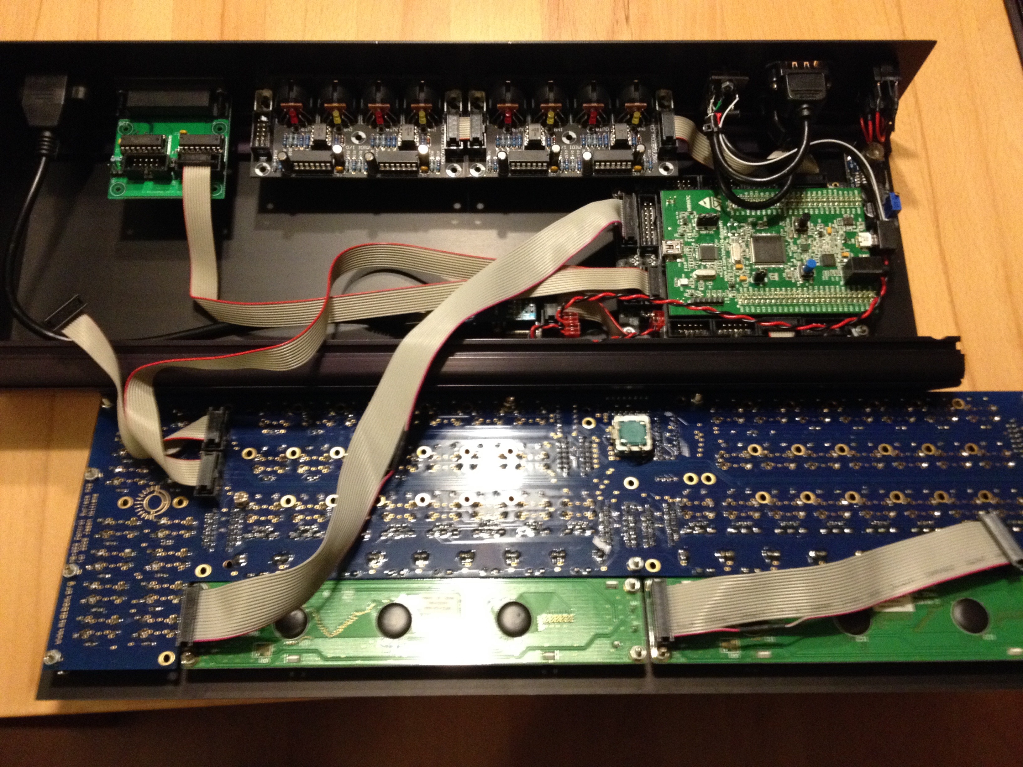
@FantomXR: you have to connect the USB-device to the micro-USB port, not the mini-USB port! And you need a USB OTG adapter cable. Booting the STM32F4 with this adapter cable activates the USB host mode. You can use the mini-USB port to power the board, though. Or use an external power supply.
-
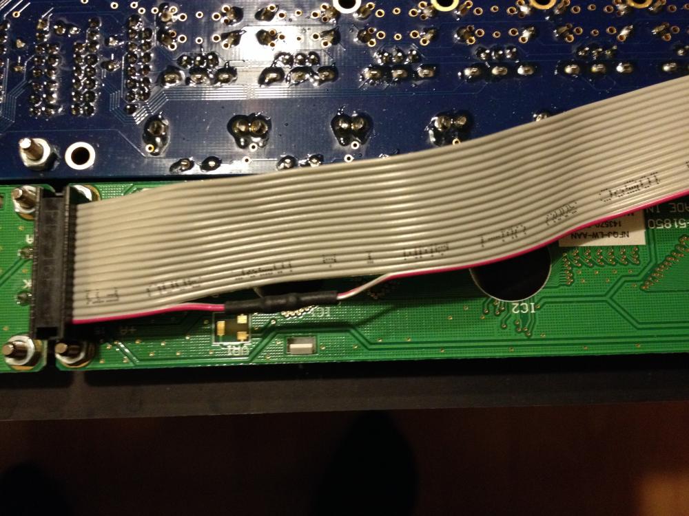
No, the resistor is only there to protect the backlight LEDs of the display for to much voltage. The max. voltage for the backlight LEDs is 4V (or typ. 3.5V). The advantage of this resistor is, you don't need to change anything on the MB_CORE_STM32F4. But you can still use both trimmers on it without the danger of giving the display to much voltage. One trimmer is for contrast, the other for backlight brightness. How to calculate the resistor: you have the current of the backlight LEDs: 60mA (datasheet). The same current flows through the resistor (series circuit). The voltage at the resistor is 5V - 3.5V (datasheet) = 1.5V. Then Ohm's Law: R = U/I = 1.5V / 0.060A = 25 Ohm If you can not get a good contrast/brightness ratio with both trimmers, then you can try Altitudes way and remove transistor T1, resistors R12, R13 and trimmer P. And connect an other (better) trimmer directly between pin B- of J15 and ground. But you have always to make shure, you have the 25 Ohm resistor in there. Either here in series with the trimmer or in the cable. Most displays have this resistor built in, so you can connect the backlight directly to 5V, but unfortunatly not all.
-
I think, that's an error in the description of the MB CORE_STM32F4. You have to use one of the four MIDI I/Os at J11E. MIDI at J5B is only provided on older COREs.
-

-
I use this display on my MB SEQ V4 with the STM32F4 Core and on other stuff. You have to consider that the backlight must not connected to 5V directly. It needs an additional resistor (25 Ohm) between pin 15 of the display and the Core. Otherwise it get destroyed (own experience)! See point 2.4.2 of the datasheet.
-
Do you have a SD card connected with the right configuration of the MBSEQ_HW.V4 file for the CS? You can find it here: http://svnmios.midibox.org/filedetails.php?repname=svn.mios32&path=%2Ftrunk%2Fapps%2Fsequencers%2Fmidibox_seq_v4%2Fhwcfg%2Fwilba%2FMBSEQ_HW.V4
-
Actually the DOUTx4 has only 4 ICs (74HC595). The other 4 which look like ICs are actually resistor arrays (8x 220Ohm) in DIP housings. You can also use 32 discrete normal resistors.
-
Yes, that should work, but two notices: 1: the MBHP_CORE_STM32F4 do not deliver enough current (mA) and only 3.0 V at J16 instead of 3.3 V. So you need an additional voltage regulator (5V ->3.3V). 2. the connector pin layout is obviously not the same as J16
-
Which encoders should I buy for SEQ V4 build?
CJ55 replied to fundamental's topic in Parts Questions
I use the Bourns PEC16-4220F-S0024 with push button. After I ordered them from Mouser I read here in some older threads, that some people had problems with them. But they are working great with my MB SEQ V4 with CS PCB. No problems at all. http://www.mouser.de/Search/ProductDetail.aspx?R=PEC16-4220F-S0024virtualkey65210000virtualkey652-PEC16-4220FS0024 -
Do you plan to sell these boxes? There is already the mighty Eventide H9, which you can also control by mobile app. Or will it be a DIY project? Or is it just for learning perposes?
-
This will not work! Why don't you just use the recommended STM32F4DISCOVERY board. Its available for only €15,00. Have you read this: http://www.ucapps.de/index.html?page=mbhp_core_stm32f4.html ?
-
Hi, sieht so aus, als wenn Du die Pins falsch zählst. Wenn beim IC die Kerbe (oder Punkt) links ist, dann ist Pin 1 unten links. Dann wird gegen den Uhrzeigesinn weitergezählt. Wenn die Kerbe rechts ist, dann ist natürlich das ganze um 180 Grad gedreht. Und wenn Du von der Unterseite (Lötseite) zählst, dann ist das ganze spiegelverkehrt ;-) Am besten googlest Du mal nach den entsprechenden ICs und guckst dir die Datenblätter an.
-
Connection looks good, except that pin 9 has also to be connected to GND. No jumpers need to be removed.
-
Some posts ago you wrote you have pin 2 connected to PC5, but it has to be PA7. And do not connect pin 3 (GND) with pin 4 (+3.3V)!
-
Maybe this is helpful: This is the SD card holder I use: http://www.mouser.com/ds/2/1/ts2198-49568.pdf The main difference is that your card holder has an additional unnamed pin between pin 2 and 3. This is how my card holder is connected: 9 GND 1 PB2 2 PA7 3 GND 4 +3.3V 5 PA5 6 GND 7 PA6 8 not connected
-
Yes, that is a bit confusing. According to the data sheet Pin 3 is GND and Pin 4 Power Supply.
-
Why did you solder pin 3 and pin 4 together???
-
Ja , Tim aka Smash hat sich gestern gemeldet :-)