Phatline
-
Posts
1,285 -
Joined
-
Last visited
-
Days Won
72
Content Type
Profiles
Forums
Blogs
Gallery
Everything posted by Phatline
-

dipCoreF4 and dipBoardF4, a compact Core.
Phatline replied to Antichambre's topic in Design Concepts
and i didnt change anything except deleting the Midi-lines in MIOS-Config, and updateting the Repo. i uploadet the Bootloader app again, to change the Display settings manually, but they are already set, like it was bevore (where it was running), buy changing the type from rotating (which i need) to not rotated for example did not change the problem, or by changing the lcd_num x to 1 (two i had)... . no Picture on Booth SSD1306 when using the bootloader app, one display when use-ing my app. i also restored my mios-config settings as they where before... but still one display! I swapped (mios config side) Y to2, and X to 1 - and now it works.... I dont understand this, it was a X2 Y1 bevore. (crazy) ok later the day one display fault again.... (same code) i measured the "Reset" Resistor (1K) and i had 760OHM... the Reset Voltage was about 2.5V.... on the working Display i had 3.3 Volt - and a Resistance from 980 Ohm.... (1Ks are installed)... so i cleaned the soldering Points of the display, after removing the FLUX i got a Working LCD and a Voltage from 3.3V .... low impadance Flux - GOOD NIGHT!
-
dipCoreF4 and dipBoardF4, a compact Core.
Phatline replied to Antichambre's topic in Design Concepts
I updatete the repo, and deletedet the uneccersery lines in mios-config. its no long test, but on the moment its running without HARD-FAULT, and it is recognized in Mios-studio without Bootload-Mode! thx! BUT now Display1 stays dark, it is connected to Pin 33, PB12-J15.CS1 (it was working bevore) Display 2 is working, it is connected to PIN 27, PC0-J15.CS2 -
dipCoreF4 and dipBoardF4, a compact Core.
Phatline replied to Antichambre's topic in Design Concepts
hmmm... serios problems here when i connecting the dipcore via Dipcores-onboards USB-Socket to my Laptop (lenovo thinkpad t440p, linux mint): i get after a few seconds after booting up a: !! HARD FAULT !! at PC=0x0801afd4 or it doesnt boot at all it doesnt matter if the Laptop is on battery only, or with PSU-connected (so it isnt a noisy psu) I doesnt measured a Voltage Dropdown on the USB-RAIL (measered on the PTC) while Hardfaul accours... i doesnt Activated "Midi via USB" since config is: #define MIOS32_USE_MIDI #define MIOS32_USE_UART #define MIOS32_USE_UART_MIDI #define MIOS32_UART_NUM 1 #define MIOS32_UART0_ASSIGNMENT 1 //1=Midi, 0= Disabled, 2= COM #define MIOS32_UART1_ASSIGNMENT 0 #define MIOS32_UART2_ASSIGNMENT 0 #define MIOS32_UART3_ASSIGNMENT 0 (right?) it doesnt fault (no time) when i connect the same USB to a Mobilphonecharger (2A) and it doesnt fault ... when running (almost) the same app on LPC17 > CV1 ok that tell us NOT much, because the LPC17 is no STM32 chipset... ... also most of the time the Dipcore isnt regognized via MIOS-Studio - i have to go into Bootload Mode(via Switch) to upload new code.... (i dont scan any J5 or other GPIOs which could force floating data mess) --- i updatet today the repo from your github... so its actual ( i cant say if it worked before... its long ago since i codet on a dipcore) i tried different USB ports from my laptop, also the one Port which is a "always on to charge whatever usb) make the same hard fault The app doenst boot up on a windows 10 Desktop PC at all (no time!) (no screen content on the SSD1306) on a other windows 10 Desktop it boots, but it Hardfaults the same way like on my Linux laptop. i bridget the VBAT! (use SD-Card and SSD1306!!!), because i have to supplay a "motherboard" > CV-1-Shematic.pdf i already had deactivated all SD-Card Routines, and Scan Routines, but the machine hangs on almost "background" tasks... so i turned it on again. here is the APP i programm... CV-ONE-V0.zip ==============================================================0 i use the bootloader from here: http://wiki.midibox.org/doku.php?id=dipcoref4 > (i dont change anything in bootloader via Terminal --- i changed the display settings within the app --- so its almost stock) http://wiki.midibox.org/lib/exe/fetch.php?media=antichambre:dipcoref4_bootlader.zip i updatedt today the mios repo from: https://github.com/antichambre/MIOS32 gcc-arm-none-eabi is still from 2013 ( i dont updatet anything there) and of course the environment variables are set correct: MIOS32_PATH=~/midibox/mios32 MIOS32_BIN_PATH=$MIOS32_PATH/bin MIOS32_BOARD=MBHP_DIPCOREF4 MIOS32_FAMILY=STM32F4xx MIOS32_GCC_PREFIX=arm-none-eabi MIOS32_PROCESSOR=STM32F405RG MIOS32_LCD=universal the app is functional as i said but not on computers... on smartphone chargers i dont get a Error! -
Audio/CV Signal Display : Graphical Oscilloscope with Midibox
Phatline replied to Psykhaze's topic in Design Concepts
any progress on something like this? -
Noob wants to build a USB Traktor DJ-controller
Phatline replied to MissingNo's topic in MIDIbox User Projects
no sound card on midibox. but Midi via USB to Control Tractor. what you probally need for FADERS (if you need more then 8 Pots and Faders): http://www.ucapps.de/mbhp_ainser8.html or http://www.ucapps.de/mbhp_ainser64.html and as Brain and Midinterface to Traktor: http://www.ucapps.de/mbhp_core_stm32f4.html The Firmware you might use is: http://www.ucapps.de/midibox_ng.html it is not out of the box "Traktor" its out of the Box "Midicontroller" - so you have to configure it. and not necessery, but usefull a Dislplay: http://www.ucapps.de/mbhp_lcd.html you also will need Mios Studio to upload new Code or to Configure your Midicontroller (if you dont use LCD thats the way to configure): http://www.ucapps.de/mios_studio.html but first after you finished your CORE-STM32F4, you have to upload the bootloader: http://www.ucapps.de/mios_bootstrap.html- 1 reply
-
- 1
-

-
http://wiki.midibox.org/doku.php?id=lre5-lcd2 well currently waiting for the boards to come.

-
Various C64 and MIDIbox parts - should I sell or trash?
Phatline replied to pingosimon's topic in MIDIbox SID
your in US... so nothting for me.... I would keep the C64s Keycaps, there are people who wants them - not specially here... DIN DOUT always good for a quick prototyp, the PSUs also usefull. -
Test-App: tpd-test.zip And how you doing....
-
yes, i tried several times to understand the seqv4_ in the end i did not understand, and endet by diy from ground. my c- vocabular is based on "need to know" to get it fixed, and while duing stuff it grows.
-
thx!
-
ok solved it with: // BPM u16 value= BPM*10; buf[7] = value % 10; value = value / 10; buf[0] = value % 10; value = value / 10; buf[1] = value % 10; value = value / 10; buf[2] = value % 10;
-
Hi, i am currently finishing the TPD-Displays PCBs, and i write a Test App/or my first skeleton-UI to use it. Its all clear so far, i can print single digits, i know the pattern, the pinout..... i want to print for example: float BPM = 128.5; // for Example for Digit 1 2 8 5 --- As BPM Display but i stuck by Divididing the BPM Value into single Integers, by searching in internet i found: int i = BPM*10; // Elemenate FLOAT Digit! static char buf[4]; sprintf(buf, "%05.2f", i); // split it into CHARs but that dont work at all... (print "0" on the first digits, the others are OFF) i later print the "buf[x]" value to my Digit --- that works fine, when initalize "TPD_SEG" by hand with iniatl values, but not when filled with above code! // Transcode To Shiftregister-Friendly Array static u8 x=0; for (x=0; x<4; x++) { // 7 Segment PINOUT // [6] // [1] [5] // [0] // [2] [4] // [3] [7] // switch (buf[x]) { case 0: TPD_SEG[x][0] = 0; TPD_SEG[x][1] = 1; TPD_SEG[x][2] = 1; TPD_SEG[x][3] = 1; TPD_SEG[x][4] = 1; TPD_SEG[x][5] = 1; TPD_SEG[x][6] = 1; TPD_SEG[x][7] = 0; break; case 1: TPD_SEG[x][0] = 0; TPD_SEG[x][1] = 0; TPD_SEG[x][2] = 0; TPD_SEG[x][3] = 0; TPD_SEG[x][4] = 1; TPD_SEG[x][5] = 1; TPD_SEG[x][6] = 0; TPD_SEG[x][7] = 0; break; case 2: TPD_SEG[x][0] = 1; TPD_SEG[x][1] = 0; TPD_SEG[x][2] = 1; TPD_SEG[x][3] = 1; TPD_SEG[x][4] = 0; TPD_SEG[x][5] = 1; TPD_SEG[x][6] = 1; TPD_SEG[x][7] = 0; break; case 3: TPD_SEG[x][0] = 1; TPD_SEG[x][1] = 0; TPD_SEG[x][2] = 0; TPD_SEG[x][3] = 1; TPD_SEG[x][4] = 1; TPD_SEG[x][5] = 1; TPD_SEG[x][6] = 1; TPD_SEG[x][7] = 0; break; case 4: TPD_SEG[x][0] = 0; TPD_SEG[x][1] = 1; TPD_SEG[x][2] = 0; TPD_SEG[x][3] = 0; TPD_SEG[x][4] = 1; TPD_SEG[x][5] = 1; TPD_SEG[x][6] = 0; TPD_SEG[x][7] = 0; break; case 5: TPD_SEG[x][0] = 1; TPD_SEG[x][1] = 1; TPD_SEG[x][2] = 0; TPD_SEG[x][3] = 1; TPD_SEG[x][4] = 1; TPD_SEG[x][5] = 0; TPD_SEG[x][6] = 1; TPD_SEG[x][7] = 0; break; case 6: TPD_SEG[x][0] = 1; TPD_SEG[x][1] = 1; TPD_SEG[x][2] = 1; TPD_SEG[x][3] = 1; TPD_SEG[x][4] = 1; TPD_SEG[x][5] = 0; TPD_SEG[x][6] = 1; TPD_SEG[x][7] = 0; break; case 7: TPD_SEG[x][0] = 0; TPD_SEG[x][1] = 0; TPD_SEG[x][2] = 0; TPD_SEG[x][3] = 0; TPD_SEG[x][4] = 1; TPD_SEG[x][5] = 1; TPD_SEG[x][6] = 1; TPD_SEG[x][7] = 0; break; case 8: TPD_SEG[x][0] = 1; TPD_SEG[x][1] = 1; TPD_SEG[x][2] = 1; TPD_SEG[x][3] = 1; TPD_SEG[x][4] = 1; TPD_SEG[x][5] = 1; TPD_SEG[x][6] = 1; TPD_SEG[x][7] = 0; break; case 9: TPD_SEG[x][0] = 1; TPD_SEG[x][1] = 1; TPD_SEG[x][2] = 0; TPD_SEG[x][3] = 1; TPD_SEG[x][4] = 1; TPD_SEG[x][5] = 1; TPD_SEG[x][6] = 1; TPD_SEG[x][7] = 0; break; } }
-
2 left...
-
I have 3 TIA Cartridge PCBs, pay me the postage (AUSTRIA) - and i give it away for free: for info see here: http://wiki.midibox.org/doku.php?id=midibox_tia#the_midibox_tia_cartridge_version What not includet is: the 24LC512 aka "Bankstick", the 7805 aka "Voltage Regulator", the TIA aka "Soundchip", the 6N138 aka "Optocoppler". the 24LC512 to solder is not for Beginners! the Microcontroller is Preprogrammed with MIOS.


-
mb909hex.zip STM32F4 and LPC17 build.... i got some warnings when building LPC17 --- so try it out.
-
do you need it for lpc17 or STM32F4 board? (ask because the tread was started for the other way round...)
i cant download the Gitubfiles (dont see a download button, and i am a offline coder...)... so i can take the one i have on harddisc - it is from 23.OCT 2018 (dont know if they are the same)--- or you show me how to download it...
-so lpc or stm32F4?
-
send me the source-files (or give me a link), and i compile it... (but dont ask me about the firmware, didnot used it, nor i was involved in it...)
-
LRE 4x1 breakable RGB LED-Ring/Rotary-Encoder PCB bulk order
Phatline replied to weasel's topic in Bulk Orders
Question: at the end, what is the performance of this RGB-Ledrings - in sence of RAM, CPU, and so on... I imagine a simple midi-controller app, will do fine, BUT: i am asking, since most my applications are on the limits on the Microcontroller (mostly ram, sometimes CPU, > sequencers, synths), is this done by CCRAM now, is it the same perfomance like using H595 Registers and some single Color LEDs, some kind of background task? or is this heavy load, and i should forget the last 3 Pages i read...? If i have already a APP that uses 90% or more RAM (for example) will force that to NOT boot anymore? (i have read the last 3 pages) thx for sharing your experiance -
handle multiple Mididevices (up to 16) Thrubox? Merge? M16?...
Phatline replied to Phatline's topic in Design Concepts
Ah... i thought they have to be inverted back, thinking of the signal is 180° "inverted" and has to be "inverted again"... (yes Midibox cores...) Good to know that the ID will manage the Sysex "Channel"! -
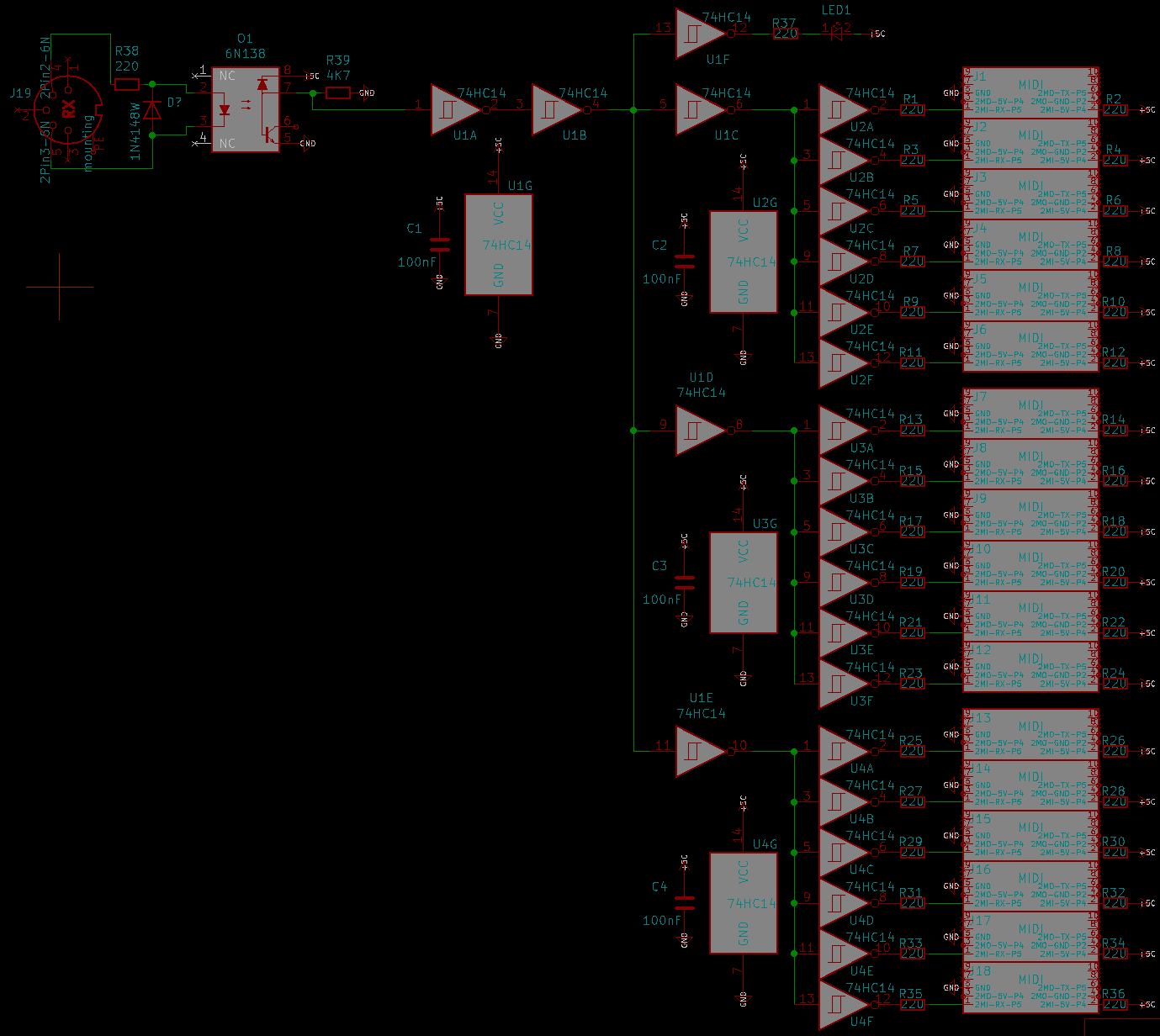
i need to handle up to 16 (MIOS32) Devices, The OUT >>> Thrubox is the simple thing (i think), is that Shematic correct? (ignore the boxes on the rightside, these are Shroudet Pinheaders to cable my devices with Ribboncables...since that is cheaper then the DIN-Thing) I know there will be a M16-Module, but i think for my task it is a bit overkill (maybe on price...) but what is when i have 16 MIDI-IN to handle, merge isnt possible or?, or is it possible to adress 16 MidiinPorts on a STM32F4? else it will be M16 in the end.... background: I need to copy/route Patches (arreys of Data) from one Device to the other. (a recordet Envelope, Size off [4][4096]), dont really know at the moment how to achive that (Sysex?) there is one Remote Device, and 16 Slaves.... - so the data should be sent from one Slave to the Remote Device, and from the Remote Device there it will be sent to one of the other Slaves.... (they share the same PSU) ...CV1...
-
i renamed the title...treat thread thanks! English: mounting-block/cube , cube standoff German: Gewindeblock or Montageblock or better Leiterplatten-Montageblock (because Montageblock is used for Water-Installation-"Montageblocks" too) buerklin (29,75 € incl VAT, excl Shipping) ettinger (52,44 € incl VAT, excl Shipping) a bit strange that Reichelt/Mouser doesnt have it, they all have such Nylon Variants: https://www.reichelt.com/de/en/mounting-block-m3-16-mm-natural-rnd-610-00209-p254065.html?r=1
-
Does someone know what name this M3 standoff has? It is used for example to mount PCBs to a Frontpanel! Name in German/English, and maybe where to get them. thx!

-
dipCoreF4 and dipBoardF4, a compact Core.
Phatline replied to Antichambre's topic in Design Concepts
Yes need it for a MCP6002 Rail.... is the jumper on the BOTTOM of the Dipcore? -
i made PCB for Pick and Place Service... and updatet the Wiki: (now waiting for the boards to come) clock2audio2clock


-
dipCoreF4 and dipBoardF4, a compact Core.
Phatline replied to Antichambre's topic in Design Concepts
ok then i take J16 RC2 (PA4) and J16 RC1 (PC4) which are used for SD-Card - which i dont need here. so i gues MIOS32_DONT_USE_SDCARD ? @ Type DEF - is this done like on J10 for example: MIOS32_BOARD_J10_PinInit(0, MIOS32_BOARD_PIN_MODE_OUTPUT_PP); MIOS32_BOARD_J10_PinSet (0, 1); for me Clear how to make it with J5 and J10 >>> MIOS32_BOARD_J16_PinInit(0, MIOS32_BOARD_PIN_MODE_OUTPUT_PP); ??? thx