ilmenator
-
Posts
2,305 -
Joined
-
Last visited
-
Days Won
37
Content Type
Profiles
Forums
Blogs
Gallery
Everything posted by ilmenator
-
Hallo und sei willkommen hier! Die Liste sieht soweit gut aus, das PDF-Anhængen scheint nicht geklappt zu haben, zumindest gibt es keinen Link in deinem Beitrag. Evtl. macht es Sinn, nicht mehr auf den LPC Core zu setzen, sondern stattdessen auf den STM32F4 Core. Eine entsprechende Core- und (hier "ausgelagerte" MIDI Port-)Platine gibt es in Tim's MIDIbox Shop. Beim LPC17 gab es eine nicht dokumentierte Verschiebung der Pins des Moduls, so dass Rev. C nicht mehr mit "unseren" Core-Platinen kompatibel ist. STM32F4 ist leistungsfæhiger bei gleichem bis geringerem Preis. Gruesse, ilmenator Edit: jetzt gibt's auch einen Link - ja, sieht gut aus!
-
Hallo und willkommen hier! Die Platinen sind im MIDIbox shop von Tim aka SmashTV erhaeltlich - zweiter Eintrag von oben. Eigentlich sollte die ganze Doku inkl. Board und Layout auch auf ucapps.de zu finden sein, aber vermutlich ist Thorsten gerade zu beschaeftigt um da mal ein Update zu machen.
-
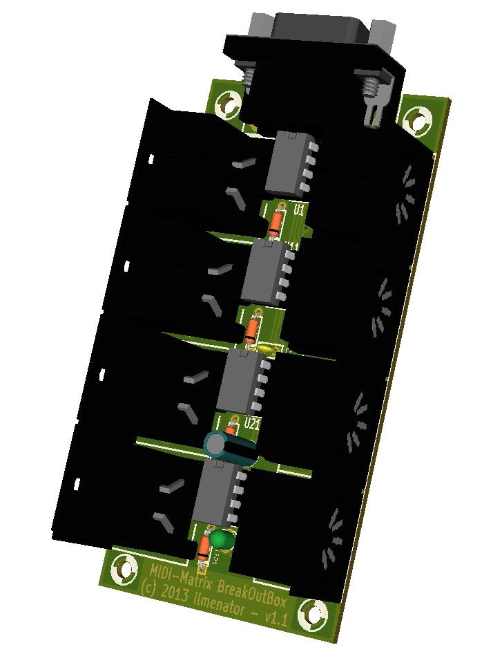
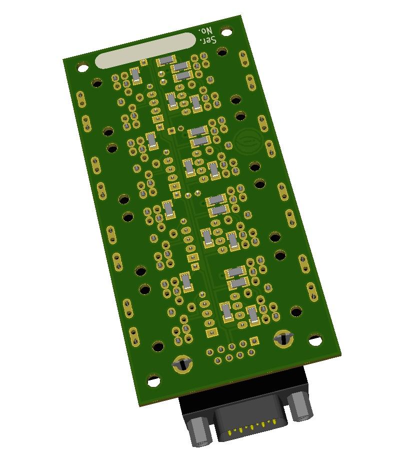
Yes, this should be possible - I have not tried this, though. I was mainly interested in generating a nice model, but maybe if one exported this and subsequently imported into a more complete renderer, it would be possible to create a nicer lighting?
-
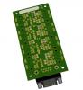
Here is a screenshot of KiCAD using the 3D extension by easyw. The only thing required to get this is to replace an .exe file in KiCAD's bin folder with another one, and add two DLLs. Now, if we could only set the light properly :-).
-
Then go for my second suggestion, connecting the rotary switch to a Digital In (DIN) board. I think this is much more straight forward than using the rotary switch to implement some voltage divider, which is then sampled by the analog input of the Core. Especially software-wise, using the DIN modules to send fixed CC values is dead easy. There is a code tutorial you might want to take a look at: you want to look at tutorial #010 "Scanning up to 128 buttons connected to DINX4 Modules"!
-
Why don't you use endless rotary encoders and instead of having them cover the full parameter range from 0-127, just "connect" them to a table of values, so turning them to the right one tick would change the CC 23 value from 14 to 45? Your solution seems to be very complicated to me! Or, use the rotary switch you link to above, and connect the pins to a DIN module that triggers the MIDI messages you want to send?
-
Not exactly, but then Mackie themselves claim that Mackie HUI is alive and well inside the Mackie Control Universal.
-
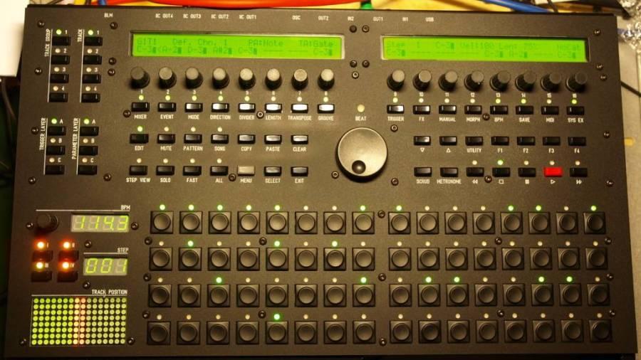
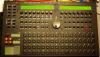
The lower part with the drum pads is not shown in this image, and the side panels are not mounted yet. I'll publish another picture when it's finally ready :smile:
-
Roland MV-8000 case here with a Ponoko front panel.
-
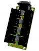
[S] TPD (Track Position Display) 5 semi kits for sale
ilmenator replied to ilmenator's topic in Fleamarket
Sure, PM sent! -
Eagle has some 3D rendering capabilities, maybe that could be a starting point - although I am not sure if this data can be exported. I am a KICAD user, and KICAD is using Wings3D to render PCBs and components. It is possible to convert the manufacturer's models (usually provided in STEP format) to be used in KICAD.
-
As SmashTV is selling this, your best bet is to ask him. However, I am pretty sure the documentation will be on ucapps.de sooner or later.
-
Yes, this has been very annoying - thanks for fixing this!
-
I guess Microchip have implemented this hurdle for a reason. It would be unwise to communicate "valid" email providers here, as Microchip would potentially be flooded with sample requests from people associated with these email providers, which eventually backfires to the original address holders by blacklisting their email providers...
-
I did not check Tim's shop, just the ucapps.de website - usually, the board layout is published there, and for the STM32F4 core board this is not the case, so I assumed it was still in the making.
-
STM32F4 is the way to go, but the core board is not available yet. Depending on your level of DIY skills this might be a reason for waiting some more until all parts necessary can be purchased from Tim's shop.
-
No, because the usual way to program the PIC is via the bootloader. You burn the bootloader on the PIC one time, and thereafter you transfer the OS (MIOS) and the program (MB-SID) via MIDI, using a tool called MIOS Studio.
-
Could someone explain to me what this is good for? Isn't it way cheaper and more practical to connect the faders via a 2-pin cable??
-
[S] TPD (Track Position Display) 5 semi kits for sale
ilmenator replied to ilmenator's topic in Fleamarket
Still available - you can also have just the printed circuit board, without the other parts, if you prefer. -
Two semi kits left.
-
Hallo Lutz, willkommen hier! Welches MIDI-Interface benutzt du für die Übertragung der Daten zum Core-Modul? Im Wiki gibt es eine Blacklist mit Interfaces die nicht geeignet sind - vielleicht schaust du da mal, ob deines dabei ist. Und: welche Bootloader-Version hast du auf deinem Core? Grüße, ilmenator
-
Maximum flexibility sounds good, but can easily turn into maximum confusion. A pin 1 marker is a must, I think - good that you have added this!
-
Maybe you could add some silkscreen hints on which side to solder the SIL header, and how it is oriented / connects to the display?
-
Yes, that is the recommended method anyways, even for the older rev B. Nothing to disagree here!
-
Well that's strange because from the picture that jab uploaded in the first post of this thread, it looks like we have an offset of exactly 1,27mm for pins 1-19: Looking at this, I think you are not actually talking about these pins, but that you soldered the two rows of headers onto LPC and core board separately and tried to stack them afterwards. That is not recommended practice anyways. So it seems like you are referring to something different than what this thread was originally about?