ilmenator
-
Posts
2,305 -
Joined
-
Last visited
-
Days Won
37
Content Type
Profiles
Forums
Blogs
Gallery
Everything posted by ilmenator
-
That's a design decision based on my specific "studio" setup and the costs involved in fabricating small boards in larger quantities (as opposed to large boards in smaller quantities). Also, with this specific implementation it is possible to use cheap serial cables that are available everywhere. Serial cable plugs can easily be secured against falling off their sockets, which is nice when some of your gear is mounted in racks with wheels. Absolutely yes. A BOB (Break-Out Box) can be connected to the new STM32F4 core board via J11E. It is a nice alternative to the I/O board that you can order together with the core board from SmashTV (and you only need one for all four I/O ports). I hope to find some time this weekend to design a little adapter board (from 10pin IDC connector to 9pin DSUB) with level shifting for the MIDI out signals. I am not sure it is a good idea to keep the MIDI signals at the 3.3V level if distances are getting larger. At a 5V signal level I have tested 25m by chaining the five serial cables I have right now, and this worked perfectly. I don't even think that's the limit, but again this was at 5V signal level, which is what is specified in the MIDI standard if I remember correctly. Yes, the MIOS sources will eventually go there, but there is very little magic involved - it is mostly based on the available modules for accessing the SD card, the SCS, and the shift register handling. Btw, I am developing this on an "old" STM32F1 core, and in terms of performance I guess that even a PIC core would do.
-
As altitude says: get your windows lasercut at Ponoko or Formulor :smile: !
-
Does Wilba's frontpanel support clickable encoders?
ilmenator replied to borfo's topic in MIDIbox SEQ
Sure, but in order to accelerate the speed, the encoders don't have to be clickable - you can configure any other button to take over that functionality. I was meaning to say that there is no point in exchanging already existing encoders! -
Oscillator troubles (was: Re: SID as a drum machine?)
ilmenator replied to TK.'s topic in MIDIbox SID
:rofl: -
Yes.
-
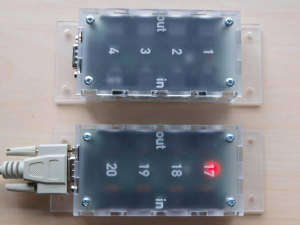
Because my Waldorf Midibay became too small for connecting all of my MIDI equipment, I went ahead and designed my own MIDI matrix / programmable patchbay. The modular MIDIbox Matrix has up to 56 input and 56 output ports and provides a smart solution for the fact that not all MIDI equipment is usually located in the same rack or corner of the studio space. MIDIbox Matrix features break-out boxes (BOBs) that give access to 4 MIDI in and 4 MIDI out ports at a time. These are connected via 9-pin serial cables to the main unit and are designed to be conveniently placed in the back of your rack, e.g. attached to the inner sidewall of a rack enclosure with screws or velcro tape. This means that instead of running 8 MIDI cables to the MIDIbox Matrix in order to connect four synths, you only need a single, cheap serial cable from your side rack to the center point of your matrix. Two BOBs each connect to a single I/O board, which does all the level shifting and signal refreshing. Up to seven I/O boards can be attached to the heart of the MIDIbox Matrix, an FPGA-based switching and routing logic that is controlled via a core board such as the STM32 or the LPC17. As the system is highly modular, it is possible to start with a low port count (4) and then increase the number of available ports by simply adding I/O boards and BOBs as needed. Fully loaded, i.e. offering 56 input and 56 output MIDI ports, the MIDIbox Matrix consists of 1x FPGA board 7x I/O boards 14x BOBs plus a core board and the PCB holding the user interface. This is how a BOB looks like in my setup: Software-wise, this is almost ready - everything works as expected, just the PANIC button has to be implemented in the next weeks, and some code cleanup will be necessary. You can find more documentation in the Wiki if you are interested. Kind regards, ilmenator
-
Mouser has them.
-
Well you will only find out if you take a look at your PCB and see if those sockets are there, or if the capacitors are soldered... :smile:
-
This is a SammichFM, not SammichSID - no SID chips at all on this one!
-
Sure, soldering is no magic! There are plenty of instructional videos on Youtube and such, both for soldering and de-soldering. If you only need to desolder a few components, a Hakko de-soldering station is probably overkill. Copper braid (also called de-soldering braid) in conjunction with a decent soldering iron will do the same job at a much lower price tag. However, my de-soldering station has turned out to be one of my better investments for this hobby... With respect to soldering, if you can afford to: make sure that you buy a temperature controlled iron with a fine tip.
-
MB-SEQ V3/V4 Control Surface PCB and matching case
ilmenator replied to Wilba's topic in MIDIbox SEQ
Necrobump alert! This thread is more than two years old and the info kind of obsolete. Go to Tim's (aka SmashTV's) webshop and order the PCB there! -
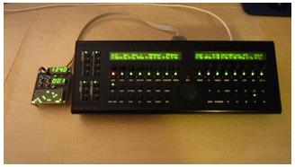
Hi, in the past months I have received numerous requests about providing kits for the TPD module from people having difficulties sourcing the parts individually. The TPD is the extension board on the left, read more about it in the Wiki. So, I thought I'd give that a try and provide a full kit. Kit price is 48 EUR plus shipping, and that includes all the parts necessary (and as listed in the BOM) for building the TPD and connecting it to the SEQ board. The only thing you'll need to add is a plastic knob for the rotary encoder - you'll probably want to match that anyways with the type you already use on the SEQ. If you want one, add a message to this thread or send me a PM, and if you provide me with your country of residence I can send you a shipping quote. Kind regards, ilmenator
-
Does Wilba's frontpanel support clickable encoders?
ilmenator replied to borfo's topic in MIDIbox SEQ
True - it looks as if they all connect to the same DIN - which means that the only thing you can do with the buttons is to activate a shift (encoder speed?) function. So it's probably not worth going for encoders with switches... -
Does Wilba's frontpanel support clickable encoders?
ilmenator replied to borfo's topic in MIDIbox SEQ
I'd suspect that they connect to the same DINs as the GP buttons right under the encoders - you could confirm this by tracing the pads' connections on the PCB, -
I am not 100% sure, but I think I remember that the program memory for the Ambika is absolutely maxed out (or was it on the Shruthi?). Also, Olivier has made it clear several times that he is not going to invest any significant amount of time into the Ambika anymore. It seems Mutable Instruments, his company, has moved on to other, more profitable items, leaving the DIY world mostly behind.
-
Hi, the LPC17 core board has now been superseeded by the STM32F4 based core - take a look at ucapps.de to read up. As this is also one of the STM32 family chips it might be easier to adapt to what you want to do?
-
There is no risk apart from the risk that it might not work. However, as the Ambika is DIY you could always include the merger in the Ambika itself and power it from there. Take a look at the MIDIbox range of mergers here.
-
I'd suggest that you immediately forget about this one - it will corrupt your MIDI data as soon as both devices connected to the IN port send data at the same time. Who on earth "designs" such things, without even considering the nature of the MIDI protocol?
-
You could check the datasheet of the PIC16(L)F88 for power consumption and then see how much power you can draw from MIDI. However, I would not rely on a merger without power supply - it is a failure prone system, as it will depend on the equipment you use it with whether it will work or not.
-
If you (or TK) wrote a modified driver this was absolutely possible.
-
Is that wheel color actually blue? I guess the "spare" knob (#17) is for the TPD extension? :thumbsup:
-
That's indeed an interesting price range! As far as I can see, these profiles are designed for 2mm strong aluminium panels. I think it could be an idea to actually use aluminium for the bottom and front, and have the top and back panel laser cut. I have access to a small manual milling machine, so I could still use 3mm acrylic and just mill a groove from behind along the long sides so that the panel fits into the profile. But then, doing the whole case in acrylic is probably as esthetically pleasing and sturdy as using these profiles...
-
How much do these profiles cost? Or the complete case you have in mind?
-
Yes, the MF NG can run stand-alone. Take a look at the module's description!
-
Panel thickness depends on components, even Reichelt has different ones. I usually go for 3mm acrylic. Engravings are not colored, but can be filled with paint afterwards. Screws are obviously not included in the Formulor/Ponoko order - how should they know what exactly you want to do with the lasercut parts??