ilmenator
-
Posts
2,305 -
Joined
-
Last visited
-
Days Won
37
Content Type
Profiles
Forums
Blogs
Gallery
Everything posted by ilmenator
-
I don't know because I haven't tried. Having a full range of colors was not in my focus - I was interested in getting the basic three colors, which works nicely (the photos don't quite do it justice). I might play around with this if I find the time, or someone else does this (I have some boards left).
-
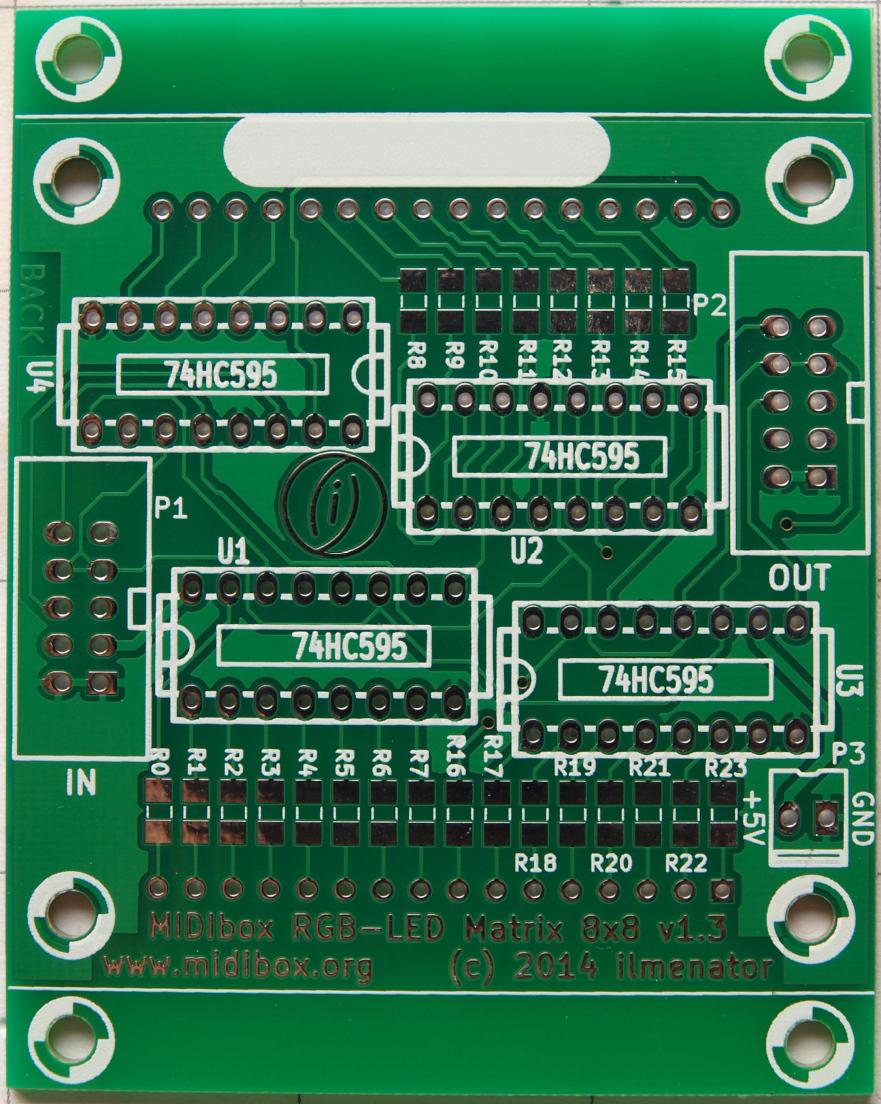
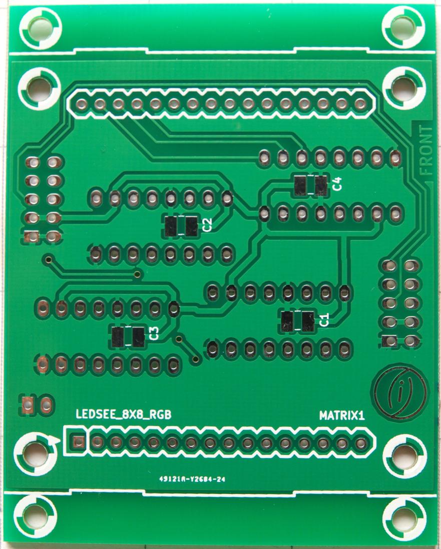
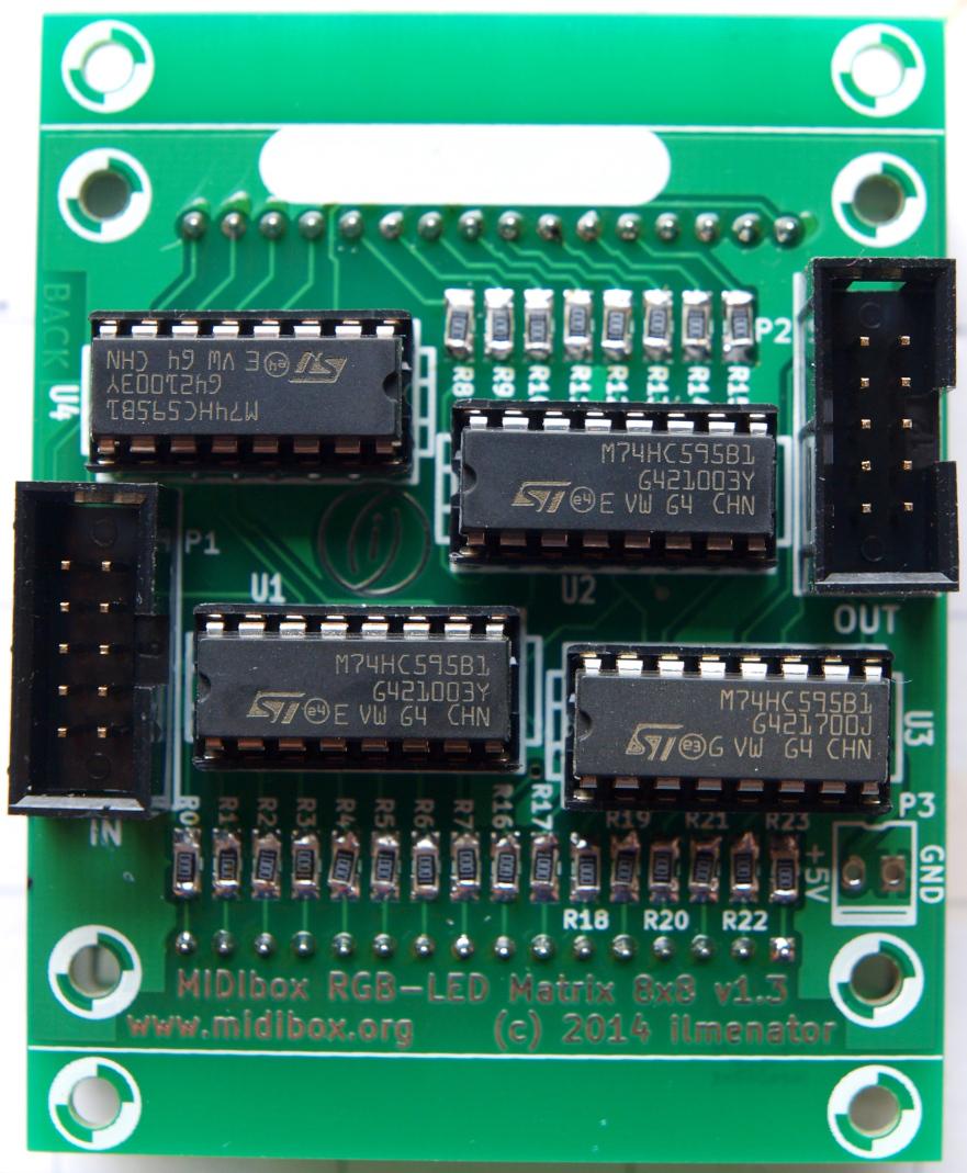
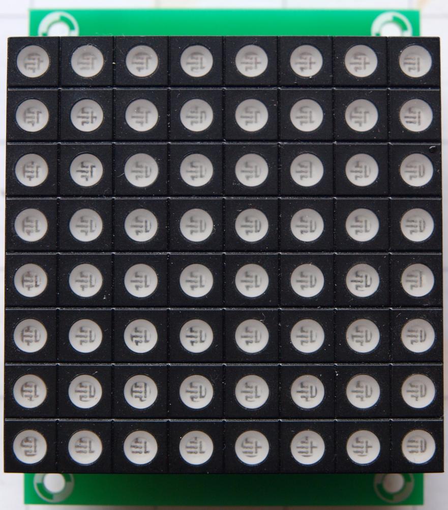
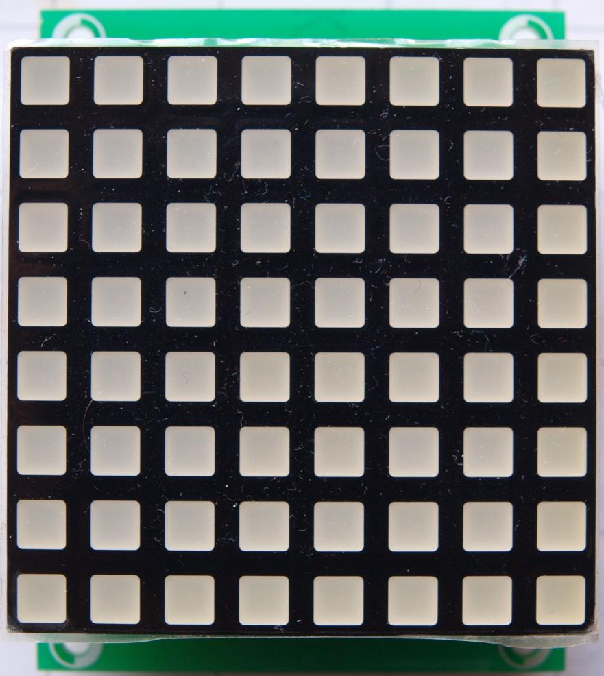
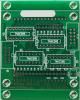
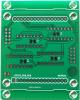
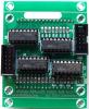
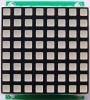
The RGB LED matrix described here can be used to signal feedback to the user, as for example in my MIDI Matrix with 56 Inputs and 56 Outputs. But, it can also be used for fancy stuff, Vegas mode, bling, impressing your neighbours,… The PCB is as wide as the RGB LED modules themselves, with enough space above and below for mounting holes. This means that the modules can easily be chained horizontally in order to create type crawls. If you cut off the top and bottom mounting holes along the line that is printed on the PCB then you can also create larger screens extending in two dimensions. It consists of 4 DOUT shift registers (74HC595) that feed the RGB LED display module in a matrix style. It is connected to J8/J9 of the core board. In order to access the RGB LEDs, use the BLM-X module which makes it straightforward to access single colors / single LEDs in the matrix. A fully detailed description of the project can be found in the Wiki.
-
Mine! PM sent.
-
One last PCB left.
-
Very useful report, thanks a lot!
-
Hi Tony, welcome here! For buttons you will need a DIN module, for LEDs you will need a DOUT module. I'd suggest to go for the STM32F4Discovery board and its MBHP core board instead of LPCXPresso and MBHP_CORE_LPC17, because there has been a revision of the LPCXPRESSO by the manufacturer, in which the pin layout was changed, rendering the core board (almost) unusable. The new STM32F4 Discovery is also more powerful. Best, ilmenator
-
In the MB-6582 you can mix different SID chips, at least in pairs of two.
-
Very nice! I guess the size of the PCBs fit a modular synth panel - is that 5U?
-
So what was the problem?
-
Upload .NGC file to Wiki not possible
ilmenator replied to novski's topic in MIDIbox Documentation Project
I don't think it is a good idea to make arbitrary file extensions available. It's a better idea to zip the file, and include a good description of what it actually is in the same zip file. -
I am using a Traco in my MB-SID 6582. I have nothing to complain about :smile: .
-
You create a link to a page that does not yet exist and then follow it by clicking on it. Best, ilmenator
-
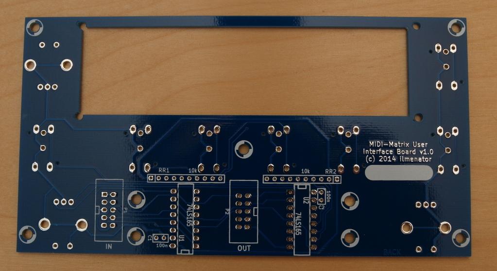
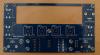
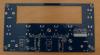
Hi all, as a by-product of my latest project, the MIDIbox Matrix (a MIDI router with up to 56 in- and out-ports), I have created a PCB for the Standard Control Surface or SCS. This little board assumes that you are using a 2x24 character LCD and 4 items per menu page. This is slightly more character space per menu entry than what TK is using, however the code is fully configurable to handle this. Personally, I find the 5 available characters per menu item much more comfortable and less cryptic than lower character counts. Assuming that you want to use both shift and exit buttons for navigating the menus, the board is prepared for one extra button to the left of the display. Also, two additional encoders (with push function) can be used - but these can also be left out, obviously! Specs of the PCB are documented in the WIKI. I have 4 of these available, but would be willing to order more if there is enough interest. Asking price is 13€ per board, plus shipping costs. Drop me a PM or answer in this thread if interested. Best, ilmenator
-
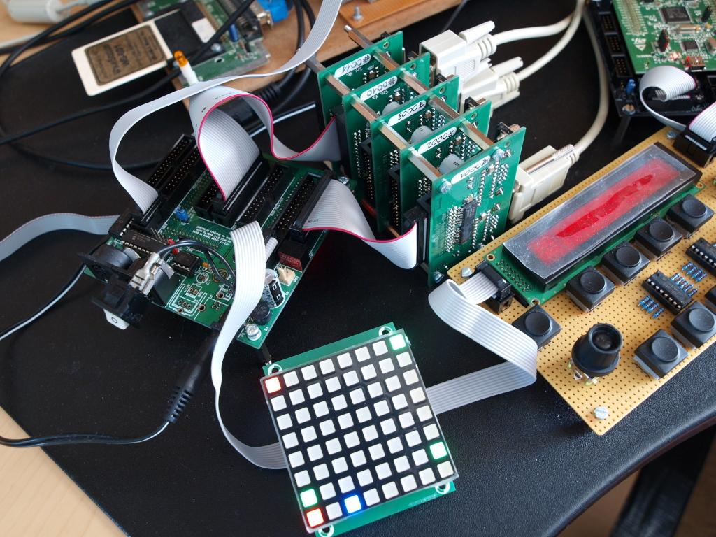
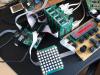
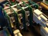
Just a few more impressions of the system so far - the UI is still on veroboard, but the proper PCB should arrive this week. The I/O boards are stacked and just low enough to fit in a 2U rack case. You can see two versions, on the left the first prototype v1.0 (2x), on the right (3x) v1.1 with angled headers and a slightly different layout (but identical functionality). The MIDI activity display fits in a 2U frontpanel, as well as the UI (not the one on veroboard shown here).

-
As always, very nice! It seems you have found your personal sound, the piece is easily recognizable as a Hawkeye composition! Where exactly did you shoot the video?
-
If you run the latest version of KiCAD (on Windows, by using KiCAD Winbuilder), the new realistic renderer is already part of the package. Also, check out the new (manual) router and its different modes. It is brilliant!
-
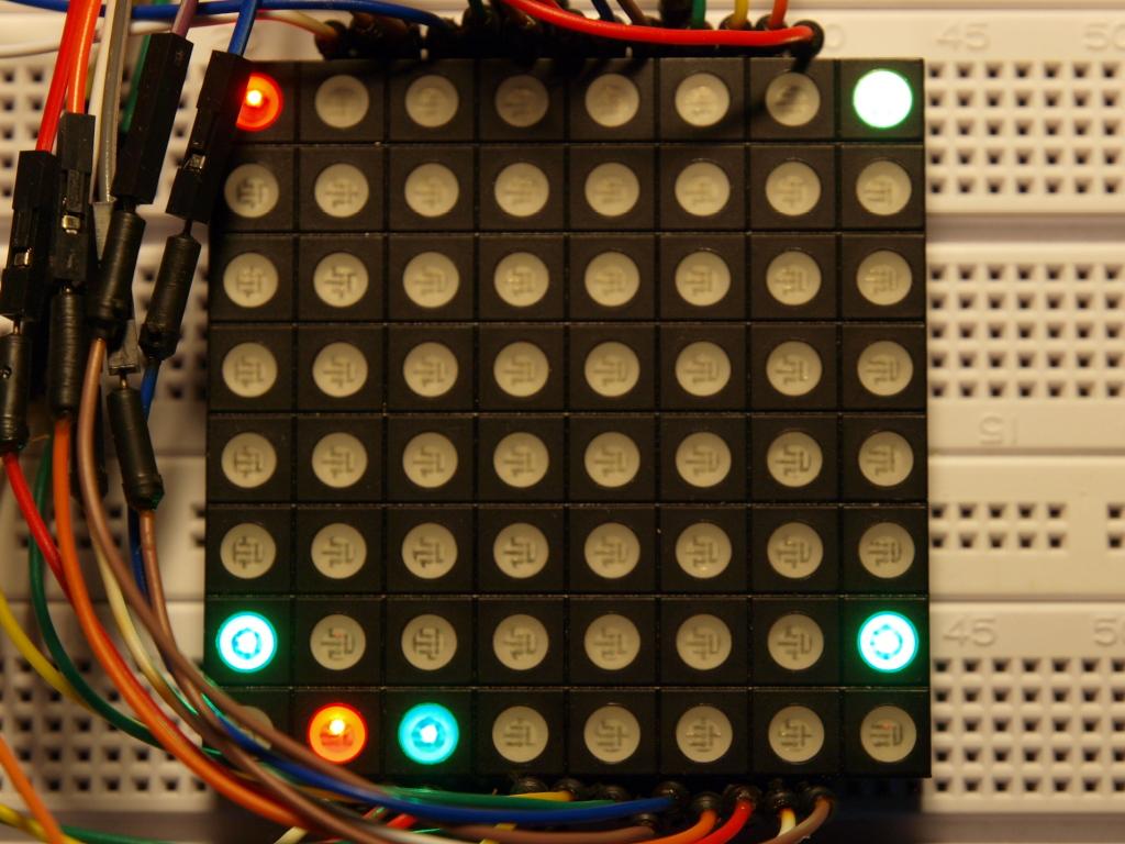
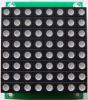
So after all I went with the RGB LED Matrix module to indicate MIDI activity on the 56 in-ports (red) and 56 out-ports (green) in the upper 7 rows. The lowest row displays MIDI merger activity, the two inputs of Merger 1 on the first two LEDs in red, and its output on the third in green. The same goes for Merger B on the following three LEDs. The last two LEDs in the last row are not involved for now. Also, I'll have to think of what to do with the blue color... In the picture you can see that a MIDI signal is coming in on port 1, which is then forwarded by the Matrix to ports 8 and 49. It is also forwarded to input B of Merger 1 (red LED in the lowest row), which then passes it on to its output (green LED next to it), which is connected to MIDI out port 56 (green LED in the lower right corner). I have the RGB LED Matrix module working on breadboard for now, proper PCBs are on their way and should arrive next week or so. Apart from a little code cleanup, the Config page in the menu, and a Panic function, everything I wanted in this router is functional by now. :happy:

-
I am not on XP anymore, but have you tried a format like this: /J/mios32/trunk instead of J:\mios32\trunk ?
-
[SOLD] Midibox kits / components / LCDs / cores / MF
ilmenator replied to findbuddha's topic in Fleamarket
Wow, $300AUD is a steal - if I wasn't living on the opposite end of the world this would be mine. -
They are voltage regulators - there are a number of different options for powering this beast, so if they are not installed in your synth but the machine runs fine there is nothing to worry about!
-
Grab a small screwdriver with your right hand, insert the blade into the contrast pot, and perform a rotary motion :-)
-
Mein Reden... Aber Platinenplatz ist hier wohl wichtiger. Die Designregeln beschreiben uebrigens nur die Minimalwerte - kleiner wird nicht akzeptiert, eben weil dann die Ausschussrate inakzeptabel hoch wird. Die Designregeln haben aber nicht unbedingt was mit "best practices" zu tun. Das merkst du spätestens bei der Fehlersuche.
-
Dieses Routing sieht doch viel sauberer aus! Allerdings bist du wohl ziemlich nah dran an den Minimal-Eckdaten deines Leiterplattenherstellers - die Leiterbahnen sind sehr schmal und liegen sehr eng beisammen. Damit erhoehst du die Fehlerrate deiner Boards.Vielleicht geht da ja noch was mit ein wenig mehr "Trace-Tetris"? :thumbsup:
-
Sounds interesting! Which EZ-Kit board are you using?
-
Autorouting? Lass die Finger davon und mach es selber! Das Ergebnis wird allemal besser als das, was in dem Screenshot zu sehen ist. Warum sind deine DIN-Module eigentlich separat von den Encodern/Tastern, also dem "User Interface Board"? Wenn ich schon ein neues Design mache, dann würde ich doch versuchen so viel wie möglich zu integrieren - die Antworten auf meine Vorschläge deuten ja an, dass du eh einen sehr speziellen Anwendungsfall hast?