ilmenator
-
Posts
2,305 -
Joined
-
Last visited
-
Days Won
37
Content Type
Profiles
Forums
Blogs
Gallery
Everything posted by ilmenator
-
Oh, one more thing: you might be interested in how the Mackie C4 Pro handles text display on any of the four screens - I would think that Mackie Control and Control Extension use a very similar protocol. Some years ago I uploaded the MIDI implementation, you can find it here.
-
On the old 8-bit core, I had implemented this to work like this (just found an old document detailing the mechanism, I don't remember exactly whether the application was a custom made one, or whether this was supported by all MIDIboxes - this is just to say that what you want is definitely possible): LC Display Text can be displayed on the LCDs by sending MIDI System Exclusive (SysEx) data to the MIDIbox. It can receive encapsulated ASCII strings from the host and display them on the LCDs. Assuming two LCDs present, the first line of display LCD1 is reserved for displaying such messages. The MIDI SysEx string for displaying text must look like this: F0 00 00 7E 40 00 08 01 00 00 text as ASCII data F7 The first byte indicates that the following bytes are SysEx data. The next eight bytes are a unique identifier which tells the MIDIbox that the following data bytes contain text to be displayed on the LCD. The first data byte (the tenth overall byte) determines the cursor position of the text to be displayed. The remaining data bytes contain the actual ASCII encoded text. The last byte (0xF7) indicates the end of the SysEx message. Assuming the first display to have 2 x 40 characters, text to be displayed on LCD2 would then need to start at cursor position 0x50 (80 decimal). For the Core32 you might want to look at the corresponding display functions here. Edit: Okay, TK was faster, and looking at his reply it was probably some custom code that I used. About eight years ago, don't remember all the details...
-
Beta Test: MIOS32 Bootloader v1.009 could solve USB issues under Windows
ilmenator replied to TK.'s topic in MIDIbox SEQ
Now that is really good news! -
Interestingly, I just saw that most of my old PCB-mount MIDI connectors have two holes underneath, so if you had the respective holes in the PCB you could use two screws to secure the connector to the PCB. I checked with the newer ones that Reichelt sells, and these do not have the extra screw holes. What a pity.
-
That is actually kind of the MIDIbox mantra: read, read, read, then read some more... not always easy to convey to newbies without sounding bigheaded, though :whistle: .
-
With my Formulor.de order there was no backing paper on the P3 size panel (which the MB-6582 case was done from). However, I had two other P1 size items in that same order which had a plastic foil on both sides, the smooth and the rough one. Maybe I was just unlucky with the P3 panel.
-
At least with Formulor.de I can confirm that they are all there, no problem - they do not know what is the beef and what is the bone, after all. Here is the result: When I did this I was inspired by

-
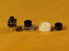
A set of laser-cut and -engraved buttons.
-
-
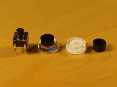
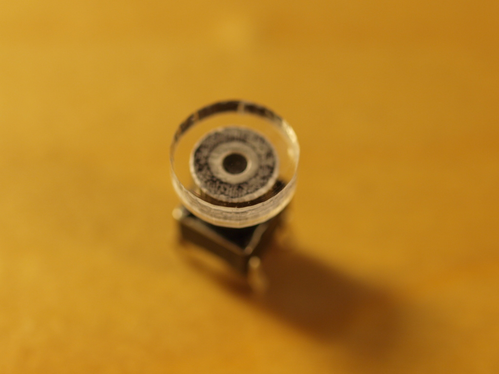
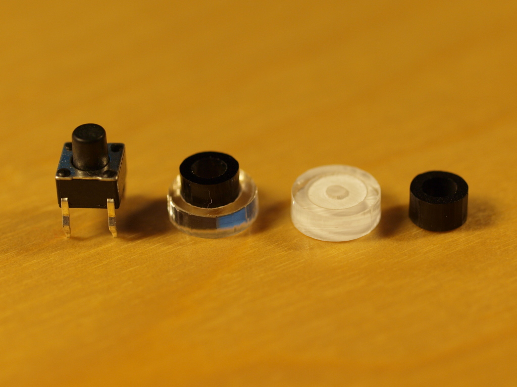
From the album: ilmenator - button caps
The single parts - black "ring" for stability (far right), transparent top with engraved groove to hold the ring (center right), ring and top glued together (center left), and button stem (left).© 2012 ilmenator
-

-
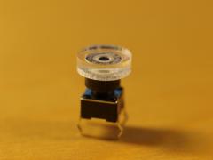
From the album: ilmenator - button caps
Cheap button that can be illuminated from underneath, made from laser-cut and engraved acrylic panels.© 2012 ilmenator
-
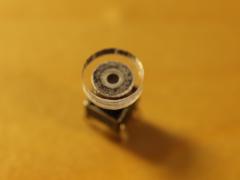
From the album: ilmenator - button caps
Cheap button that can be illuminated from underneath, made from laser-cut and engraved acrylic panels.© 2012 ilmenator
-
Altitude, did you leave the paint to dry before you wiped off the excess with thinner?
-
I would think so, yes. The LED schematic is here, also with some vacant slots.
-
I could not say that I need them, I have a backlog of things to build where I could not use these anyways, and I already have way too much stuff sitting here waiting to be used. I rather see a lot of interesting opportunities after having lasered my first Ponoko panels and seeing how easy this is and how cheap compared to all the other guys working with / offering aluminium front panels. Until now I have always restricted myself to round button caps, because they were easy to drill. That limitation seems to be gone now :frantics: .
-
All engravings are heavy raster only, the vector letters were converted into raster letters according to the instructions on the Ponoko site. I had my panels made by Formulor.de, and there was no backing paper attached to the panel. The only thing that was there was the huge sheet of self-adhesive paper they stick on the already lasered panel in order to remove the stuff from the laser table. So yes, there was a little frustration at first. In the end, I was trying to be really careful, only filling two or three letters at a time, removing excessive paint with a cotton bud soaked in thinner, and then remove the residue with another cotton bud soaked in isopropanol / isopropyl alcohol. The thing is that you need to be fast with the last step, because once the thinner has dried up the residue can only be removed with more thinner, but not with the alcohol. On the other hand, if you get too much alcohol into the paint-filled engravings, then the filling will look bubbly and not evenly distributed after drying. I think for kits that are produced in numbers, a Lexan overlay is the perfect solution. For a one-off, it's a bit expensive...
-
Interesting! Where did you get these button caps from? Now that I discovered Ponoko I am no longer limited to round holes for buttons :frantics:
-
Personally, I never liked the ALBS knobs too much. They do look kind of cool, especially the transparent ones when they are illuminated from underneath, but their shape doesn't feel right in my fingers.
-
Well, my bad - the schematic I linked above is actually for the MB-6582, and not for the MB-SEQ. :whistle:
-
If you are refering to the MB-6852, I would say it is very well documented and might take a bit longer because it has more components, but is not necessarily more difficult to build. PCBs and semi-kits are available from SmashTV, as well as most other components necessary.
-
The firmware is proprietary and undisclosed, and Ploytec only sell the complete chip, programmed. I'm not even sure it is programmed / flashed in the traditional sense, or whether that is a mask programmed / factory programmed variant of the chip.
-
I have one more PCB available, and I can provide a set of buttons if needed for cheap (but you can also just have the PCB if you prefer that). I'll travel to Germany middle of December, which would make shipping (also international) reasonable, even with tracking/insurance (which I would prefer). PM me if interested.
-
I'd suggest you look at the schematic, not the board layout. That is much easier to grasp :smile:. Edit: Sorry, I just realized that this schematic is for the MB-6582, not the MB-SEQ.
-
Has there been any discussion somewhere about using FSRs in a dynamic way, i.e. actually reading their "velocity" values? Via the AIN?
-
Just out of curiosity: how far will it travel?