ilmenator
-
Posts
2,305 -
Joined
-
Last visited
-
Days Won
37
Content Type
Profiles
Forums
Blogs
Gallery
Everything posted by ilmenator
-
[solved] Sammich Bank Sticks problem [bad PSU & solder work]
ilmenator replied to Shiftone's topic in MIDIbox SID
What MIDI interface are you using? -
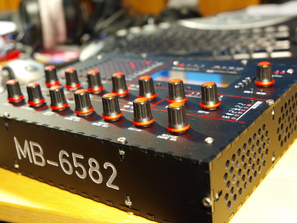
Well that's a bit hard to say, because I had a larger panel to cut for which I had to choose Ponoko's P3 size. Then I simply placed the MB-6582 parts on the leftover space. This way, there was no material costs for it. The total panel was around 134,- Euros, with most real estate and complexity dedicated to the other elements. I think Ponoko's P2 size should account for a complete case, and the cutting and engraving is probably around 50,- Euros or so. I could try to separate the two designs and get a price quote for the MB-6582 alone if there is interest. If you left out the large "MB-6582" engraving in the front and chose straight ventilation slots instead of the honeycomb structure in the side panels it would become even cheaper. The funny thing is that I actually detected a flaw in Ponoko's pricing algorithm, reported that, and got a discount. In order to make the panel as cheap as possible, it is currently required to follow a strategy in which you "draw" those cuts that are close to each other in a proper sequence. I.e. for example starting at the top left, and then going right and down and left again, filling the panel in a single "macro-motion". The worst thing you can do is to "draw" all the mounting holes first, then the LED holes, then the tact switch holes, then the encoder holes. The problem is that Ponoko's pricing algorithm will determine the laser's motion according to the EPS file structure, and that in turn is defined by the order in which you added the cuts originally. They told me that they would be re-working their algorithm, but that it might take a bit of time before the changes were actually implemented. Yes, and you are also quite surprised when you hold it in your hand for the first time - this thing is heavy and does not feel like cheap plastic at all!
-
Will the MIDIbox64e build work for a keyboard controller?
ilmenator replied to Dreadknot's topic in MIDIbox HUIs
Among other things it will hold a config file which tells the core what is connected to which of the DIN / DOUT shift registers. -
It's actually a good idea, I think a lot of people could benefit. The Ponoko frontpanels can easily compete with aluminum ones, especially as they are usually not so large and stability/bending is not a big problem. However, it's not necessary to create a tutorial, there is a lot of information around already: 1. If you just go to the Ponoko website you can find a number of good hints. 2. Over at the Mutable Instruments forum you will find a very nice and useful tutorial from schrab(ikus). 3. For the notches of the case, go over to rahulbotics and enter the dimensions of the case. The notches will be created automatically and you get a PDF which you can then use as a basis for your design. Just do it - start with something easy before you go for an expensive panel.
-
Well if you plan ahead it's actually quite easy. I stuffed the LEDs loosely and then mounted the PCB to the frontpanel. Only after that i pushed the LEDs into place one by one and soldered them. One leg first, then make sure all of them sit flush, and then the second leg.
-
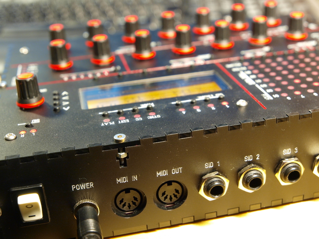
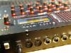
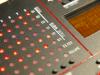
So I finally got round to finish my MB-6582. Channel 3 is still silent, but I guess I will be able to fix that - didn't have the time to look into that yet. The case is a Formulor/Ponoko case, with flat top LEDs (I do not intend to ever separate the upper PCB from the front...) and a plexi window for which i milled the grooves manually. Happy here! :frantics:


-
Joeri, are you also located in Sweden like strophlex?
-
Control surface PCB for 16 encoders/LEDrings Bulk Order
ilmenator replied to Fairlightiii's topic in Bulk Orders
That you'll need to do yourself: look at the first message in this thread and follow the instructions closely. -
Yes, that is feasible, but cable length on the "serial bus" might be an issue. It's simply a matter of trial and error to see how long a cable you could use. With proper shielding and termination it should become practical, though - there are a few threads about termination in this forum somewhere, use the search. Also, the BLM accessory will most probably be located very close to the SEQ... However, you might have to switch between two hardware config files then, depending on whether the accessory is connected or not. I am not sure what happens if you have defined the BLM shift registers but don't physically connect them?
-
Can't afford no shirt? :shocked:
-
Hehe, I was not commenting on the paying, but on the writing (bragging?) about it. To me it seems more than obvious that you pay the stuff that you buy from someone, so I was wondering why the heck everybody has to announce it here?? :flowers: :tongue:
-
I'm not TK, but yes this is the BLM that is supported in the MB-SEQ, and that is not recommended for MB-NG based MIDI controllers. Just in case anyone needs a BLM for their MB-SEQ, have a look it looks as if I had one set consisting of PCB and buttons with caps left.
-
I would think that nILS probably notices that himself, and will check his Paypal account balance anyways, regardless of what you write here :rolleyes: . edit: fixed a typo
-
Es werden noch mehr kommen :thumbsup: Zum ersten der Kette. Allerdings beinhaltet die "Kette" (also das Kabel) ja sowohl die seriellen Signale für DIN als auch für DOUT, die Situation ist also ein wenig komplexer als es auf den ersten Blick scheint. Die Daumenregel lautet aber einfach: versuche, das erste Flachbandkabel (und alle weiteren) so kurz wie möglich zu halten. Bis ca. 40cm ist das alles kein Problem.
-
Control surface PCB for 16 encoders/LEDrings Bulk Order
ilmenator replied to Fairlightiii's topic in Bulk Orders
Sorry, I did not remember Tim's comment. Obviously, everything is under control, that's very good :thumbsup: . -
Control surface PCB for 16 encoders/LEDrings Bulk Order
ilmenator replied to Fairlightiii's topic in Bulk Orders
Hi, I just took a look the the hi-res PDF layout - have you performed a design rules check (DRC) and resolved all errors? It seems that every other LED shows a marker that looks as if DRC had detected something? Also, I think that some of the tolerances might be a little on the risky side, e.g. with respect to distance between some tracks and ground plane. Your manufacturer might support those tolerances, but are you on a 0% failure rate guarantee? If not it might make sense to increase tolerances somewhat. Best, ilmenator -
Control surface PCB for 16 encoders/LEDrings Bulk Order
ilmenator replied to Fairlightiii's topic in Bulk Orders
Sounds reasonable to me, although I would probably put it MB-LRE8x2CS, as the LRE is the more important info compared to the 8x2 "form factor". Also, I think we had the BLM 16x4, for which the number of columns were mentioned before the number of rows. -
Ich habe weder mit dem neuen noch dem alten AIN eigene Erfahrung. Allerdings erscheint es mir extrem unwahrscheinlich dass die Leitungslaenge kritisch sein soll fuer alles was unter einem Meter liegt. Viel eher vermute ich, dass die Leitungsfuehrung zu Problemen fuehren kann (Einstreuungen von Netzfrequenz), oder dass die Massefuehrung in den angefuehrten Beispielen problematisch war. Ich wuerde auch hier erstmal auf Flachbandkabel setzen.
-
Wenn nicht alle LEDs gleichzeitig an sind sollte es keine Probleme geben - falls doch dann könntest du noch Treiber einfügen. Die Frage ist letztlich, wo der Aufwand größer ist bzw. wie viel LEDs du insgesamt brauchst. Solange die DOUT-Kette nicht zu lang wird spricht erstmal nichts gegen das direkte Ansteuern von LEDs (ohne Matrix). Kabellängen und -querschnitte sind für die digitalen Signale (also von Taster und LED nach DIN und DOUT) unkritisch. Allerdings sollten die seriellen Leitungen (also vom Core zu den DIN/DOUT boards und zum AINSER64) so kurz wie möglich sein. Unter 40 cm bist du auf der sicheren Seite. Länger funktioniert in der Regel auch, muss aber nicht. Normales Flachbandkabel ist tausendfach bewährt :-).
-
All respect to Wilba, but I don't agree with this statement - not soldering the large tabs allows the encoders to wiggle around on the PCB when turned (unless they are fixed to the frontpanel). This is not good for the active pins and their solder joints. The tabs are there for a reason.
-
This could help even if you are going to use a plastic enclosure!
-
The link that TK provides in the first post of this thread provides the answer to that question already:
-
Schau dir mal die "alte" MB-SEQ Button/LED Matrix an, da siehst du auf der linken Seite die Schaltung fuer die Taster, und auf der rechten die fuer die LEDs. Nicht verwirren lassen, rechts sind Duo-LEDs verschaltet, also zwei LEDs in einem Gehaeuse, die sich die Kathode teilen. Aber das Prinzip sollte aus obigem link eigentlich klar werden, und auch hier gilt: Solange die DOUT Ausgaenge, an denen die LEDs haengen, das gleiche Potential haben, passiert gar nichts. Sobald Strom fliessen kann, weil ein Ausgang auf logisch "high" und einer auf logisch "low" steht (und die LED richtig herum angeschlossen ist), leuchtet es.
-
Here is the BOM for populating the PCB. Please note that there is no silkscreen on the back side of the PCB. However, each IC has its reference etched in copper next to its footprint. Also, pin 1 of each IC is clearly marked with a "1" next to the corresponding pad, and all 100nF smd capacitors (C2-C7) sit close to the ICs. BLM BOM.pdf
-
Die Dioden sind Standard 1N4148 Typen, keine LEDs. Sie sorgen dafür, dass Strom nur in eine Richtung fließt, was in der Matrix-Verschaltung wichtig ist, weil sonst nicht eindeutig wäre, welche Taste gerade gedrückt ist. In der zitierten Schaltung "sieht" ein DIN-Eingang lediglich, in welchem 8er-Block eine Taste gedrückt ist. Welche das genau ist kann nur ermittelt werden wenn man weiß, welcher der DOUT-Ausgänge gerade aktiv ist. Damit die benachbarten Ausgänge im selben Block nicht auch aktiv werden gibt es die Dioden. Falls du auf OSC verzichten kannst brauchst du in der Tat keinen MagJack. Der ist rein optional.