

Smithy
-
Posts
1,240 -
Joined
-
Last visited
-
Days Won
28
Content Type
Profiles
Forums
Blogs
Gallery
Everything posted by Smithy
-
REGISTANCE IS FUTILE!
-
o_O Dude you're not meant to be awake! Go haz some sleepz nao plz! You must be too excited from building all day! I know the feeling.
-
I haz made Knob Removal tool, in case you fuck up after you have finished mb-6582, e.g. ribbon cable breaks or whatever. Cut a rectangle/square into a piece of plastic card, like a credit card or whatever. Make sure the notch is about 7mm wide to fit around the shaft of the encoder / pot. Slide it under the knob, and lift it off. This way helps prevent marking the panel. Told you i wouldnt have anything worthwile. :wink:
-
I recommend you use flat washers in between the spring washers and the screws that go into the threaded spacers for the CS. The spring washers on their own tend to eat up the lovely gold plates on the PCB, im wishing i used flat washers now. Just adding that tip here so i dont post in the middle of your guide for the CS Construction. If i can think of any worthwhile tips ill post them here. ;)
-
 Beautiful. and btw: kthxbai
 -
Those look a bit big alright, i ordered these ones which were posted in the "Killed CS thread", they have a shorter connector: http://www.reichelt.de/?;ACTION=3;LA=2;GROUP=C1442;GROUPID=3224;ARTICLE=32346;START=0;SORT=artnr;OFFSET=16;SID=32mZJE3awQASAAAHg@5Ood0868d254968150e47f106737357f08f Or from Conrad: http://www.conrad.de/ce/de/product/741256/PLATINEN-STECKVERBINDER-8-POLIG
-
Excellent work! Took me about 3 years to get that far ;). I notice you have SIL headers on the base board, for where the CS will connect. What connectors are you planning to use there? If you're planning to use the same connector thats used for the LCD, it will be too big, theres even less space to play with there, than with J15.
-
I had the same problem so i decided to order those cables from Conrad also. Ill have to cut one of them into a 2-pin version. The ribbon cables that didnt break, were very easy to pull off by hand.
-
One last thing i forgot to ask is if you put 90 degree bends at the end of the wires, or did you just solder them straight? The latter im assuming.
-
Woah! Youre are actually using cable twice as long, i overlooked the 6" in the description. Mine are just left than half. Thanks a lot for the pics, it looks like there will be a lot less strain on the cable doing it that way, at least where the ends of the wire are concerned. Thanks a lot for sharing the pics Dan.
-
HI Digineural, thanks for the reply! I'm using the same cable you described, ordered it from Mouser too. I would really appreciate the pics, as im trying to figure out how you tucked them in. I bought 10, already ruined one, and since I need 8 cables + 1 with only 2 wires for the 5v / GND, i dont really want to risk damaging the 9th one.
-
Are you using a c64 power supply for it, or just some other PSU with a DIN connector?
-
Thanks for the advice wilba. I actually tried it that way (after scoring the cable), but after seeing the marks i decided to stop. Should be fine this time.
-
Cant believe i'm almost there. In the CS guide it says to cut into the flat side of the ribbon cable. The problem is, that my ribbon cable is ribbed on both sides, and its almost impossible to strip the insulation without cutting into the wire as a result. The insulated piece is 50mm long, and the wires stick 4mm out on each end. which is a total of about 58mm. Would it be okay to solder it as is, or would it be too long? The guide does say that the perfect length would be 42mm to 43mm. The only other way i can think of stripping the insulation, is by pulling on the 8 wires with a long nose pliers, so the insulation slides back. And then cutting across the excess/overlapping insulation, and pushing the insulation back down the wires again.
-
I just finished soldering the LEDs and encoders, and was looking for a way of testing them. I never the current from a continuity tester would be strong enough to light an LED, it works like a charm. In the CS Construction Guide, it says to test the Power LED with a resistor value, in order to determine what value resistors you should use for LEDs on the PCB. Since there are more LEDs on the CS per resistor, wont the brightness differ to the brighness from the Power LED?
-
No problems, i was hoping it would be useful to somebody. The panel was fine, it just had the blobs of JB Weld on the back. I decided to sand them off, using sand paper, a dremmel would be ideal, but sanding paper was all i had. Half way through i flipped it over and there were quite a few light scratches on the front, possibly from epoxy debris falling between the front of the panel and the cardboard i had it resting on. So i decided to stop before i did more damage, and decided to use the first panel i received from FPD instead, (the one with the bad paint infill). The other one with the scratches will be going to nILS.
-
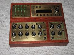 Wow, that is the most "vintage" midibox design i have ever seen. Its beautiful. Vintage SID would be a fitting name!
 -
Right, as i made a monumental fuck up in aligning the pcb with the panel, i think I better give a warning to people who are considering having Countersunk Corner Holes & Screws in their panel.. Bottomline is, that you should not use the 4 Screws to align the panel with the PCB, as they will not be perfectly perpendicular to the back of the panel, because they will have room to move around in the countersunk holes., (unless you're lucky) This is basically what happened: I put the 4 countersunk screws through the holes at the front of the panel, and i used a spring washer and nut on the opposite side of each screw, to lock them into the back of the panel. When trying to mount the PCB, i realized that it was easy to get 3 screws through the holes of the PCB, but it was tricky to get all 4 screws through the holes. Looking back now, this was a warning sign that the screws were NOT perfectly aligned / perpendicular at that time, but i assumed i was not holding the pcb perfectly horizontal while trying to drop it into the screws. I also used 2 additional nuts per screw, each were either side of the PCB to hold it in place. And i inserted some switches as directed by the guide to help with the alignment. It was only after the 24 hours of applying the weld, and clamping the pcb and panel together, that i realized the shafts of switches were pushed a bit diagonally. This was because the threaded spacers were between 0.5mm and 1mm too far to the left of the back panel (out of alignment), and the switches (being the weakest) were forced to the side. What i would recommend from my experience, is to not use the screws to align the panel and pcb, but to actually solder the switches first and use the switches to align them. Obviously before you solder the switches to the PCB, be sure to mark off where the standoffs go on the panel, as stated in the guide. You will have to be extra careful not to push a Switch into a blob of JB Weld, in particular the button for SID L R, as that is the closest switch to a standoff. Remember this is only for people using countersunk corner holes/screws. Might be a better idea to use non-countersunk holes and button head screws, as they should be perfectly perpendicular to the panel. Or even better use no holes at all, and weld the 4 screws to the back of the panel as Wilba did in the guide.
-
Can i haz 10 chipz with mah cheezburger? kthxbai
-
 Dude whats the poster on the right? Im itching to see the rest of it!
 -

MIDIbox of the Week (MIDIbox Seq v4 by gjvti)
Smithy replied to gjvti's topic in MIDIbox of the Week
Beautique! hehehe. -
Wow man thats awesome! I am insanely jealous. I thought a panel would with a commodore logo would be cool, but i never actually thought of adding it myself, i didnt think there would be enough room. If a tribute mb-6582 was ever built for Bob Yannes, it be cool to get one made up with his signature.
-
Yep, I have a 1.5mm Panel. It looks fine, holds the screws in place perfectly. Some peeps in the chat think its a bit risky, but the countersink looks substantial enough to my eyes. I cant see the screw breaking through it. You could always go non countersunk if it makes you feel happier. Im close to the JB Welding stage now, i will probably do it tomorrow when i feel more alert. If you would like me to take a close up shot of the countersunk holes i can. Im an FPD noob, so I dont know if you can copy and paste the dimensions of the hole as well as the hole itself, but those dimensions were spot on. The dimensions are the exact same as the holes shown in the Pactec PT-10 diagram of the panel. (the pdf file) Theres a pic of it in the other thread, and wilba confirmed the dimensions in his post.
-
As it says on that page: "Also, it should be noted that due to a rule in the software, you cannot always specify 1.5mm panels over a certain size, so the frontpanel has 2.0mm specified in the file and a note that thickness should be 1.5mm. Be sure to confirm in email you want 1.5mm thickness when ordering, as they can and do make panels of this size in 1.5mm aluminium, with engraving. If they say they don't, I will personally remind them that they do." in the note section of the checkout program, just put in something like "*NOTE* Panel must be 1.5mm thick." if its not already added. The program doesnt let you select it, but schaeffer DO make them with 1.5mm thickness if you like!
-
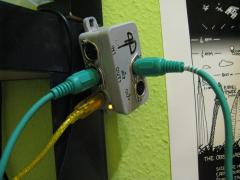
Ooops! I just realized now that this jack is too big to fit the standard size hole on the mb-6582 back panel. The solder points / holes are tiny also. Luckily i had one in my older sid build that fits.