latigid on
-
Posts
2,524 -
Joined
-
Last visited
-
Days Won
149
Content Type
Profiles
Forums
Blogs
Gallery
Everything posted by latigid on
-
Thanks, seems to be working now after removing device/disabling and other fiddling. The ploytec wouldn't progress past the "connect your device now" without a proper GM5 I guess.
-
Sorry, not sure exactly what you mean? I will order a batch of miniCore boards to go with the BLMs, or if you prefer you can use a regular Core8 as the circuit is identical (linked above). It's just less convenient. The 125 chip simply buffers SO, SC and RC and there's even extra buffers on the main PCB. Probably neither of these are necessary now we know more about the brown out reset behaviour.
-
Exactly, you should instead disable the unused DINs and build a new .hex file otherwise the PIC is looking for registers which aren't there!
-
Did you compile a new setup_midibox64.asm file? Can you post it?
-
Relevant in setup.asm Is this correctly done?
-
I don't know much about MB64, but if the number of shift registers configured in software is greater than what you have installed I can imagine their addressing could get messed up. Feel free to post a pic, that always helps.
-
Salut Pierre, Here are the schematics; http://www.ucapps.de/mbhp/mbhp_blm_scalar.pdf -- SCALAR module which is just a mixed DIN/DOUTX3 board. There are a few modifications such as enabling a power on delay and B-E resistors for the current sink transistors. Five of these are integrated into the BLM PCB. http://www.ucapps.de/mbhp/mbhp_blm_map.pdf -- this is the matrix routing for the buttons and LEDs. http://www.ucapps.de/mbhp/mbhp_core_v3.pdf -- this is the 8 bit Core of which unneeded headers and the LCD driver circuit have been removed for the miniCore. There's an extra line driver implemented for the digital signals, and the MIDI I/O and power come in on the same 2x5 DIL header. Best,
-
Just to correct you there hawk, the resistors are pull ups to +5V. The other point to check is if resistor networks are oriented with the dot aligned with the PCB silkscreen. If this is a DIN kit from SmashTV then you have the correct components. Something else to consider is that DIN (or DOUT) modules will not cascade unless all chips are installed because the specific SI or SO data signal is routed through each subsequent shift register.
-
http://www.mikes-elektronikseite.de/ Funnily enough I don't think my Quad IIC is working either. I wonder if the 16Fs I bought from Mike aren't bootstrapped because I didn't ask by default...
-
Sign up here
-

MB6582 build. Issue with 12V 6581 sids chips
latigid on replied to dreamer's topic in Testing/Troubleshooting
As far as I know this the (in)famous VCA issue inherent to SIDs -
"Upgraded" forum complaints/suggestions
latigid on replied to latigid on's topic in MIDIbox Documentation Project
Okay, I went to the beginning of time and it's fixed. Many thanks! -
"Upgraded" forum complaints/suggestions
latigid on replied to latigid on's topic in MIDIbox Documentation Project
Works properly in M$ Edge thingee but not in Chrome. No difference if I close/empty cache etc. It's not a big deal, just strange! Thanks for the help, -
Is there a public source for those drivers?
-
"Upgraded" forum complaints/suggestions
latigid on replied to latigid on's topic in MIDIbox Documentation Project
You can always get the image back by clicking the "lightbox" icon. Meanwhile, my interface is still a bit funny: The icons are shifted one over while the centre and left align buttons are for and
-
Windows 10 recognises the SEQ (STM32F1 Core) and its four USB ports but communication over MIDI in MIOS Studio isn't possible. I think it was working fine with Win8. An old Win7 machine works fine and recognises the ports as "GM5 Port 1-4". I can't spend much time fixing this for the next few weeks, but I thought I'd put it out there if somebody already knew of a quick solution.
-
Is that the schematic for the SEQ or something else? The SEQ is connected in a matrix. From the layout data it appears Wilba used the common halves of the switches to act as PCB jumpers.
-
Side comment: where do the 24 CS lines come from? I only see J15A (8 lines) and J28 (4 additional lines). And apparently you need tristate buffers for SPI, meaning 24 extra MCU pins to drive them...? DOUT module?
-
Hi mongrol, Where did you read this ;) MIDIbox only adds features, never takes them away :) I've never gotten to grips with full compositions done on hardware, although it's available in many units like the SEQ, machinedrum, probably electribes etc. and I want to work on this when my setup is more solidified. That said, live recording is built into the SEQ and all parameters should be tweakable. 16 tracks should be plenty and if you really get into it you can modify tracks with other "loopback" tracks. It's just a question of whether you gel with the interface. There's not a lot of risk and you keep the option using both units. Realtime recording demo by stuartm You might also be interested in the MBLoopA by Hawkeye.
-
If you didn't find it yet: http://www.midibox.org/dokuwiki/lib/exe/fetch.php?media=mb-6582:mb-6582_base_pcb_r2_color.pdf Will make it much easier to trace the tracks exactly where they need to be.
-
I think it's consistent although I haven't updated to the latest firmware miniCore side. Just check how extra column 3 and 4 toggle mutes/solos. Normally the extra row just shifts the step view; you'll notice with drum tracks enabled that blocks of 2/4 etc. buttons will be illuminated to indicate a shorter track length. In keyboard mode it should transpose. Button centres are 15mm apart while the extra row/column are 22.5mm.
-
Well done to you both! I award you No Hardware Advice Needed badges . @Altitude there isn't a lot of info about, this is kind of useful (I think extra column 3 and 4 toggle a sort of mute and solo behaviour): and http://www.ucapps.de/midibox_seq_manual_blm.html @workspace a real shame about the buttons, sorry for the poor recommendation! At least it should be under the VAT threshold.
-
Yes, I think that would be great for polyrhythmic sequences!
-
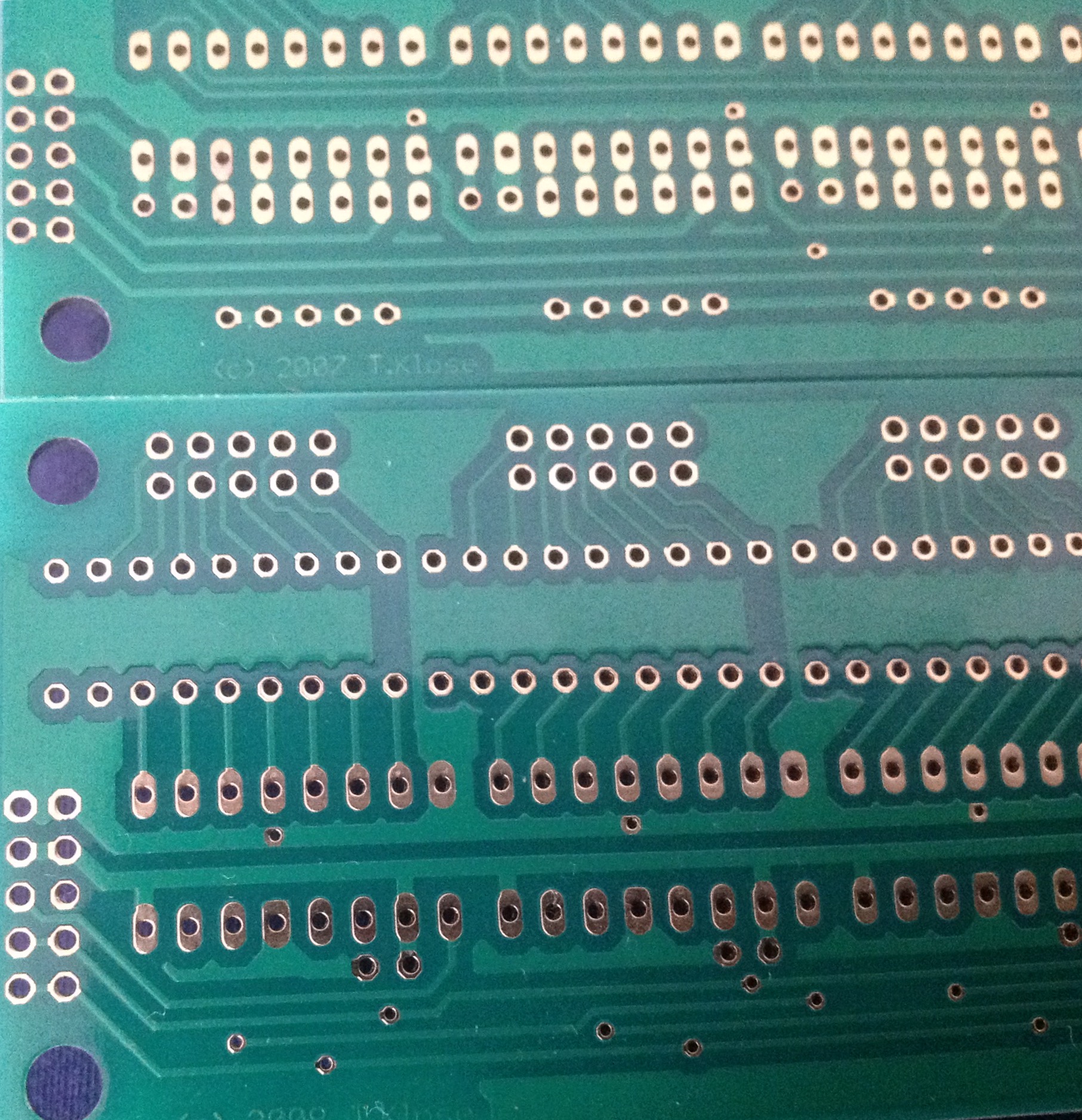
Mixed DIN/DOUT board -- clock and latch chaining?
latigid on replied to latigid on's topic in Testing/Troubleshooting
Okay, actually the r5 boards I've got both share RC (bottom pins on the 2*5 connector) but it makes sense to change the convention.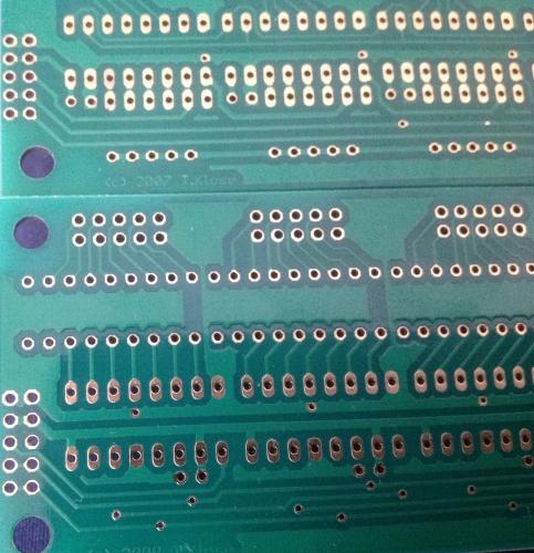
-
Damn, I had the same issue! The Quad IIC board should come with a warning! http://midibox.org/forums/topic/14581-4-x-iic-pcb-for-seq/?do=findComment&comment=171360