Search the Community
Showing results for 'STM32F4'.
-
I have an STM32F4 that refuses to work with both SD & ENC28J60 ethernet modules using MIDIbox NG & CV V2. Working: Ethernet and no SD When I boot it without an SD inserted, the ethernet works fine: Ethernet cable connected: yes Ethernet MAC address: 00:39:36:30:39:31 Ethernet services running: yes DHCP: enabled IP address: 192.168.0.100 Netmask: 255.255.255.0 Default Router (Gateway): 192.168.0.1 Not Working: SD and ethernet together (ethernet gets disabled) However, the moment I insert an SD card, I get various errors and the ethernet disconnects: [MIOS32_ENC28J60_PackageReceive] glitch detected - Ptr: ff09, Status: 7fb8 (max: 05ee) cd7f or [MIOS32_ENC28J60_PackageReceive] glitch detected - Ptr: ffff, Status: ffff (max: 05ee) ffff Working: SD and no ethernet If I boot with the SD card inserted, the MAC address is recognized but the plugged-in ethernet cable isn't detected (which could be due to another error): Ethernet cable connected: no Ethernet MAC address: 00:39:36:30:39:31 Ethernet services running: no DHCP: enabled IP address: not available yet Netmask: not available yet Default Router (Gateway): not available yet When this happens, my router actually recognizes the ENC28J60 and assigns it an IP address. Here's my cheap-o eBay ethernet adapter:
-
In the beginning of this year I decided I was going to finally build The Sequencer. I built my first MIDIbox project 4 years ago, a stereo MB SID, and have been hooked since. Next to my kids, this is the greatest thing in my life, I love it. There's so many great tutorials and tips on the forum about building the SEQ V4, so there's not really a need for another one, but I thought I'd share a few things I did in my build. I used the STM32F4 based Core, with the now available PCB. To save some space in the case, I moved and removed some parts. Removed the jack and the button caps. Cut the buttons and some pins. Moved some pins to the underside. I used the Kyocera LCD's, and read a tip by Altitude about the back light. I omitted the transistor and the resistors, put in a bridge and a multiturn trim pot. Like sometimes at Mouser, the part doesn't look like the picture, but it sort of fits ;) I wanted the max MIDI OUT's, so I used 2xMIDI I/O and 2xQuad IIC boards for 12 OUT and 4 IN The PICs on the second Quad IIC board needs a modified firmware. Tim AKA "Not Mike" AKA SmashTV has it now, but if you want to burn it yourself, it's downloadable further down. The rest of the build is pretty standard. Wilba PCB, Schaeffer front panel and common parts. The case is laser cut acrylic done locally. With the mods on the Core, it's only 4 cm. high :smile: While I was at it, I built the BLM 16x4 and TPD as well (FPD file further down) The last piece was the tinted windows on the TPD, and they really look great I think I am very happy with it, and it's so much fun to play. Thank you TK for everything. Thank you Wilba for the PCB ++ Thank you SmashTV for your shop and service ++ Thank you ilmenator for the BLM and TPD, and the "bling" and of course thanks to the rest of you for all the help, support and inspiration. Beers all around edit: I thought I could buy you all beers, but it's only TK that has a working link Wilbas redirects to a Rick Astley video :), and the others don't have one oh well Cheers Hal iic_hack.hex TPD+BLM_19.fpd
-
 Selling due to being too lazy to ever actually do any projects anymore... I have basically all the actual parts needed to build a MIDIbox Quad Genesis - barring all the generic parts like resistors/capacitors/ICs you'd need to add. That is: these boards and associated kits, including MIDI DIN sockets, included resistors, etc. - as originally bought from the MIDIbox Shop - so please see the links below for the full specs of what you'll be getting. 1 x Core STM32F4 kit + board = RRP $34 2 x MIDI I/O module kit + board = RRP $27 x 2 = $54 4 x MIDIbox Genesis Board (for YM2612) = RRP $5 x 4 = $20 1 x front panel PCB - this is a rare one, bought from Sauraen! = RRP $50 -- These are in brand new condition - I'd never even opened the parcels until recently... - and ready to go. Original prices are in the list above. That totals $158 USD, which is about £120 right now, but I'd definitely take £100 all in. I'm open to sensible offers. They need a home that'll use them, not just to lie in my next cupboard! Shipping will be from the UK. If you're in the UK, I'll ship for free. As for elsewhere, I've had a lot of experience of shipping cheaply worldwide lately, so it should be quite cheap, but message me first for a quote to confirm. -- Pictures of the items and original invoices showing the quoted RRPs are on imgur, since I get errors when trying to upload here: https://imgur.com/a/MNv5hE0 For more detail, I have uploaded front/rear pics of the front panel PCB, as well as front/rear photos of the 3 sets of kits: see them here: https://imgur.com/a/RY1RtLO The board in the photos captioned "OPN2 boards" are still shrink-wrapped, and I didn't disturb them by unwrapping. However, you can see they are more than just the OPN2 boards! We have 4 of the Genesis/OPN2 boards that were sold at the Shop (link), i.e. the green ones other, black PCBs: 2 shown on the top, which based on the IN/OUT connectors are definitely the MIDI PCBs another black PBC in between the above 2 sets, which must be that for the Core CPU kit. As for buying YM2612/YM3438/PSG chips, it looks like there are still plenty for sale on eBay, and probably elsewhere too. I might have some in storage that I could sell, but need to check.
 -
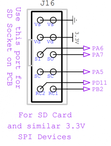
Dear Forum, I am trying to attach my SD Card using direct wiring, so no Core Board to host the STM32F4 Disc Board. For this I connected the SD Card Holder as written in red into the scheme, but Mios_Studio keeps on telling me, that no SD Card is found... Any help is appreciated, thanks! Emre
-
Hi I am in the research phase to build one of these beauties. I want to add an Ethernet port for the BLM emulator. Since the LPCXPRESSO is unavailable I believe I have to go with the MBHP_CORE_STM32F4. Has anybody used the MBHP_ETH sucessfully with this core? Is there a pcb/gerber for the MBHP_ETH available to buy? Cheers 6040
-
-edit- all parts are now sold! I have some kits for building Midibox Seq v4, all unbuilt/unused. SEQ CS pcb (smashtv) SEQ CS parts kit (smashtv) AOUT_NG kit (smashtv) STM32f4 core kit 2x MIDI IO kit I think I paid around £220 inc import taxes for the smashtv parts, the other bits were around £80. Asking £200 or make an offer. Located in UK, will ship WW.. happy to split shipping costs. Will add photos asap.
-
Hi i want to extend my project with 16 GLCD's. i found several threads about it but i'm still unsure how to connect the additional CS lines. the first 8 GLCD's work perfect connected to J15A... now i need to know how to connect the other 8 lines. found this wiki where it's stated how to connect additional lines from a J28 named connector. but on a "normal" STM32F4 the J28 isn't available... I read on an other thread that several lines are available on connector J10B. If I look at the schematic J10B is a normal GPIO against the J28 is a audio DAC. Can I use the GPIO's directly as they are to make 8 additional CS lines? if yes, do I need 220 ohm resistors on it? do I need an other boot loader configuration as the one described here in the MBNG manual? if no, how to use a SN74HC595N IC to generate additional lines? Where do i get the clocks (RCK and SCK, Pin 11/12 on 74HC595) and where comes the DISP SER IN (Pin 14 on 74HC595) from? thanks for some enlightenment, roberto
-
Hey everyone I'm trying to connect my MF_NG module to my STM32F4 Core via the MIOS IO. When connected via a different midi interface, the MF_NG module works perfectly fine. But I cannot get the connection via the MIDI IO module to work. Is there any special configuration in the NGC file I need to consider? I tried to route the incoming midi signals to the core like this: EVENT_MF id=2 ports=11111111000000000000 MF n=1 enabled=1 midi_in_port=IN1 midi_out_port=OUT1 config_port=USB2 chn=1 ROUTER n=1 src_chn=All dst_port=OUT1 I'm guessing it's wrong. Has anybody the answer to this? I'm starting to loose my mind over here... All the best! Frederik
-
Hi Here, I would like to know if it is possible to flash the mios Bootloader and mios applications on other cards than STM32F4-DISCO, for exemple on this boards : https://github.com/mcauser/MCUDEV_DEVEBOX_F407VGT6 I would like to know how it would be difficult to make Mios studio working with newer stm32 board like Teensy 4.0 or Stm32H743 board like https://github.com/mcauser/MCUDEV_DEVEBOX_H7XX_M Thanks for all, Best
-
 see title.... a friend of mine has a iOS device (apple), there it shows only 1 USB-Midiport, while on his Win-PC with the same STM32F4-Board it shows 4 Ports! any idea to fix this on iOS?
 -
Hi! I am looking for Core STM32F4 kit + board. Maybe someone has one for sell? Regards, Michał
-
do you need it for lpc17 or STM32F4 board? (ask because the tread was started for the other way round...)
i cant download the Gitubfiles (dont see a download button, and i am a offline coder...)... so i can take the one i have on harddisc - it is from 23.OCT 2018 (dont know if they are the same)--- or you show me how to download it...
-so lpc or stm32F4?
-
 Hi here, I try to modify the pin definition mapping between MIOS and hardware because I use a STM32F4VGT alternative board with a sd card directly implemented and the pins are differents for the midibox standard pins. I need to swap this standart Midibox Ports to this new ones : Midi box | Alternatie board From : To : How can I do that ? Thanks a lot by advance !
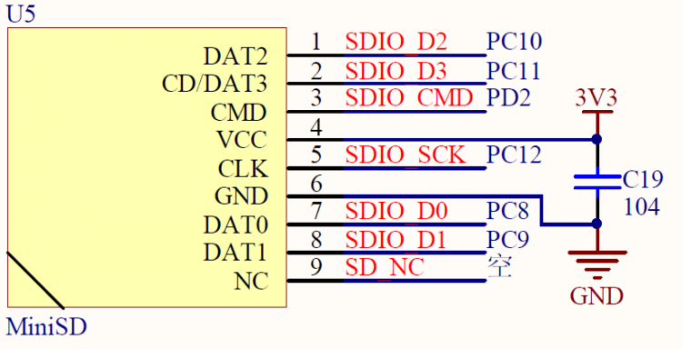
-
Hi, I im trying to run simple character lcd, without core module, but keep getting some random chars, or even just blocks, but it keeps blinking. I followed schematic from uCApps page for STM32F4, but the part to set Luminance i dropped and simply connected it to ground, Could be this a problem ? Tried to connect from scratch everything a few times, but still getting the same error... Please, if anyone has a tip what could be the problem, mine is that as i am lame at electronics, somewhere is connection problem maybe, im bit confused about the resistor array. Here is a video showing the behavior of LCD https://drive.google.com/open?id=1CPgCp6t-rewshbGq7Yprdonu_htadADo Thanks, Martin
-
This is MIDIbox FM V2.1, the STM32F4 version of the Gen 2 MBFM. Please note that this is not an official successor to MIDIbox FM V1.4, nor is it a project that is intended to be easily replicated by members of the community, at least not in the forseeable future. For the thread on MIDIbox FM V2.0, the same synth before I upgraded the processor from the LPC17, see here (some build information, more pictures, etc.): I have successfully upgraded my MIDIbox FM from the LPC17 core to the STM32F4 core, both hardware and software, and re-christened it MIDIbox FM V2.1. A stable, decently full-featured (but not 100% complete) build is available. I upgraded mainly due to RAM limitations on the LPC17 core, and now the LPC17 core will no longer be supported, in favor of STM32F4. Working features: MIDIbox NG V1 integration; all synth controls are MBNG parameters, so you can lay out and wire your front panel how you want. Menus are fixed, though, and certain controls (e.g. 18 voice-selection buttons with two-color LEDs, 8 softkeys, 4 mode buttons) are basically mandatory. Other things (e.g. controls for operator parameters) may be done how you like (e.g. MBNG banking). Supports 1 or 2 OPL3s (potentially 4, now that we have more RAM, though performance may become an issue). With 2 OPL3s (as I have), there are no noticeable performance problems, even when playing 30+-voice MIDI files into the synth. Edit all 18 (per OPL3) 2-operator voices independently; set up six pairs (per OPL3) of 2-operator voices independently to be 4-operator voices; set up one set of 3 (per OPL3) 2-operator voices to become a 5-voice percussion system. All OPL3 parameters editable and modulatable (even bit flags and separate audio outputs for two halves of a 4-operator voice). Set voices as polyphonic copies (DUPL) that follow parameters, or LINK them so they play together but have semi-independent parameters. Customize transpose, tuning, portamento, EG retrigger, and delay per voice. Arbitrarily assign two LFOs, one ADLDSR EG, velocity, mod wheel, and CC2 values to modulate voice, operator, or modulator parameters, per voice, up to 16 modulation connections per 2-op voice. Set up a custom temperament system (e.g. just intonation) with independent root note selection and frequency controls. One-touch switch to equal temperament and back. Intelligently assign voices to MIDI channels, the synth does the DUPL work (unless you disable it for custom configurations). Save and load named patch files from SD card in intelligent folder hierarchy and human-readable (editable, hackable) format. About 75% of General MIDI Bank 0 patches are complete. Customize synth's response to incoming MIDI messages: Bank MSB/LSB, Program, Pan, Volume, Expression. Enable/disable automatic patch loading on Program receive. MIDI mixer window with real-time-updating separate Volume and Expression controls per channel. Control MIDI input behavior per port. Not done yet: MIDI output port menu and behavior. The rest of the GM patch bank. There are some bugs with saving/loading 4-op voices, plus some untested (probably broken) corner cases for saving/loading complex LINK-DUPL voice arrays. The "wavetable" modulator (step sequence of pre-programmed values). The drum sequencer. AOUT support (beyond what is offered in MBNG). If anyone would like to build one of these, please let me know! I can send you information personally, or if applicable make a wiki page and/or put up the code somewhere.
-
Just want to share, that the new Behringer RD-8 drummachine is using a STM32F405. Maybe MIOS is an option as an alternative Firmware for those of you who own one.
-
Hi all, After having previously built an MB-6582, I thought I'd have a go at building a midibox FM. Following TK's build guide on ucapps, I've built the OPL3, DIN, DOUT, and CORE modules using PCBs ordered from Modular Addict. For the core, I thought it would be fine to use the newer STM32F4 module because it is mentioned as a more modern alternative to the PIC-based one. However, only after finding out more about it (my mistake), I'm now unsure if that was the right choice. I don't want to try to replicate Sauraen's 2.1 version because it looks far too ambitious for me and I need to rely on something fairly well documented and straightforward. My coding skills are very basic, and I just want to use the control surface of TK's 1.4 version. Is it possible to build the 1.4 version using the STM32F4 without writing or changing a lot of code myself? Or would I be better off using an LPC17 or a PIC-based core instead? I already have some spare PIC18F4685s, but I suppose if I use an LPC17 then I won't have to add a midi IO module later. Is that correct? I appreciate any advice. :-) Cheers, Theo
-
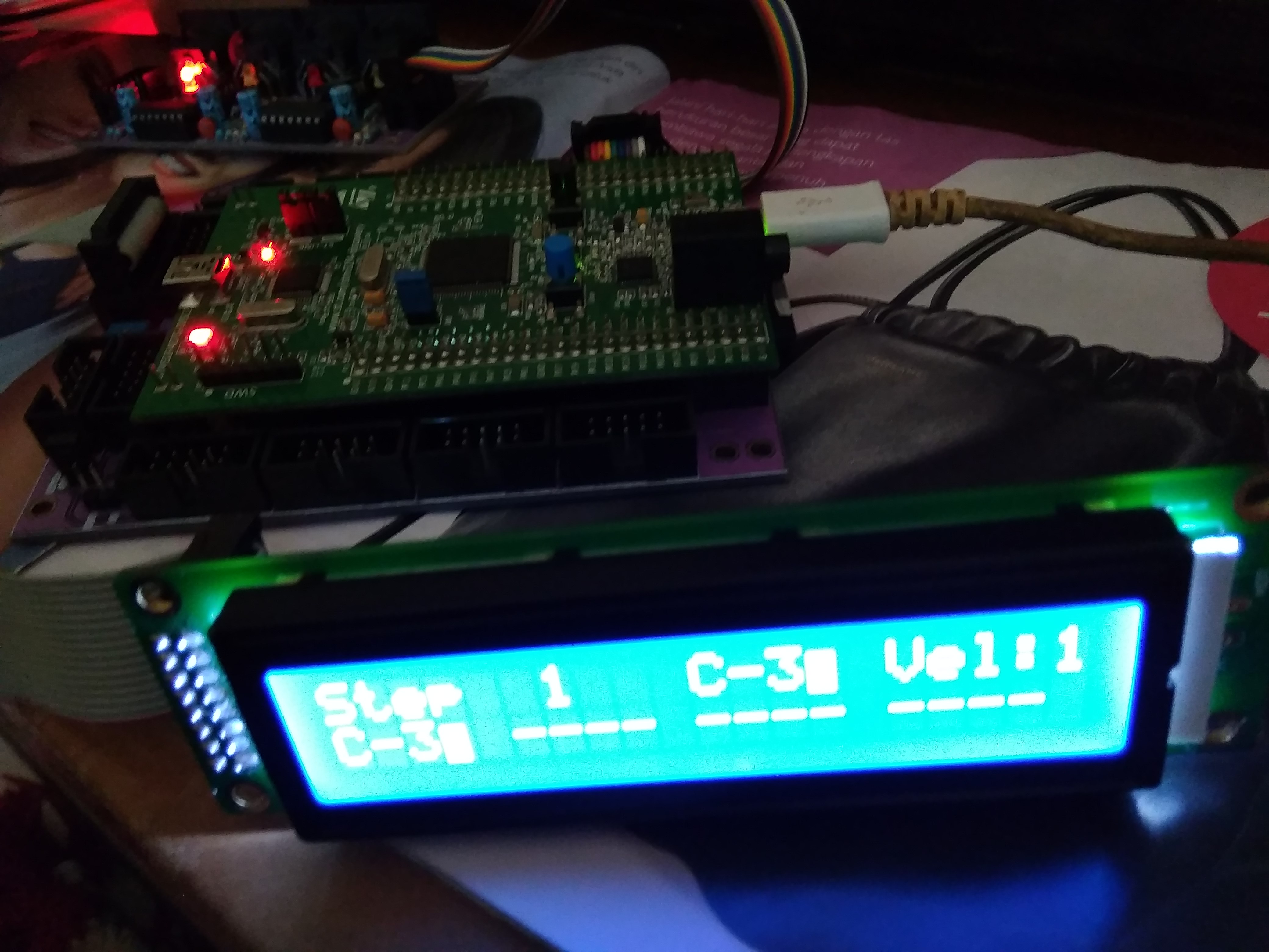
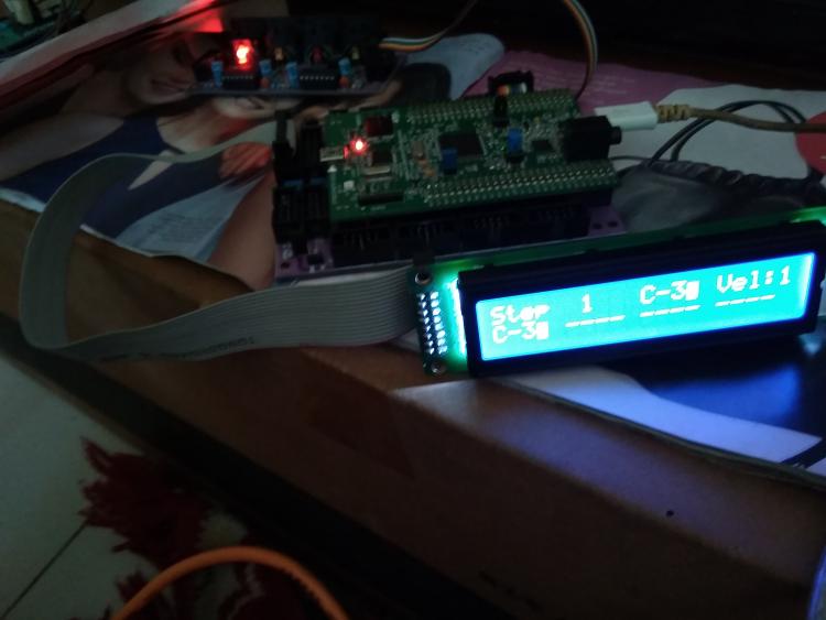
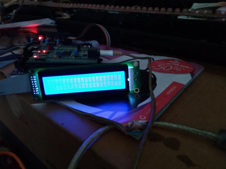
i have built the stibl stc32f4disc midibox correctly and after upload mios studio hex program also seq v4 already appear on my lcd 2x20 with brand not hd447780 (hitachi) but i try to insert mb ng through mios not show in my lcd i please give in suggestion , whether the lcd does not match the driver in mb ng or there is a system that must be in input as shown in my picture

-
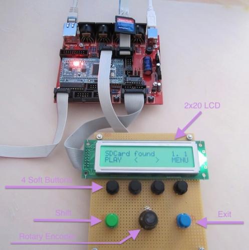
Hi all, I received my STM32F4 board in anticipation of building my SeqV4. I flashed the bootloader with ST-LINK on Win7 x64, and then used MIOS Studio to upload the SeqV4 application. From there, MIOS Studio doesn't want to talk to my STM32F4 anymore -- it sees 4 Midi ins and 4 Midi outs from the Seq, but no combination of those four ports will let me talk to it -- it says 'no response from device' or something similar. The bootloader fail-safe mode works (holding the USER button down on reset keeps it in the bootloader). But I can't communicate to it while it's actually running the Seq app. I think this is because of the known Win7x64 USB MIDI driver issues. But I find " The GM5 driver is currently not supported for the MBHP_CORE_STM32F4 module, but it's planned to provide it in future!" on the MIOS32 download page... so this driver won't help in this situation? I'd like to keep the four USB Midi In/Outs because I'll be using this thing with Linux mostly, but I can't get MIOS_Studio working on my Arch Linux install at the moment. The pre-compiled version didn't work, and compiling it from source caused me some GTK errors that I haven't sussed out. I'd also like to be able to update the Seq App in the future without having to disassemble my device to get to the button... Any help? I'll probably continue debugging the MIOS_Studio app on Linux to avoid Windows as much as possible, but I thought I'd ask here if there were any suggestions.
-
Hello all! I've run into a problem while implementing a granular synth on a STM32F4 Discovery using MIOS32. The synth algorithm makes use of floating point operations - I thought it would not be a source of performance issue, since the MCU has a dedicated unit for floating point calculations. Actually, there are performance issues, because the FPU is not enabled for the compiler (I'm using the original toolchain). There's a line commented out in trunk/include/makefile/common.mk: ifeq ($(FAMILY),STM32F4xx) # leads to a crash - reason not analysed yet #CFLAGS += -mcpu=cortex-m4 -mfpu=fpv4-sp-d16 -mthumb -mfloat-abi=hard -mlittle-endian -ffunction-sections -fdata-sections -fomit-frame-pointer # works (but FPU not enabled) CFLAGS += -mcpu=cortex-m4 -mlittle-endian -ffunction-sections -fdata-sections -fomit-frame-pointer endif I tried to uncomment that line, it compiled, but crashed for real on the MCU. Do you know if there's a workaround for that? What can be the source of this problem? Rewriting the synth algorithm is not an option, this is my thesis project, and the deadline is close. Thanks in advance!
-
Found some, thx!
-
Hello where do we connect the CS1 and CS2 of a GLCD 128x64 to the STM32F4 core. This is the way I think should be connected: GLCD STM32F4 1(CS1) ? 2(CS2) ? 3(VSS) VS(J15A) + 10K Pot 4(Vdd) VD(J15A) 5(Vo) 10K Pot 6(D/I) ? R/S(J15A) 7(R/W) RW(J15A) 8(E) E(J15A) 9(DB0) D0(J15A) 10(DB1) D1(J15A) 11(DB2) D2(J15A) 12(DB3) D3(J15A) 13(DB4) D4(J15A) 14(DB5) D5(J15A) 15(DB6) D6(J15A) 16(DB7) D7(J15A) 17(RST) ? 18(VEE) 10K Pot 19(A) B+(J15A) 20(K) B-(J15A) Attached the specifications of the GLCD I searched for this all over the site but I didn’t find anything about it. Have I missed something? Thank you WDG0151.pdf
-
Hi all For info I just check STM32F4disco at one of my regular component supplier, and there is a new one coming soon. So I check at manufacturer and the board is now NRND, replaced by something looking absolutely the same but with STM32F407VG in place of STM32F407VE. http://www.st.com/web/catalog/tools/FM116/SC959/SS1532/PF252419 I have no knowledge for understanding/comparison about change. Just to let you know there is certainly a need to check what's going on, and be sure MIOS/MBHP will run fine with new STM32F4 board Best Zam
-
 Christmas time is time to get some serious projects started! Hi, my name is Roberto this is one of my bigger DiY project and my first post here. first of all, this is a very cool platform, well documented and really expandable. what i was looking for! I bought a MBHP CORE STM32F4 and some modules like DIO, DOUT, AINSER64, MIDI IO and AOUT_NG. My goal is to build a midi controller to interact with an attached computer and software via usb midi. later i want to extend it to work with midi and control voltage outputs for synths/modular application. I have basic knowledge in electronics, decent soldering and some beginner programming skills. so more or less I’m a NOOB. I soldered all the boards except MIDI IO and AOUT_NG and made some tests and detected that i have PROBLEMS WITH THE INPUTS. Although i am able to send midi notes to the DOUT and light LED’s, I’m not able to get any inputs from the DIN (with buttons) nor AINSER64 (with faders). So, i’m stuck here right now and have some questions about it: The SD-Card Holder (and the SD Card) is missing on the MBHP Core, because i still wait for it to be delivered. Is it crucial to have it soldered? And, i didn’t planed to attach a LCD. Is it needed to make the whole thing work? here is what i did until now: checked for shorts checket IC, caps and cable polarity installed bootloader and firmware: https://www.dropbox.com/s/mg1oudmpp6ekajq/bootloader_firmware.png?dl=0 installed MIOS : https://www.dropbox.com/s/fo84lnr3t7h8610/mios.png?dl=0 installed MIDIO 128 V3 : https://www.dropbox.com/s/yhp1phjezwotdgx/midiio128.png?dl=0 checked DOUT with a RGB LED: https://www.dropbox.com/s/5txs634ny5yjple/RGBLED.mov?dl=0 checked DIN : https://www.dropbox.com/s/3p5clopkz8eivwl/DIN.jpg?dl=0 The button is attached to J3 (VS - D0) of a DIN module. I can’t see any incoming messages in MIOS Studio… Can i measure the functionality with a multimeter? All i see is a drop from 4.8v to 0v at pin 11 of IC1. But i guess it’s not possible to use a multimeter to measure the serial output… The same with AINSER64, Pot attached to VS - VD on the sides and A0 on the middle, no messages on the MIOS Studio terminal… The green LINK LED stays lit on the AINSER64, so i guess some communication is missed somewhere. I searched for solutions all over the site and i didn’t find any satisfying answer. did i miss something? all the best and cherry friskmas roberto
 -
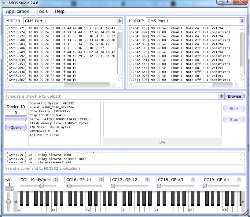
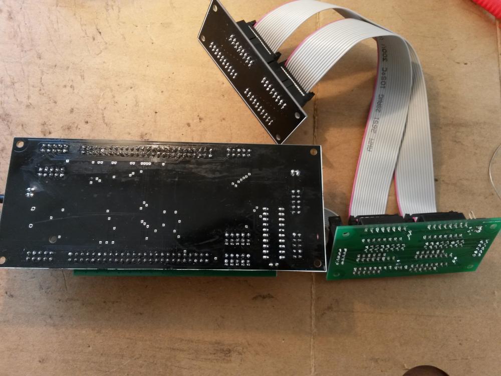
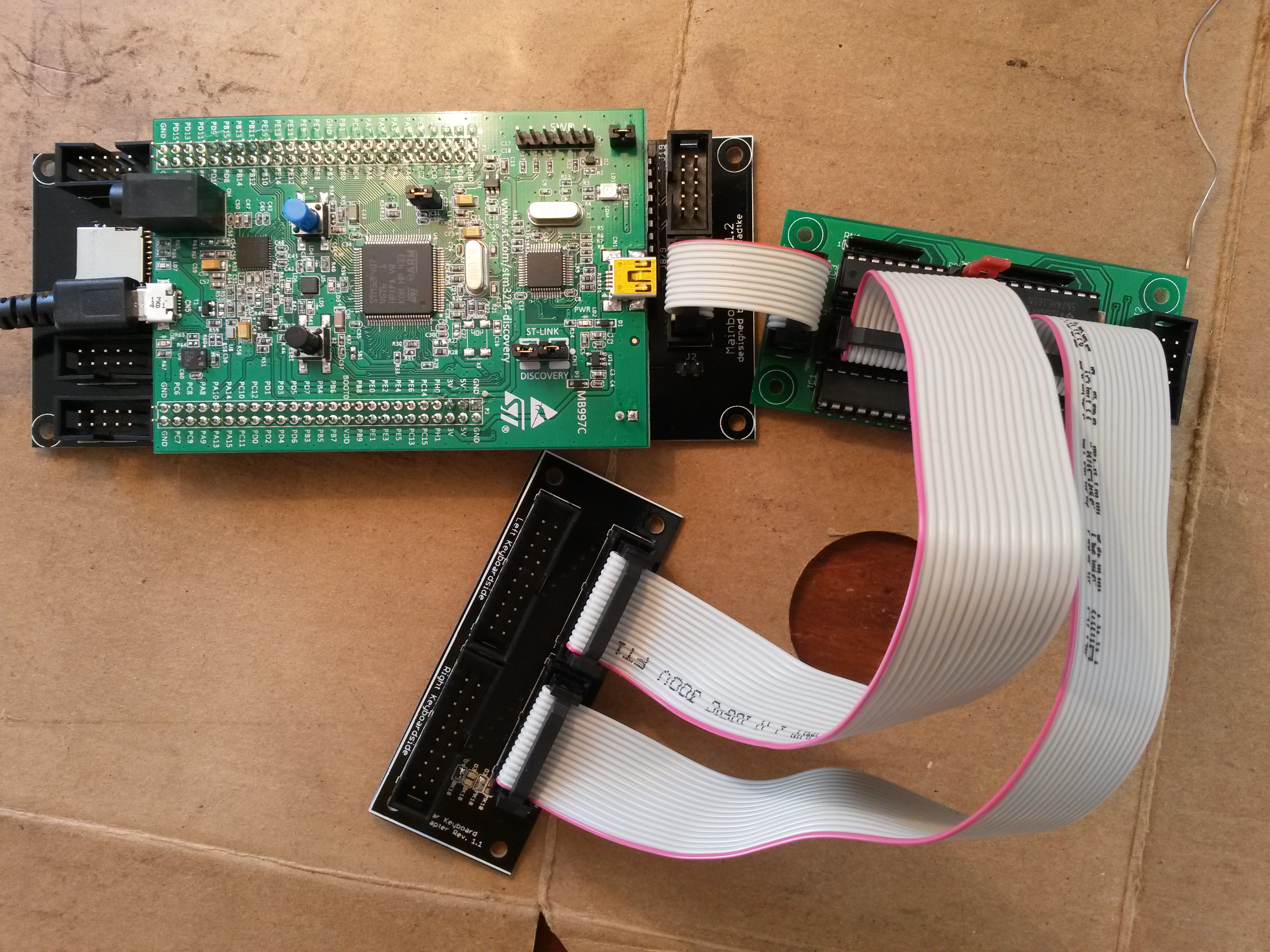
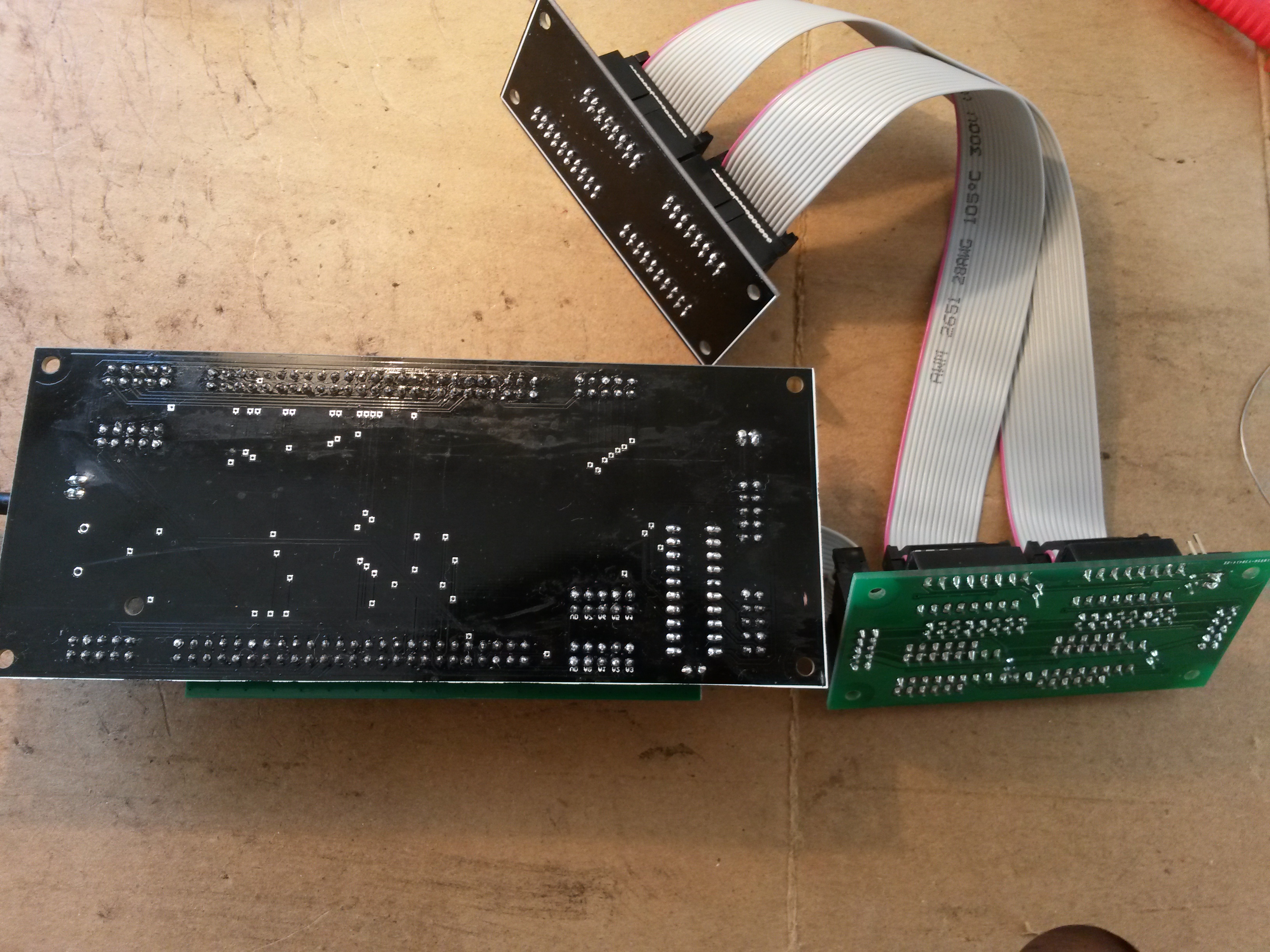
 Hello all, I've build my core stm32F4(fantomxr pcb) + diomatrix + fatar adapter to connect my 88 keyboard. I installed midibox kb and connected everything, but i can't output any midi, so i guess i did something wrong :) I tried the virtual keyboard and i didn't receive any midi input in my daw, so i was wondering if my setup was correct, it seems midibox kb is loaded correctly(cf picture). Here's the setup of my midibox kb: [13020.190] kb 1 debug on [13020.190] kb 1 midi_ports 0x0001 [13020.190] kb 1 midi_chn 1 [13020.190] kb 1 note_offset 21 [13020.190] kb 1 rows 12 [13020.191] kb 1 velocity on [13020.191] kb 1 release_velocity off [13020.191] kb 1 optimized on [13020.191] kb 1 dout_sr1 1 [13020.191] kb 1 dout_sr2 2 [13020.192] kb 1 din_sr1 1 [13020.192] kb 1 din_sr2 2 [13020.192] kb 1 din_key_offset 40 [13020.192] kb 1 din_inverted off [13020.193] kb 1 break_inverted off [13020.193] kb 1 make_debounced off [13020.193] kb 1 break_is_make off [13020.193] kb 1 delay_fastest 50 [13020.194] kb 1 delay_fastest_black_keys 0 [13020.194] kb 1 delay_fastest_release 150 [13020.195] kb 1 delay_fastest_release_black_keys 0 [13020.195] kb 1 delay_slowest 1000 [13020.195] kb 1 delay_slowest_release 1000 [13020.196] kb 1 ain_pitchwheel off [13020.196] kb 1 ctrl_pitchwheel 128 (PitchBend) [13020.196] kb 1 ain_pitchwheel_inverted off [13020.196] kb 1 ain_modwheel off [13020.198] kb 1 ctrl_modwheel 1 (CC) [13020.198] kb 1 ain_modwheel_inverted off [13020.198] kb 1 ain_expression off [13020.198] kb 1 ctrl_expression 11 (CC) [13020.199] kb 1 ain_expression_inverted off [13020.199] kb 1 ain_sustain off [13020.199] kb 1 ctrl_sustain 64 (CC) [13020.205] kb 1 ain_sustain_inverted off [13020.205] kb 1 ain_sustain_switch off [13020.205] kb 1 ain_bandwidth_ms 0 [13020.205] AIN Calibration Mode disabled. Then i wanted to check if my diomatrix was ok so i connected I1 to O1 on J3 to check for midi input, but i did not receive anything(no data in mios input). Is there a way to troubleshoot easily diomatrix ? or some tension to check on the core stm32F4 , i've checked my soldering and connection with a multimeter and everything seems ok. Thanks!