Altitude
-
Posts
1,184 -
Joined
-
Last visited
-
Days Won
30
Content Type
Profiles
Forums
Blogs
Gallery
Everything posted by Altitude
-
Ok, board revised for the Kobiconn connector available at mouser and reichelt. These are different from the hirshmann and CUI parts. Please see first post
-
i found a pactec case that matches the PT10 pretty well actually:

-
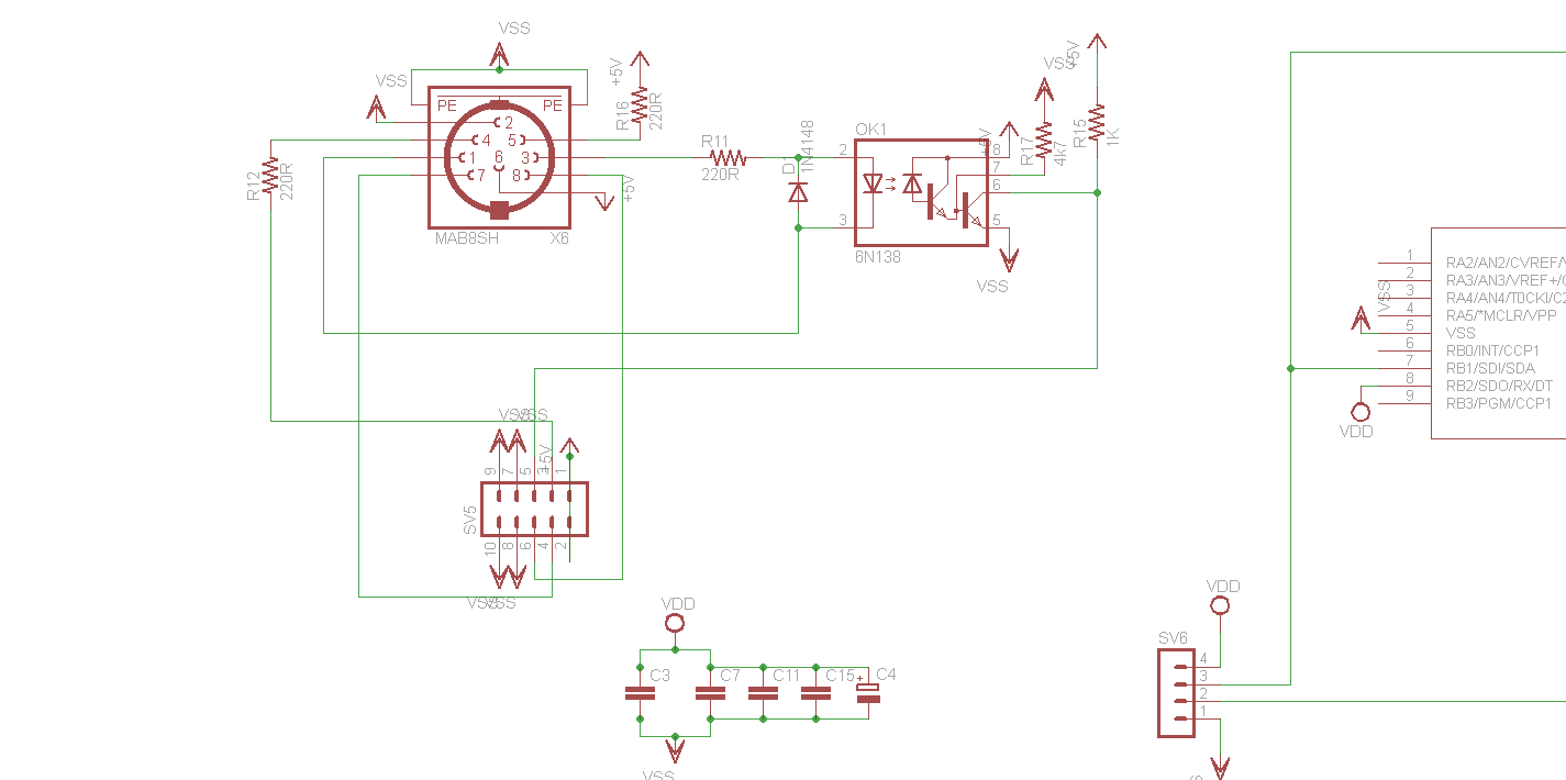
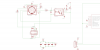
Ok, kinda hard to trace those pics so here is the schem I used for mine, maybe it will be easier to spot the problem there. As far as I can tell, pins 1 and 3 and 7 and 8 are swapped in your PCB layout but are shown the other way around in the schematic you posted. Can you confirm? Also, regarding the footprint, either should work. I ran into that type connector with my last GM5, it is different since it does not have the click-in tabs but will fit the same footprint. I'll make sure to leave more room though since the extra plastic around the pins needs more clearance This the DIN8 available here btw: http://products.cui.com/getPDF.aspx?filename=SDS-80J.pdf, the pins are numbered differently than the Hisrchmann part in eagle but everything else matches
-
Those are from mouser (http://www.mouser.com/catalog/catalogUSD/642/1903.pdf), but should be available from any electronics supply
-
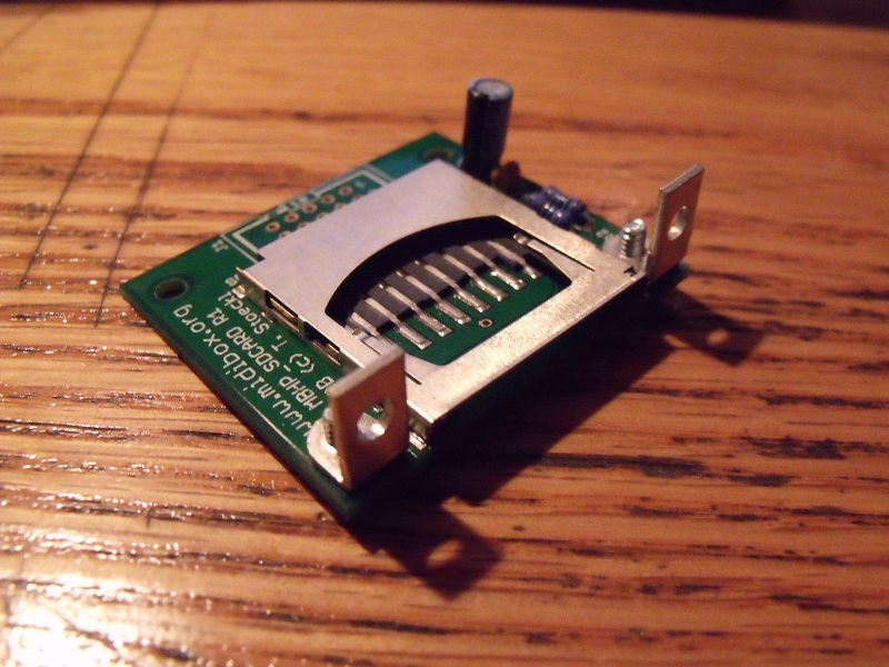
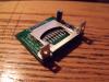
I actually decided to use some 90 deg brackets on the SD card instead of mounting it the bottom panel. This allows me to also mount the card sideways if I choose to..
-
How is the core set up? You should not have any problem running it directly from the +5 (bypassing the Vreg on the core) or the +15 (Vreg will get hot). If it is crashing, I doubt it is related to that.
-

Must buy a mixer for play my machines, need suggestions.
Altitude replied to ganchan's topic in Miscellaneous
+1 for for a digital mixer. I use an Old TM-D1000 16 channel and the flexibility of it compare to an analog one is amazing. I can set up my routing, eq, dynamics, save it as a patch, unplug it from the computer and I am off to the show! You can get the fabulous DM-24 for under a grand used. -
someone should just lay a ponoko one out, those would be dirt cheap and they have 2mm clear material. Personally, I just get some lexan film from mcmaster and sandwich between the panel and the LCD. They have thickness down to 0.005" , it's tough stuff, and cheap. And if you are REALLY concerned about your display, it comes in .44 magnum rated bulletproof as well :thumbsup:
-
Welcome aboard! (I dont think there are any gurrrls here, maybe smithy :turned: ) There are 3 different chips that are consider "SID" chips and the midibox SID is compatible with all of them: 6581: Original chip in C64. Bunch of revisions of this, bit noisey, "flawed", 12V powered (the MBsid has be built accordingly, it has options for both) 8580: Later, revised SID used in C64C and 128 machines. Improvement to chip, now 9VDC powered 6582: What the 8580 evolved into (identical), used in add-on sound devices They all have similar sounds and features, the controls will be the same for all. Right now, you have 3 options as far as building one goes: 1) Contact Wilba and get on the sammichSID wait list (complete kit) 2) Purchase MB6582 boards and partial kit from SmashTV. He offers a mainboard PCB and parts kit and the control surface PCB, you will need to source display, SID, and CS parts and buy a case and panels, everything is well documented in the WIKI, this can take 1-8 SID chips 3) Purchase a Core8 and mbSID pcb from smash as roll your own. Most advanced option, but has the most flexibility. You can get this running with just a LCD a few buttons and an encoder but a pretty steep learning curve if you are not into this kind of stuff.
-
Just stumbled across this. There is a free program called Dia (http://live.gnome.org/Dia/) that can easily convert SVG files into HPGL files compatible with front panel express. So: lay everything out in FPE -> print the panel as a PDF (i.e. cutePDF) -> open in Inkscape -> delete everything that you dont want to be a HPGL object -> save as SVG -> open in dia -> save as HPGL -> import back into FPE (some scaling will be required, haven't found the right scale number yet) -> save money ***big addition (this is from a recent thread on SDIY) There is a free program called uniconvertor that will also convert SVG to PLT but intalls a plugin to inkscape to allow saving to PLT from inkscape as well! http://sk1project.org/modules.php?name=Products&product=uniconvertor&op=download
-
I've been following that for a while and I have to say, with the new software, that is the most programmable midi controller I have ever seen. You can literally program that thing to do anything midi related (i.e HUGE sysex controls with as many values as you want, no 0-127 limitations here)
-
That mouser part is fine, I add added the extra pads for both the 5 and 8 pin connectors so ppl can use ones with either the 5mm or 10mm spaced pins in front. Like that pre-terminated 8 pin DIN cable though, might actually not be a bad idea just to terminate the wires that directly to the BLM instead of using the big DIN connector and save some space..
-
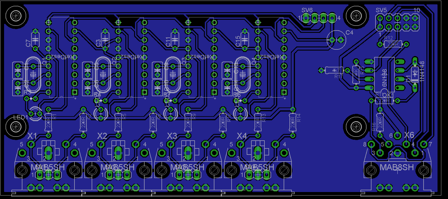
Done and done. The lower mounting holes have the same spacing relative to the connector side as the core32 for consistency(the lower right was off on the last rev), the top ones are different obviously since the board is not as deep. The second file is the 24 isolated version with jumpers for easier etching.. Also, the 8 pin DIN is available in the US at digikey: http://search.digikey.com/scripts/DkSearch/dksus.dll?Detail&name=CP-2380-ND
-
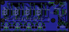
ok, double row in place, layout adjusted. I have the isolate on the small size (16) which may cause some problems for DIY etchers. I can do this no problem but I will release a revision with some jumpers and a 24 isolation as soon as this is done. My window is closing on access to the lab to make these so i want the basic layout done ASAP As far as pins go, I just go by the numbers. The deltron sockets I use are all numbered..
-
And the Rev 5 Schematic (which I cant attach for some reason) Rev 5 Schem
-
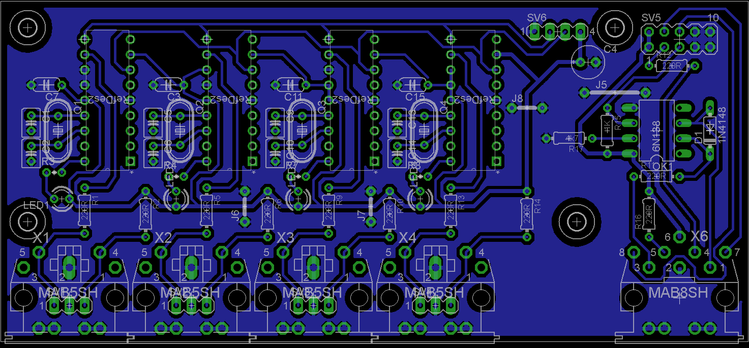
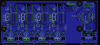
Done. I routed the pins for convenience with pin one and two being the midi in and out. I suppose one of those 8 pins should be gnd also.. V5 Changes: LEDs added MAB08 was MAB07 Added Midi IN and Out
-
 :whistle:
 -
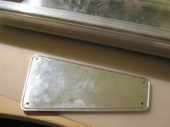
No, you cant add the lip to an already made panel, it is already the right height. It will fit just like TK's and can be attached with fasteners like shown in the pics. The panel with the lips needs to be made that way from the start. @ TK. Thanks for the pic of the slots. Do you think it is worth it to add the lip to the side of the front panel also?
-
Ok, that explains it. Adding the 1.8mm lips to the top and bottom of the Wilbapanel should be it then..
-
V2 of the front panel with lips matching the print.. FPD File DXF File
-
Ok, That drawing helps a bunch. So add 1.8mm tall, 1.5mm thick lip to the top and bottom of the front panel. One question however, the drawing shows 1.3mm lip on the sides of the rear, front, and bottom panels in addition to the 1.8mm lip on top. I dont see these in any of the pictures and I dont really know why they are there, can you confirm/clarify? Also, the front panel as Wilba designed it is 431.8mm wide, the print shows the width as 434.50 (which is 431.9 wide when you subtract the two lips, within tolerance), is there a slot on the end panels for those features to fit into? Is that print available in DXF? Id like to go over it in autoCAD if possible..
-
.. removed.
-
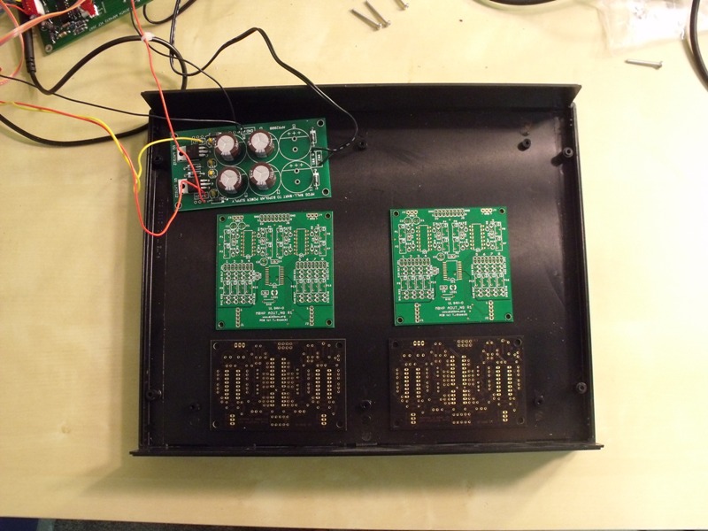
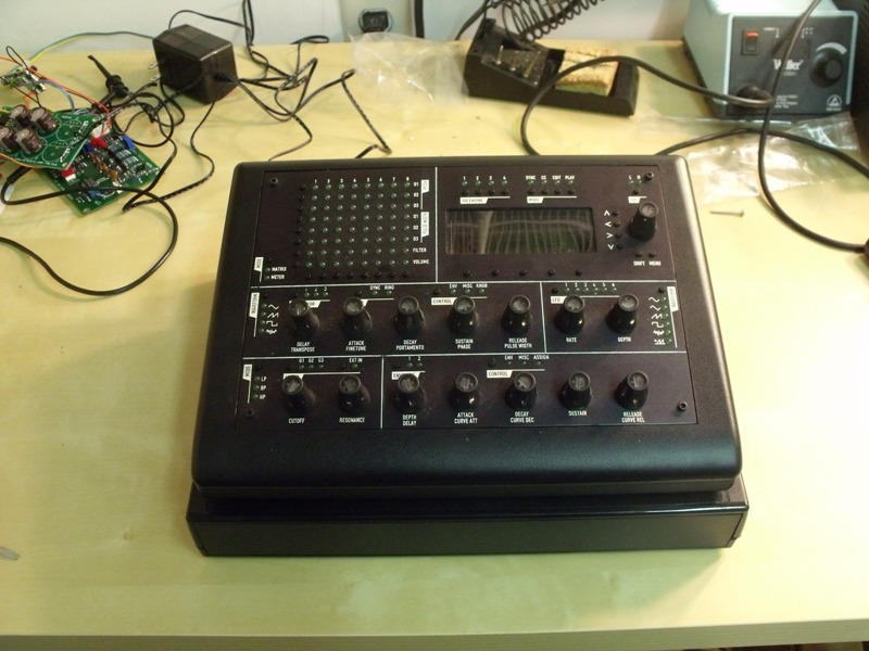
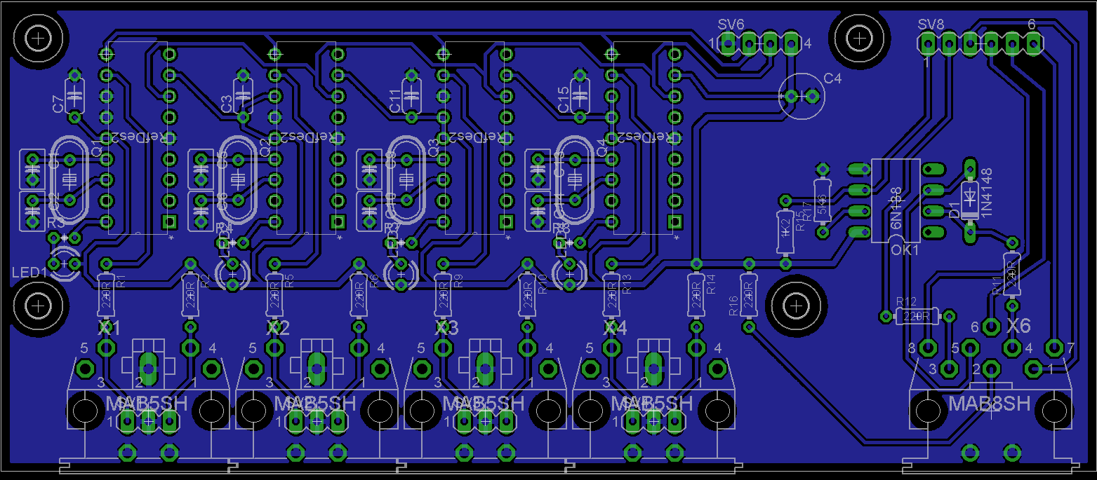
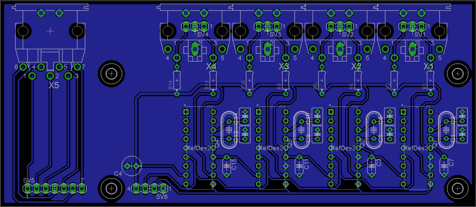
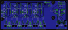
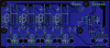
So now that I have some extra 1x1 GM5 modules, I decided to look at adding USB Midi to my JL Cooper CS-10 control surface for cubase. I bought this thing NIB for $25 but it was the old Mac RS-422 Serial interface (hence the price). The way RS-422 and midi worked on the old macs was a simple hardware conversion so it was simply midi over RS-422. The way i got this up and running was simply connecting an old Motu fastlane mac midi interface to the RS-422 port on the CS-10 and midi in and out to one of my GM5s. This worked fine but it was a tangle of cables (RS-422, 2 midi, and the wall wart) but i would like to par everything down to one USB cable. First thing I needed to look at was the current draw of the control surface. It is powered by a 9V Dc adapter which simply runs into a 7805 vReg. I bypassed the reg and ran it directly off a my bench PSU to see what it pulling and it draws a reasonable 130 mA. Next step was powering it off my 1x1 GM5, plugged in the fastlane and fired it up. Works like a charm! So this will work however I will need to scale down the fast lane to a simple one channel job. The conversion is simply done with a 1 mHz clock, and a 4049 hex inverter. I should not need the opto since everything will be running off the same supply (i'll need to verify this though, any input here would be appreciated) and instead of using a crystal, I'll use a resonator. The motu uses a 2 pin resonator with some load caps and for whatever reason 1 MHz crystals are $13. I have laid out a simple board to connect between the GM5 and CS10 and will be etching next week to see if it works!
-
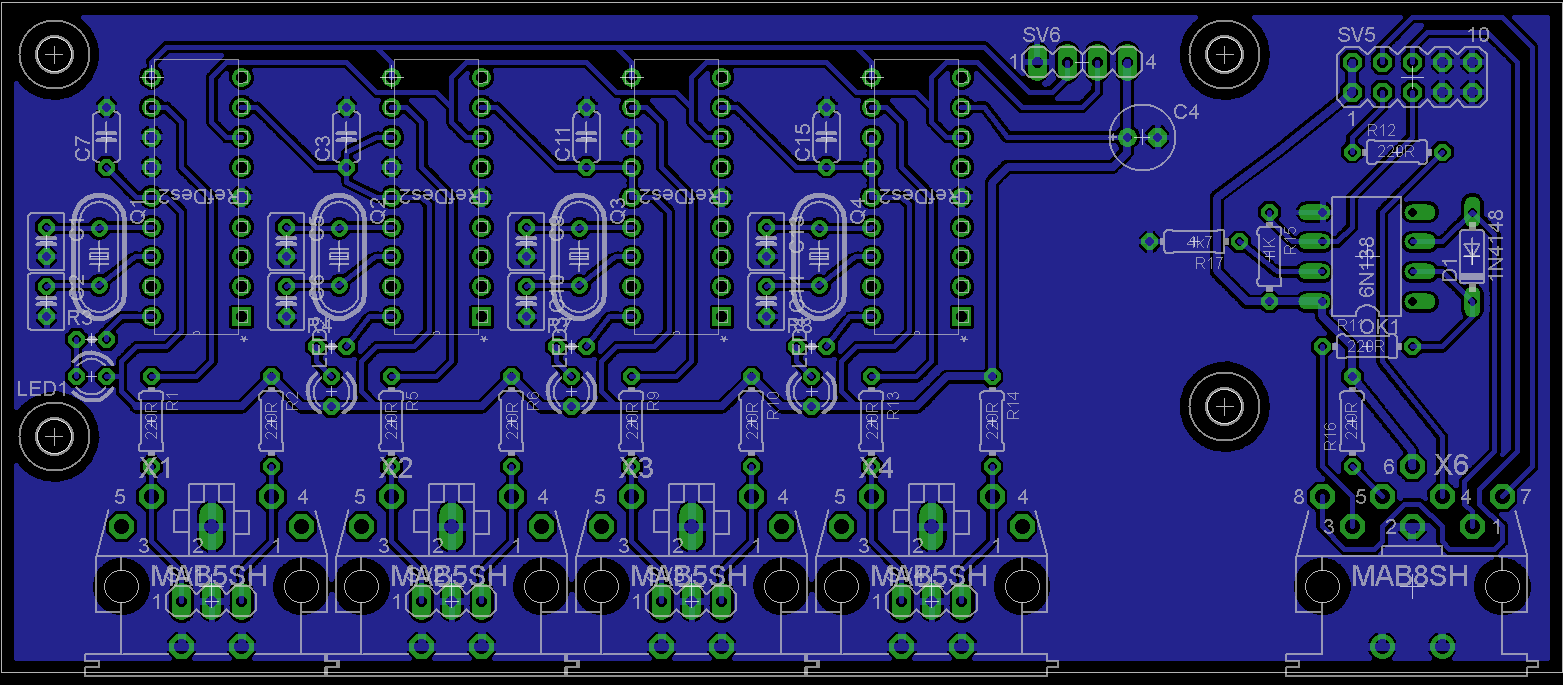
Damn, good eye. Your right, totally missed that. It should be connected to pin 7, not pin 6. Adding LEDs should not be a problem, i'll look at it tonight..
-
ok, Rev4