Imp
-
Posts
419 -
Joined
-
Last visited
-
Days Won
4
Content Type
Profiles
Forums
Blogs
Gallery
Everything posted by Imp
-
It's working again! Cheers to the one who fixed it!
-
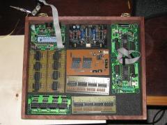
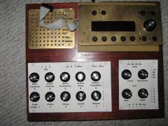
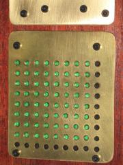
I used two layers of striped veroboard for the matrix, one for anodes, one for cathodes. Stripes where going left-right on one and up-down on the other. I can't recommend this approach though, as it's a royal PITA to troubleshoot.
-
You're not alone. It looks the same here. I tried with cleared cache, it didn't help. "Return to the index" leads to "404 - Wrong Page XX.XXX.XX.XXX" with X being my own IP.
-
SIDs are getting rare, but it will still be possible to buy single units for a long time, if needed. If your SIDs are working now, the chance of failure is quite low, anyway.
-
That might take away some of the brightness and the background may come out brownish. I'd try it anyway. It's a great idea. Did you check, if that particular Lcd is compatible with the MB6582?
-
Ah, ok. One less potential source of trouble.
-
I just tried to download the lemur template from http://svnmios.midibox.org/listing.php?repname=svn.mios32&path=%2Ftrunk%2Fapps%2Fprocessing%2Fmidibox_cv_v2%2F. It gave me an error: "Unable to open file: MIDIbox_CV_V2.jzml.r1982" As a quick workaround i copied the code as text and pasted it to a file. Lemur seems to be ok with that. But what went wrong? Do i need something else?
-
What i meant was: If a connection between top and bottom layer is needed, you usually use a via. If you do it like at the left leg of R16, you need to solder that leg on both sides of the pcb.
-
Did you solder the parts that connect to wires on top and bottom layer (e.g. left leg of R16) on both sides? btw. I'd rather not troubleshoot Aout and filterboard at the same time. Better test the Aout with a multimeter and the Filter with some kind of makeshift voltage source (pot as voltage divider). This way one won't fry the other.
-
I once repaired a Flatscreen with Caps i scavenged from a SIDless C64. Despite their age, they worked until then, so i figured they were good for another few years. The nice coloured ribbon cable of the keyboard can be reused for Diy or repair projects, too. It's a little sad, to pull such a great machine apart, but the ones i had were in bad shape anyway.
-
I don't know the CEM, but i got Seppoman's dual SSM Board in my SID. Unfortunately it cuts the bass, as you turn up the resonance. So I'd rather go the CEM route, next time. Or build something discrete, like a Polivoks clone.
-
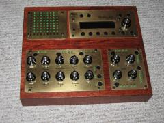
That's awesome! That color scheme looks kinda toxic.
-
What i had in mind was just a 3U Faceplate with square cutouts which fit the sammiches frontpanels. Nothing fancy. It could be the same material as the sammiches. If they were mounted so that the surfaces sit flush, it would nearly look like one piece. I doubt that plastic from Ponoko is sturdy enough, though. It could surely use some metal support structure beneath.
-
For 1U, you would need to redesign the CSs, which is more work than rerouting some jacks, i think. Also it might prove difficult to fit the buttons below the LCD. That said, i'd go with 3U. As a low-cost solution you could keep the front panels and merge them with a 3U-frame, instead of having a whole new panel cut.
-
I'd remove the CV from that chain. What you propose is converting digital to analog and then to digital again. Those VU LEDs could be driven by a LED matrix, which contains shift registers. That would be much cheaper and easier to build.
-
Sounds like there is some unintended cc-automation going on. Maybe your DAW caught some controller values while recording?
-
Ja, die erreichbaren 78hz sind wohl etwas zu tief. Für Drums und Bässe reichts vielleicht.
-
Mit Thorstens Vorschlag ließen sich mit sehr kurzen Delayzeiten auch saitenähnliche Töne erzeugen. Karplus-Strong-Synthese nennt man das. Dabei bestimmt die Delayzeit die Tonhöhe.
-
What i would try is using a separate 7805 + some caps for the fan. Although i remember someone mentioning that hose regulators have a bad ripple rejection, i think it should be better than a resistor.
-
I'll take it. With special german shipping option please.
-
Ich glaube du meinst eine Pfostenbuchse, oder? Aber in 4x8 hab ich sowas noch nie gesehen. Hier, ist es das?
-
Would it be feasible to have only the CS in a separate Box and the Core etc. in the modular cabinet? That would require a long connection between Core and DINs/DOUTs, does that work?
-
-
-
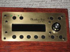
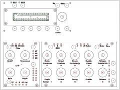
From the album: imp`s Zeug
-
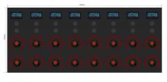
Since Sneakthief made it easy for lazy folks like me, i just modified the .psd a little. Some thoughts: -symmetry makes it southpaw-friendly -could easily be scaled to builders needs -only one type of display->lpc17 will suffice -could be used as 1 OLED, 2 buttons, 2 encoders per CV channel -could be built without LED-rings, OLEDs could show values