Search the Community
Showing results for 'STM32F4'.
-
Hi all, I want to build the STM32F4 module pcb, but I'm not sure what the parts list is for what goes on the PCB. Is there a parts list anywhere for what goes on this PCB? Is there a SmashTV kit available that has all of the parts that go on the PCB, or would I need to order those from another supplier? Thanks, John
-
Hey, I'm experiencing something odd - if I call EEPROM_Init(0) in APP_Init then I cannot upload code using the bootloader unless I reset the board and hold the user (blue) button. Has anyone else experienced this? I'm guessing this has to do with EEPROM_Init touching the flash and somehow messing it for the bootloader... Thanks :)
-
I came across this today https://github.com/MrBlueXav/Dekrispator I've loaded it on to a STM32F4 and it actually sounds rather good. Has anyone else tried this out? I can imagine a very cool cheap synth based on this code.
-
Hello, I got my STM32F4 board today, and for reasons beyond my understanding I cannot get any LEDs other than LED1 to light up. I am modifying the application template - so my code is as minimalistic as it gets. If I call MIOS32_BOARD_LED_Set(1,1), the green LED turns on. MIOS32_BOARD_LED_Set(2,1) or even MIOS32_BOARD_LED_Set(0xF, 1) do nothing. Some answers to potentially obvious questions: 1) I am certain I am properly recompiling the code and uploading, as I see the green led no longer lighting up when trying MIOS32_BOARD_LED_Set(2, 1) and lighting up again when I switch to MIOS32_BOARD_LED_Set(0xF, 1). 2) I tried commenting out the code in the timer function and simply turning the LEDs on in APP_Init() 3) I am compiling using the following env variables: export PATH=$PATH:/Users/eran/Projects/mutebox/gcc-arm-none-eabi-4_7-2013q3/bin export MIOS32_PATH=/Users/eran/Projects/mutebox/mios32-svn export MIOS32_BIN_PATH=$MIOS_PATH/bin export MIOS32_GCC_PREFIX=arm-none-eabi export MIOS32_FAMILY=STM32F4xx export MIOS32_PROCESSOR=STM32F407VG export MIOS32_BOARD=MBHP_CORE_STM32F4 export MIOS32_LCD=universal What am I missing? Thanks!
-
 Hi everyone, I have a strange problem with my STM32F4 Discovery not being able to communicate with MIOS studio. I flash the STM32F4 with the mios32 bootloader no issues via ST link, but then if I reboot the core and connect through the left Micro-USB, the USB MIDI driver doesn't come up on either windows or macOS (so I can't connect it to MIOS studio). If I boot the core in boot hold mode, the USB-MIDI driver comes up on both Mavericks or Win7 (MIOS bootloader) the core gets recognised and can upload an application (ID=0), but when I then upload midibox_seq_v4_086 and reboot, even though it works on the displays of my MbSeq4, no USB Midi drivers again in either Win7 or Mavericks. To test further, through boot hold mode I uploaded midio128_v3_019, reboot, and the drivers do come up and I can use the terminal, but I get 'No response from MIOS8 or MIOS32 core' (I've checked with all Device ID values, none works). If I now try to upload midibox_seq_v4_086 I get the 'Warning: no reponse from the core' message half way through and the core doesn't seem to send an upload request after booting. I have done this when the STM32f4 Discovery board is not connected with the MBHP_CORE_STM32F4 module and it exhibits the same behaviour. Is this midibox_seq_v4_086 messing up the USB midi drivers somehow? Or perhaps some residual code somewhere if it connects under boot hold? Any help is much appreciated!
 -
Hallo zusammen, ich stehe mal wieder auf dem Schlauch. Möchte gerne meinen DIY-Tube-Preamp midifizieren. In einem ersten Schritt soll für einen Prototypen der Volume-Poti verschwinden und eine Lautstärkeregelung über das PGA2311 erfolgen. Es hapert im Moment an der Verdrahtung von diesem IC mit dem STM32F4. Hat jemand einen Schaltplan hierfür?? Mwpost
-
So reading through the documentation, I find this statement: "..but as long as only OSC messages should be sent and received, the external MBHP_ETH module might be sufficient..." I'm thinking about laying out a combo ETH/USB module for the core and am a little concerned about the "might" part of that. Is this something that is not tested at all and should work in theory or not tested at all and who knows if it will work?
-
 I have used the software provided by ST to input the bootloader into the Discovery Unit when plugged into the PCB. I have a very small number of components on the PCB . (Namely IC1 and IC2 and their capacitors and the R33 resistor network) The problem I found was that the ST Link software would not recognise the bootloader hex file. I messed around a bit and the tried the exercise again this time using the Discovery unit on its own. The hex file was recognised and the bootloader apparently loaded. Is this normal? I am wondering whether there is a problem due to there being no power on the IC's. Maybe someone can explain. Regards Robin
 -
Gibt es irgendwo ein Layout zum Selberätzen/Lochraster? Danke; Grüße aus Kiel
-
Having given up on using Windows 7 with MIOS STUDIO I have switched to a PC running LINUX (Mint). MIOS STUDIO seems to work properly. I have managed to download hex files using MIOS STUDIO, it would seem. However I would like proceed slowly and looked for an application that I could use to check that the STM32F4 core is OK. Tutorial 5 seemed to be the ideal candidate as it only needs shorting links to be applied to J5 connector. I am not sure whether this APP is ready for STM32F4. I get no response Please let me know if this is the case and if not let me know if there is another application that would be suitable. Or, whether I am likely to have a fault on the hardware. Thanks Robin
-
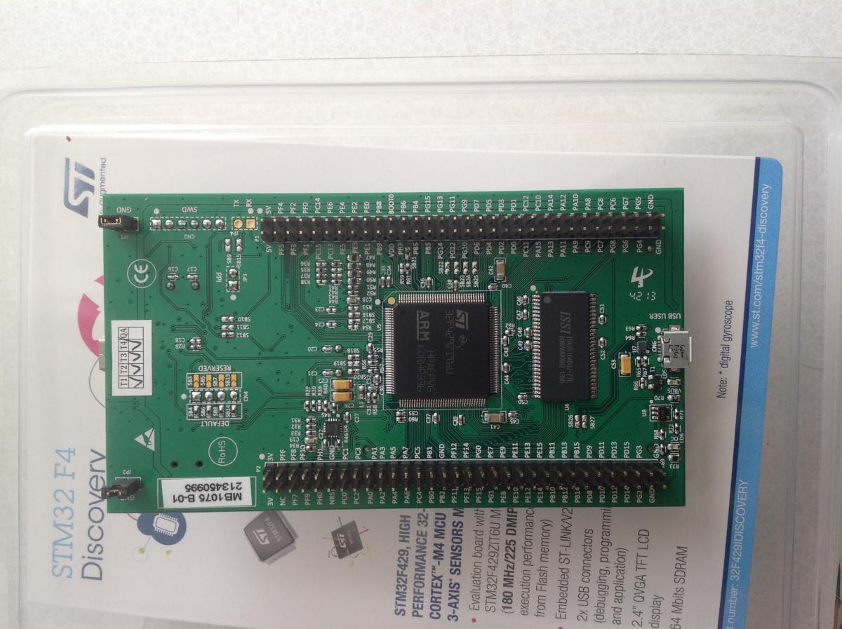
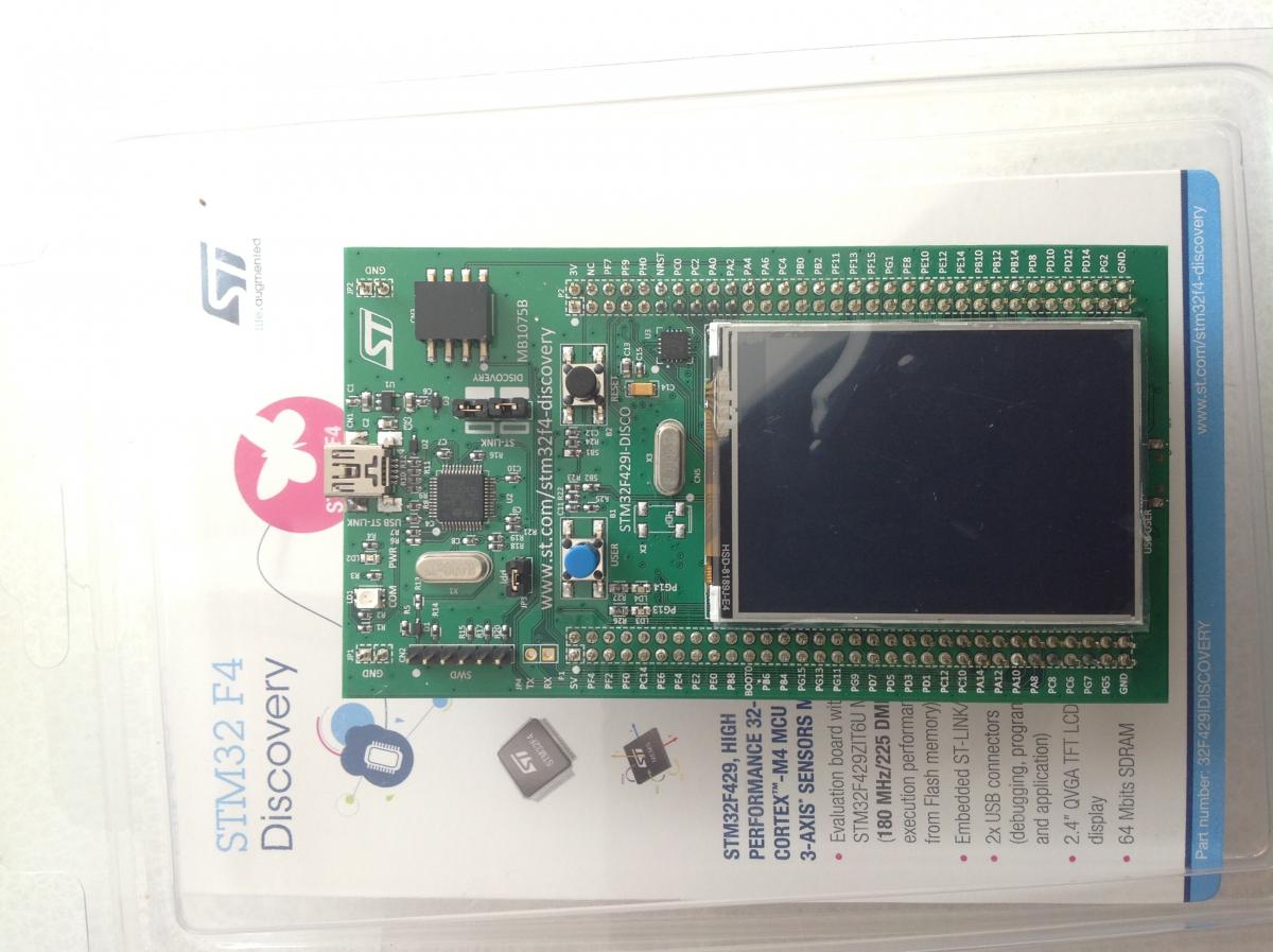
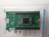
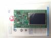
Hi all, i was a little bit surprised when my new STM32F4 board arrived because i ordered this one: Link But i received this Version Now the big question: Is it compatible? If needed it would be no problem to change the core board wiring. Best regards Marxon
-
Hi all, i would like to know more about OLED displays and how to connect and use them. It looks like you can connect say 8 OLEDs via J15A on CORE_STM32F4. I assume these wirings are ok for STM32F4. http://www.ucapps.de/mbhp/mbhp_lcd_ssd1306_single_mios32.pdf http://www.ucapps.de/mbhp/mbhp_lcd_ssd1306_multiple_mios32.pdf Every OLED gets it's own CS-Line (CS0-CS7 on J15A) and all other pins are connected in parallel. What does the X = 0..127 or X = 128..255 values mean? Edit: here it is better pictured, should work http://wiki.midibox.org/doku.php?id=oled
-
Hi all! While working on my Midibox NG, I was careless for a moment and powered the STM32F4 core with too high voltage. :cry: Now it seems that something is faulty on the STM Discovery board because there is a short circuit between the GND and 5V pins (4 ohms). My first thought was to check diode D1, D2 and D3, but they are OK. Now i guess U1 or U3 might be have been destroyed but before i start to desolder them, i first want to ask if somebody might better know what to check . Thanks a lot for your help! :thumbsup: Best regards Marxon
-
Hi! First, let me introduce myself. I'm Thomas, sound engineer, I'm working mostly in audio post but have a small home studio where i record small bands. It's been a long time since i started thinking about making a midibox NG, but other projects kept me busy (I built a few preamps for my home studio as well as other audio gears) But now, i finally have time and hopefully make it a reality. I will try to keep this thread updated with my progress and experiments. So first, i'll expose what i'm aiming for: My goal is to build myself a Midi controller that is basically a Mackie Control with a few more features to control Nuendo. I really want it to be as ergonomic as possible, and today, no controller on the market would fit my needs completely. (maybe Nuage systems, but that's a bit expensive) Midi-wise, i will use 3 ports as Mackie Control and one as a Generic midi. (feature that you can set as you wish in Nuendo) I want: -25 faders: 24 using MAckie Control and MC expanders + one using Generic Midi to control selected channel in DAW -Each fader will have 4 buttons, an encoder with led ring and an oled display on top (just as any MCU) -transport buttons -various array of buttons with MC features as well as window management, automation features, some edit functions... -a Jog wheel -a surround panner -one bank of encoders to control selected channel EQ -another bank of encoders to control Selected channel Dynamics -Control-room commands. I think that's it for wanted features. Now for things i will need: As i understand i'll need: -2 STM32F4 Core module (1 main and 1 for MF_NG modules) -4 MF_NG modules -a bunch of DIO matrices for buttons and LEDs. -and probably an AINSER8 module. I already own a STM32F4disco and i made my own version of the core module. I went through the tutorials, and i've been playing a bit with a beaboarded Din / Dout. Joined is a block diagram of the way i think My different modules will fit together. Hopefully i got this right... I still have alot to do / learn, but feeling really excited about it right now! And i'd like to thank Thorsten and everybody involved in the midibox project for all they have accomplished. This is great! Cheers, Thomas Block diagram.pdf
-
Hello guys, I am facing a stupid problem with a LCD (4x20) connected to the RTP-MIDI core... It simply does not start. I am sure that I forgot something somewhere, but I can't find what I have verified all lines under the bootloader using the testlcdpin command, everything is fine I have set the display size to 4 x 20 in the bootloader In my app, in the APP_Background, I have put this sequence : MIOS32_LCD_Init(0); MIOS32_LCD_Clear(); while (1) { MIOS32_LCD_CursorSet (0,0); MIOS32_LCD_PrintFormattedString ("TEST"); } but my display clearly does not even initialize (I see the "default" squares when I set the contrast to the max). Moreover, I was expecting activity on pins PA8, PD3 and PD6... but nothing at all (checked with my oscilloscope), like if the LCD driver did not start at all. What did I miss ?
-
Is it possible, as an alternative to STM32F4DISCOVERY board, to use the better STM32F429IDISCO, offered with an integrated LCD and more I / O? Regards Karl
-
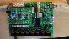
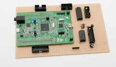
From the album: RTPMIDI_CORE_STM32
Picture of the first assembled RTP-MIDI CORE STM32F4 board, equipped with the RTP-MIDI OEM module, and doing the first test run.© BEB
-
I noticed that a port to the STM32F4 Discovery has shown up in the MIOS sources. What is the status of the port? Is a new Core board planned? The STM32F4 parts have a few features that the LPC1769 doesn't, mainly a proper SD card controller that can use 1 or 4 bit modes instead of SPI, should be a lot faster; and an external memory controller for SRAM or additional Flash. Unfortunately the 100 pin part on the Discovery board doesn't expose all the pins needed to properly interface with external memories, but for synth/sampler-types of instruments the prospects of a MIOS with access to megabytes of fast storage is quite exciting I think :smile: The Discovery board does have the nice feature of an integrated audio quality stereo DAC, which I'd hope to see supported.
-
Hi all, Thank you for all your advice and input... this was one of those times where doing the same thing multiple times yielded different results , and I still don't really know why, but I will explain the steps I took below just for anyone else's future reference...( Its worth noting that I had a couple of days when the forum was down, so I was kind of scrambling around outside of the steps recommended here ) I got to thinking maybe my USB drivers were causing the connection issues between my midibox and the MIOS Studio ...so I downloaded and attepmted to install the drivers (however I note that they say they are NOT related to the F4 board that I seem to have... and they didnt seem to like to install on my Windows 10 PC ( install ended in an error) BUT I do wonder if this action may have caused the native drivers to refresh somehow... as the next time that I plugged in I did it in this exact order 1. laptop on 2. hold down blue bootloader button on the board ( I had to physically continue to hold this blue button throughout ALL steps below...maybe get someone else to do this ) 3. insert USB form Midibox to laptop (get the ding dong noise on the laptop) 4. select MIOS32 Bootloader on MIDI in and MIDI out dropdowns within Mios Studio 5. This finally showed up the bootloaders details vrsion, board etc in theLEFT hand box below the input dropdown.. 6. clicked on browse and located the unzipped midibox_seq_v4_096. folder and found the stm32f4 sub folder inside it...and the project.hex file inside THAT 7. clicked start and let it upload ( this took a bit of time and to be honest I get it a bit longer at the end just cos I was worried about unplugging early 8. I then released the blue button, unplugged the usb to my midi box and closed mios studio 9. plugged the Midibox back into the USB 10. restarted Mios studio ( squeal with delight that the default hardware config file is now showing and I am finally passed the bootloader screen ) at this point I was back to the Midibox starting up but pressing my onmidi box save button was still coming up with the SD card Error... 11. I then typed 'help' into the terminal on MIOS STUDIO to get a list of command, I spotted that you can create a new session with the words new 'namehere' 12. I then created a brang new Session via the MIOS terminal ..this took quite an unexpected long while....all the time I had two progress bars on the screen of my midi box, it may have taken around five minutes to complete...I just let it run 13. I powered off the midibox once completed and changed to powering it via the wall plug rather than my laptop and lo my new session (named "apple") was now the active session upon startup and it SOULD be read to / saved to etc. after that it was just a matter of putting all the midi channels , ports, bookmarks etc back to how I like them and saving as I go ... and since then I have taken the unit out and performed last night and it was back to working perfectly ( except the screens turn off when bumped..but I am sure thats a physical issue with a cable somewhere that Ican fix) thank you all for all your support and help , I know I am thick as two short planks when it comes to diagnosis and repair , but you where all very helpful. Phill
-
I never said it shouldn’t be a hardware link. Maybe the right term is „debug Interface“, … …but I don’t have STM32F4 in use for my mbseq.
-
Hi Latigid and others, It's really been a long time since anyone mentioned something about MBCV V2, but I'm really curious if there was some progress in your alternative version. Your build looks really good but we never saw the finished project, like with all MBCV V2's........ Last month I powered on my own build and I was again really impressed by all possibilities. It took a while to connect it to my Ipad/lemur but I succeeded and I compiled new MBCV V2 project.h files from the mios32 github for LPC1769 and STM32F4. My own test version is on a LPC1769 but I want to make a new one on a STM32F4 core. But I can't get my ethernet module and SC card to work simultaneously. I red that Rowan and Sneakthief had the same problems , see here When I upload midibox NG to my core the ethernet card and Sd card do work simultaneously. You are also using a STM32F4 for your mbcv v2.01, did you get it to work with ethernet and SD card at the same time? Hope to get some answers after all these years....cheers, Roel
-
I can't find a jumper on the STM32F4 core board for the bootloader hold mode - what is the easiest way to get my core board back to life after it crashes with a hard fault during init? Thanks, ilmenator
-
-
Hi, just to let all the KiCAD users know there is a very nice library / footprint with accompanying 3D model for the STM32F4 discovery board (and lots of other good stuff) out there from Walter Lain. Go check his homepage! Best, ilmenator