Leaderboard


Popular Content
Showing content with the highest reputation since 07/28/2023 in all areas
-
Hey man. It's actually an FR4-Standard PCB. Non aluminium. But seems pretty robust anyway.2 points
-
More like 7 years later :D Update 2024 I wanted to use my MIDIbox SEQ V4 more, in different situations, and make it more portable. I have made a new case in aluminium, so I can move all the modules, the CS frontpanel and the MIDI socket panel from the suitcase to the new case easy, and connect all the in's and out's on the new case to the modules.1 point
-
Thank's for the tip! What I'm looking for is either the fpd file which fits the Heidenreich case or maybe a ready made panel. The fpd file I found in the Wiki seems to be not specifically made for the Heidenreich case. I prever a fpd file which is proven to fit into the Heidenreich case before trying to adapt Wilbas files to the case.1 point
-
To prove that I have some PCBs here are the images of assembled sammichSIDs and sammichFM, and image of PCB of MB6582. Ideally, I would like to run a 10 pcs batch of MB6582 and for example donate 25% of revenue to Midibox project and to authors. If community and authors will approve it - I can make it. I made sammichSIDs so MB6582 would be better and more interesting. I'm just still curious if it is possible to buy originally expected enclosure. I think it is better to construct a new one using acrylic materials and probably just a PCB with a drawing for a front panel.1 point
-
If you made your own PCBs using the available schematics, then I think you may be free to sell them to others here, since they're your own derived work. However, you cannot sell the finished and fully assembled sammichSID or MB-6582 synths as commercial product without express permission. Someone else here may want to jump in and correct me if I got that wrong...1 point
-
Hi ssp, I don't remember if labels can be called from a map, but i don't think so. However, i think it is possible to change the display using a .ngr script. Bests Thomas1 point
-
Just a small necro-bump :-) …by now we are roughly 150 people over there with some occasional chatting going on. Feel free to drop by!1 point
-
maybe its the Ripple off the PSU about your PSU - reichelt specs is saying : "Ondulation résiduelle : 80 mVcàc" i guess this is not a 50Hz ripple but HF ripple... --- i guess some small cap (100nf, 10pF) and a big Cap (depends on the load, use for example a 100uF and a 2200uF) on the output off the PSU would reduce that "ripple"... * maybe that caps are not enough and you need some more filtering (coil, resistor, lpf...) but i would start with some caps... the connections in your 2nd picture are not necessery - i guess (dont seeing the whole picture, but i think so...) --- so picture 1 is correct. by the way - its only the last LED that flickers? maybe you have to terminate the DO line on the very last LED off the Chain with a 10K resistor to 5V or Ground. else it could be a software problem, when the software loops thru the LEDs, and when it comes to the last one it jumps to the beginning off the chain... try to programm in the ng code one more LED (which in reality not exists) - so you can be sure that this is not a software bug... - but dont ask me about ng-programming --- no glue about that. - mike.1 point
-
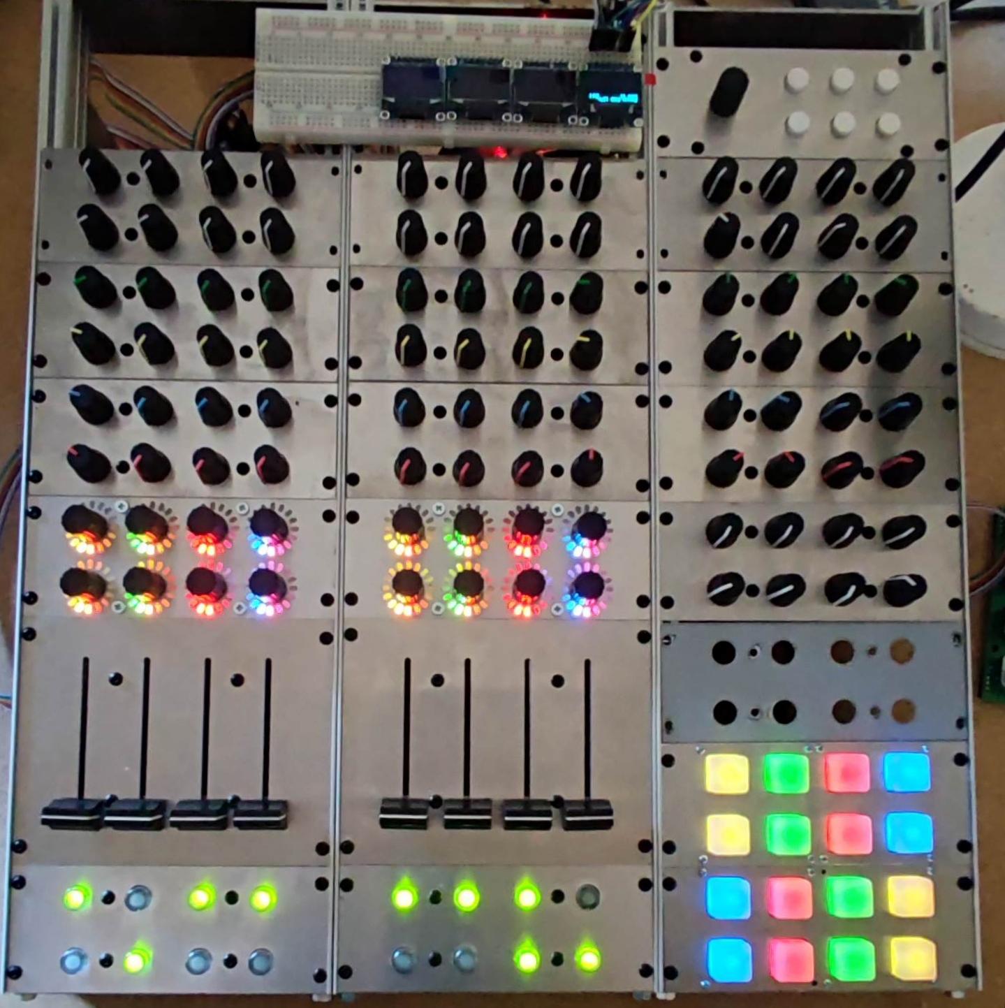
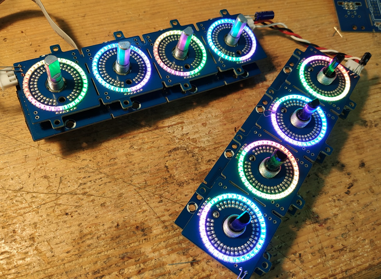
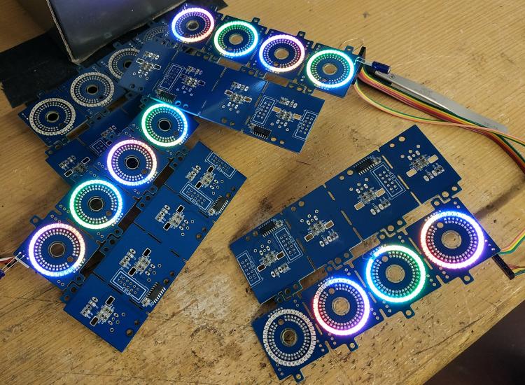
Hello, first of all thank you for your previous answers. I haven't fixed the problem with the pads yet. I'm focusing on another problem for now: with the LED rings. with 16 led ring of 16 led no problem. when I add more, the LEDs flicker. https://youtu.be/HyLkVeFtALw?si=gT09lbCxEwLRmHt8 I read here: http://midibox.org/forums/topic/21095-lre-4x1-breakable-rgb-led-ringrotary-encoder-pcb-bulk-order/?do=findComment&comment=184155 FantomXR had flickering problems, solved with a 10uf capacitor. Should I add a 10uf capacitor at the input of my LED ring cards? (as in the image below) (C129) To understand my configuration see the pdfs: LEDRING: https://drive.google.com/file/d/1XpDQBUE42IqXpXicO--B2gfIoNQDh5ga/view?usp=drive_link “power card”: https://drive.google.com/file/d/1NJ-H-QXD-tl9rU6nbYdEh2Q4jFqjWt6b/view?usp=drive_link I made a PCB that I call a “power card” that I supply with 5v 10 amps. The J2 connector of the "power card" is connected to J4b of core 32. Connector J44 of the first OLED card is connected to J3 of the “power card” Connector J45 of the first OLED card is connected to J4 of the “power card” Connector J44 of the second OLED card is connected to J5 of the “power card” Connector J45 of the second OLED card is connected to J6 of the “power card” etc.. Thank you
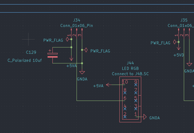
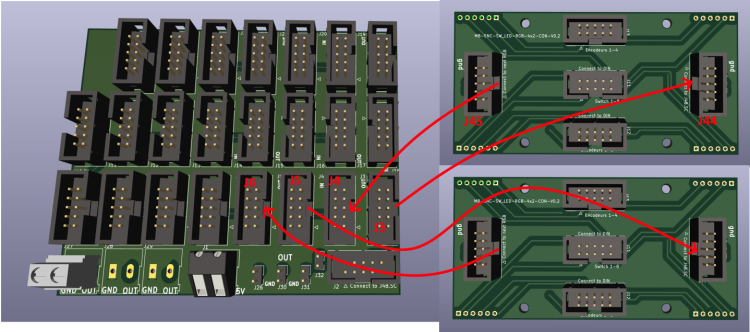 1 point
 -
Hi all , Was wondering about opening a KiCAD Section in the wiki? For tutorials , midibox libs etc... where should i put it? regards, JK Edit : A Frontpanel designer section could be useful too ?That's a soft that i think most of us use? Maybe create a "Softwares" Section?1 point
-
1 point
-
Hello, I have a rebound problem with the sparkfun pads, do you have an idea how to fix this? Hardware? Software ? Thanks The rest works fine
 1 point
 -
1 point
-
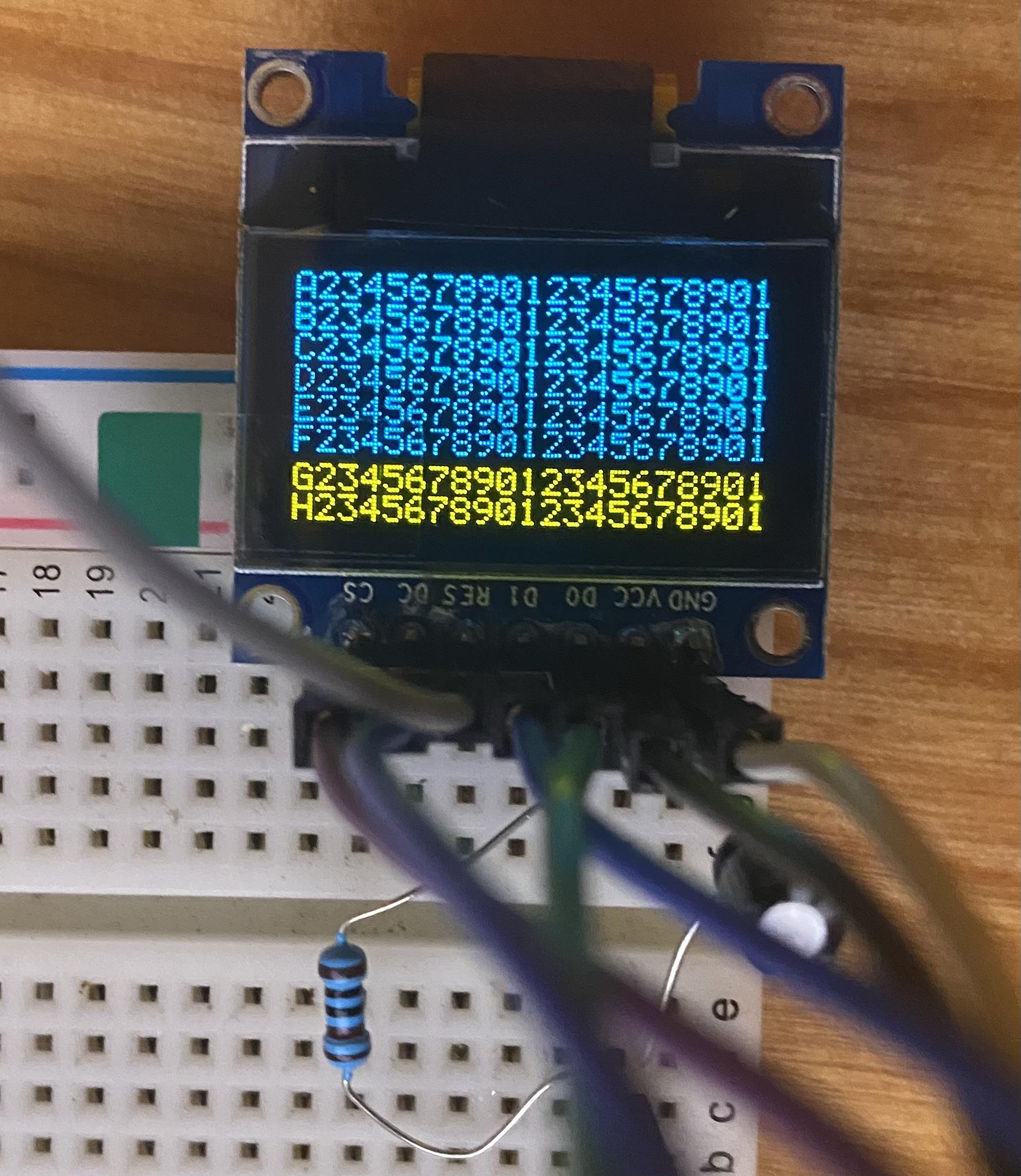
Oh, wow, I totally missed that! Thank you!!! I wasted an entire day rummaging around and didn't manage to see that :) Just in case others run across this: You want 4SPI configuration, not IIC like I have in the pic. The number of screens you have must match the configuration you set in the bootloader, otherwise you get noise, and won't be able to write to all the lines/columns Also easy to miss, but for the 1306 RES connection, you need to wire it up like this (again, connections on your 1306 PCB): GND -> 10uf cap -> 1k resistor -> VCC. Once done, RES will be tied to where the cap and resistor meet (like this) It wasn't clear to me how to actually use the bootloader for the STMF4 board, but it's essentially: Plugin your board as you normally do Open MIOS Studio Click Browse and choose the mios32_bootloader app (download here) Click Start. If it won't complete, try unpluging/pluging the board and trying again Unplug/plugin the board In the MIDI IN and MIDI OUT sections whatever app you had prior to all of this might be listed, but it doesn't actually exist (and it shouldn't). That's why you now see the error "No response...". The new app, MIOS32, took its place and you need to refresh to see it. Click Application -> Rescan MIDI Devices Click Understood in the pop-up (this will make your old app disappear, and the MIOS32 app show up) Change MIDI IN and MIDI OUT to MIOS32 Enter these one by one into the input box: (send a command to MIOS32 application). Keep in mind lcd_num_x must match the number you have chained: set lcd_type GLCD_SSD1306 set lcd_num_x 1 set lcd_num_y 1 set lcd_width 128 set lcd_height 64 store Yah. Bootloader is done. Time to restore your app in MIOS Studio: Click Browse and choose whatever app you want, like midibox_ng Click Start. Like the bootloader, if it won't complete, try unpluging/pluging the board and trying again Unplug/plugin the board Now for some test display data. Lets set some values for your SSD1306 OLED's in MIOS Studio: Click on Tools -> MIOS32 File Browser Click Create File Create some name like LCD.NGC Click Update Click on the file you just created Click Edit Text and add the following test example: RESET_HW LCD "%C" LCD "@(1:1:1)A23456789012345678901234567890" LCD "@(1:1:2)B23456789012345678901234567890" LCD "@(1:1:3)C23456789012345678901234567890" LCD "@(1:1:4)D23456789012345678901234567890" LCD "@(1:1:5)E23456789012345678901234567890" LCD "@(1:1:6)F23456789012345678901234567890" LCD "@(1:1:7)G23456789012345678901234567890" LCD "@(1:1:8)H23456789012345678901234567890" Click Save You should now have 8 rows and 21 columns of text. If you need to flip it 180 degrees, you can redo the steps above and add set lcd_type GLCD_SSD1306_ROTATED before you store.
 1 point
 -
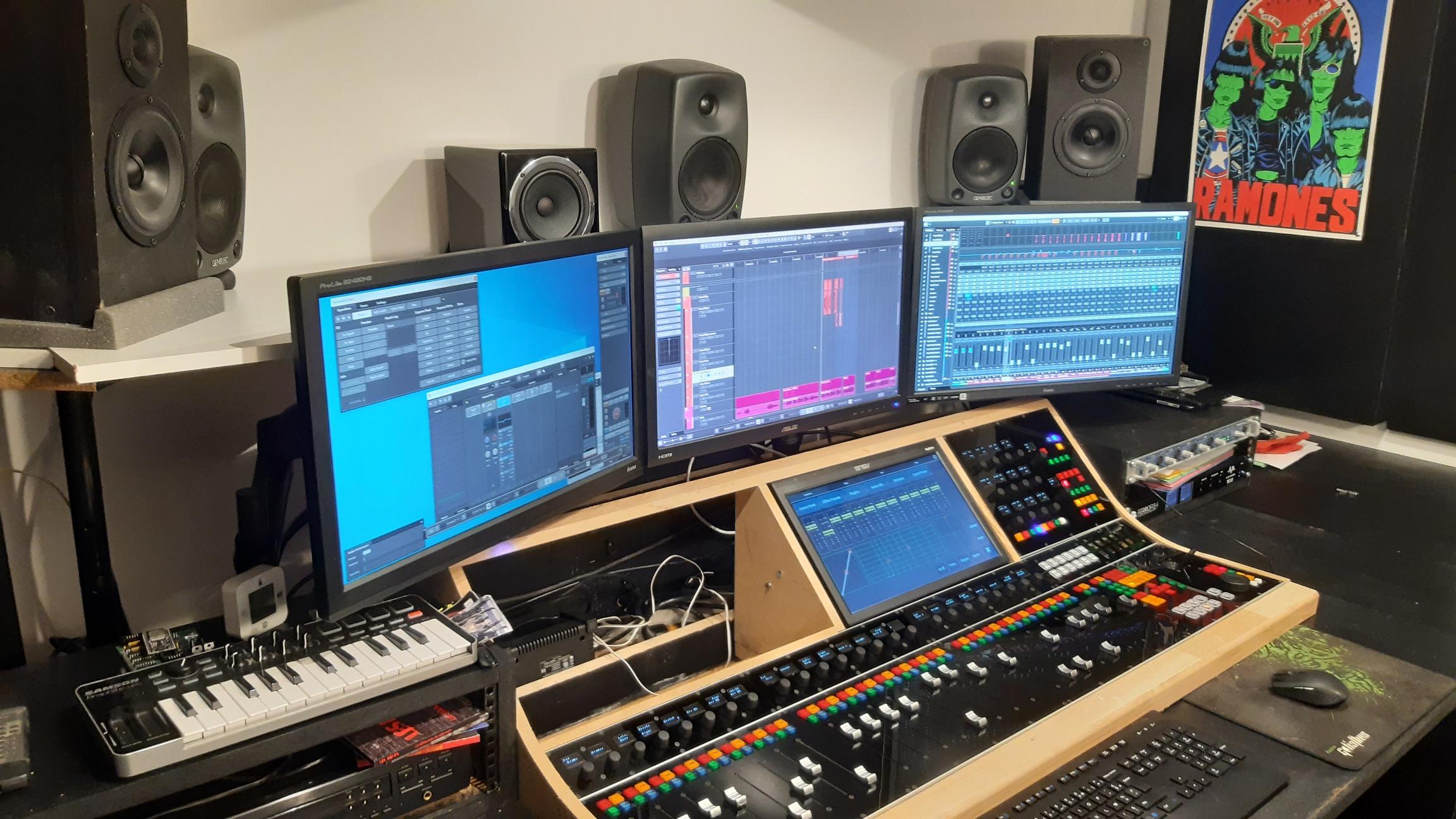
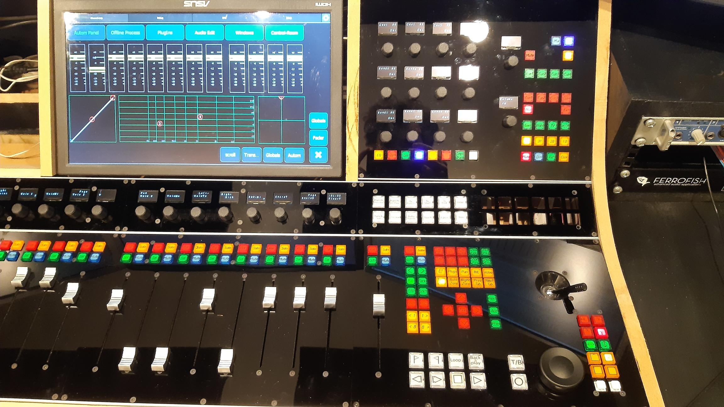
Hi Therezin, I mounted the monitor upside-down because of the viewing angle. This specific monitor has been designed to be looked at from above. It's actually pretty good from around 10° to 90°, but from 95° to 180°, the visibility is very bad. Therefore i had to reverse it so when i seat behind my desk, i'm in the good range. Let me know if this explanation is not clear enough, it's pretty hard to describe in a foreign language. Thomas1 point
-
Hi everyone! Quick update here. I finally finished my controller and installed it in my small control-room. Here it is. I really like the way it turned out, i'm working with it since 2 weeks now, and it's a real bonus to the ergonomics. It still have room for improvements but that was expected and i will continue to work on it in the next future. I'd like to thank everyone on this forum who helped me build this and a BIG thanks to TK and all the midibox team. Without this place I would have never been able to even start this project. Cheers, Thomas

 1 point
 -
1 point
-
@Hawkeye Thank you for the thoughtful replies. It is easy to think of future wishes and add ons but at the same time forget about how it would effect everything else. I love the Seq4+, very little I would change! And the fact that I can get into the code and try things myself is pretty amazing. That alone is a "feature" that very few seq's can boast. @flyweightIf I was looking for more humanized recordings I'd use the longer tracks with higher divisions OR the humanizer feature! Also, you can specify your own shuffle parameters, you may find something that gives you YOUR feel.. if you could analyze how your beats groove, you may just be able to create that groove as a template and there ya go. May be worth digging into. At the same time, your experience and learning from building the Seq is not lost if you sell it. You lost time, yes. I'm sure if you put it on the market it will sell pretty quickly. ~Steve1 point
-
Hi, Check or add the correct path in environment: Page 14 in the pdf Best Bruno1 point
-
Hi guys, I don't know the best for your project but I can explain what I did for the OLRE16. First is the MASK, it's black PMMA. Both sides are milled. I let some space between the leds on the pcb to keep some matters between the leds housing. Led size is 1.5x2mm On the other side(front side) there's some stripes which will fit inside the translucent PMMA, they will block the light between the leds, between the rings and between the rings and the oleds. . Note: the olre16 top pcb(ring) has no component on the top except the leds and the oleds. In blue are the back leds housing. In Red there are the holes. In Yellow, some stripes to block the light on the front, those stripes will fit inside the back of the translucent PMMA. The second part is the 'WINDOW', in translucent white PMMA, it's a LED special one, the same I used for the beat led window of the Seqv4+. The back part will fit inside the MASK, in other word the base of the WINDOW will receive the MASK's stripes, of course the WINDOW's pipes are in front of the MASK's holes. Then the Aluminum front panel comes to finish blocking the light and the pipes of the WINDOW will fit inside the panel, flush the surface. When they are coupled When coupled , assembled the thickness without the pipes height(front panel thickness) doesn't exceed 2.5mm Voilà! I don't know if it will help you and It's surely an "over-engineered" thing but this is the only solution I found, and it works. Best regards Bruno1 point
-
Hey people, thanks to @TK.! It's working great. Anyway I had still some flickering on the LEDs. As I stated above I left away the caps ... and this was the reason. I know have added a 10uF on the input and on the output-connector of the LED-rings and the flickering is completely eliminated! Great!! So, one core can handle a total of 10 LED (10*36=360) rings....
 1 point
 -
Hi everyone ! I experienced the same problem, and The Ancient One's solution works perfectly for me. I changed the 220R resistors to 68R for R21 and R22. Now the 9090 detects the signal without any issue. Thank you a lot Michael ! Théo1 point