rosch
-
Posts
705 -
Joined
-
Last visited
-
Days Won
1
Content Type
Profiles
Forums
Blogs
Gallery
Everything posted by rosch
-
@ssp: what are you building atm?
-

Mb6582 plus 4 SSM2044 VCFs - use of a passive 4 channel stereo mixer?
rosch replied to Hermes's topic in MIDIbox SID
the routing is done in the menu. eg you need 1/2 Aout_NG for a dual SSM board. the second core would then be connected to the remaining Aout inputs. at least that's how i expect it to work. i'll try to use SSM2044 VCFs and SSM2164 VCAs with the MB6582. that's of course all dreams of the future right now, haven't even completed the synth itself and only 2 working NG's and just one of each SSM boards finished. -
update: all sids are already spoken for! sold! thanks for your interest, guys!
-
hey guys, up for grabs are 8x SID 6582A i bought some time ago from Wilba (Megasales) they're still NOS, i didn't even open the tubes for cuddling... price is, like i paid, 30AUD per chip. no shipping limitations, but it's a good thing if your name has already been heard on the forum. they're the actual chips in the attached picture (edit: removed the picture) just PM me if interested
-
Yakuza - our latest song using NES, OPL3, and the SID
rosch replied to m00dawg's topic in Songs & Sounds
vinyl release? that would be cool! -
afaik no deadline so far, just looking for interest.
-
please post pics of the finished synth! looks promising!
-
yeah absolutely! btw there has been plenty of documentation at the beginning of this build about 2 years ago, for those interested in detailed pictures. very interesting stuff!
-
thanks for the confirmation about the switches!
-
great great work! are these 5mm LED's? i'm going to do the modulation matrix with those e-switch tact switches, instead of 6X6mm ones and i was wondering if the resulting greater distance of the led rows might reduce the perception as one unit. but that doesn't seem to be the case, judging from your panel. how big are these switches you used? beautiful!
-
sie haben auch unterschiedliche filterkondensatoren. aber man muss auf dem pic auch entweder 6581 oder 8580 firmware haben, also kann man pro pic (soweit ich weiß) nur eine sorte benutzen.
-
the core8 means it's the PIC18F... based 8bit core, versus the STM32 (the newer one), so that would be the same as on ucapps.de the CORE_V3 pcb. if you build a midibox 64 or 64E you'll need a PIC 18F452 for the core. i'm not sure what you're referring to when you say switchpots. normally you need the AIN (analog in) module to read values from analog potentiometers (a few can also be hooked directly to the core module) and the DIN (digital in) module for operating (digital) tactile switches (momentary on) and/or encoders. the number of modules depends on the number of switches. everything's described in detail on www.ucapps.de in the MBHP section.
-
the fm has a cool design. it somehow reminded me a bit of the old eighties computer game graphic style! well done!
-
awesome! heck of a lot of wiring.... yeah i'm also starting from base pcb alone, so that's my next step too looks great!
-
that's a cool price imo, and a class A occasion to grab one.... if i wasn't that broke atm
-
haha i did that too. unfortunately that meant not making any music at all for quite a long time, given that i'm an extremely slow builder. i've made an AVRsynth too recently, quite cool. @strat-1 nice style! the video was cool.
-
also, it's good to know the distance from the drill to the stand of the press, as this is the working range. some have a very small range, which can be annoying when you're drilling a lot of bigger panels.
-
Wilba seems to look quite skeptic, though but seriously,have you recorded any of it?
-
awesome!!
-
btw, i'm not sure if this bulk order is active at the moment. but you should be able to find out about it on the forums.
-
it's on the left below the list, like in that pic:
-
thanks, Thorsten, i got it working now! the soldering looked really clean, but i thought maybe there's a bad contact somewhere. so i went over the whole chip again, with flux and solder wick, after that it worked! i made the feedback tests, and all ports work fine in mios studio (haven't tried the strings yet, though) now it seems to me that the behaviour of the leds was actually normal. i've just tried normal midi use but i'll try to upload some firmwares tonight. really glad it's working, so far. thanks for your help!
-
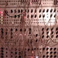
hm i've built another one, red pcb (i kept it all stock this time, with leds) 1st time i plugged it in the main led lit up (although not too bright) and windows informed me that a "USB Verbundgerät" had been installed and it would be better to reboot the pc, which i did. after that there was no main led on anymore. i tried to send some midi notes to a synth but failed. strangely, when putting the usb plug in, the following led sequence happens (video) actually, the smt soldering job seemed to have worked well & easily. but i might have messed sth up... could it be there's something wrong with the optos? (as only midi ports 1, 4 and 5 seem to light up on start (should they do that at all?) (or maybe somth wrong with some leds, duh?) so the main led goes off after half a second, but the power out pins show 4,98V still. wrecked? am i the midibox dummy?? edit: i forgot to mention, i used the same 6N138's and hexinverters from the old one, as i don't have any others here right now (order them today) http://www.youtube.com/watch?v=lNXZIR5u1PM&feature=youtu.be
-
you could also do that on a breadboard, if you have one. (or some cheap sockets on veroboard)
-
haha, just answered your pm