

Hawkeye
-
Posts
3,636 -
Joined
-
Last visited
-
Days Won
36
Content Type
Profiles
Forums
Blogs
Gallery
Everything posted by Hawkeye
-
@Antichambre we had no followup communications on the dustcovers, but got to a prinicpal agreement, so they should still be on the table. We'll get to it, when the dust (hehe) of the first UI kit and case sales settles :) Many greets, Peter
-
Thanks guys, all credits go to Andy (for the design), Adrian (for the case) and TK. (for the software)! Just wanted to inform you that filming of the second part of the video tutorial has finally started. It will still take a bit of time to get to a production length of another estimated 2 hours (or maybe 3 hours with case installation and wiring informations), but we're on it! :) When it's done and published, the UI kits are ready for sale, we're stocked up and received another batch of OLEDs from Taiwan this week. Have a great weekend! Many greets, Peter
-
 no problem, had strange behaviour on the gallery lately too. we might need a forums software upgrade soon! :) will try to fix it! Many greets, Peter
 -
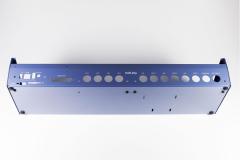
As promised, new photo session images for your consumption! :) The first image shows the installed blanking plate, that covers the holes that are necessary for rackmount mode, The second image shows the new "shade of blue", exactly as we wanted, it came out very nicely from the paint shop, thanks Adrian! The final image image shows everything in action with a new, maybe more eye-friendly color scheme. The activity matrix in this picture is currently in "TPD emulation" mode. There might be more modes later on, if we are allowed to add them to the firmware ;-). Hope you like it, we definitely do! :) Many greets, Peter
-

From the album: Hawkeyes MB stuff
This one uses a left-hand jog and activity matrix configuration, with green/red ("emerald green") color scheme! :) Enjoy and many greets! Peter -

From the album: Hawkeyes MB stuff
... now with labels, in the final shade of blue! :) Many greets and enjoy! Peter -
From the album: Hawkeyes MB stuff
including labels and an installed blinding plate, that covers the lower case options, that are available for optional rackmount mode. Fantastic work again by Hallik Engineering! Enjoy! :) Many greets, Peter -
@Rio blm8x8: minimal bitmask changes for the midiphy frontpanel matias switch superflux backlighting, conditional logic not active for a standard v4 tpd: added additional mode for slightly different midiphy frontpanel mini led matrices, conditional logic is not active for a standard v4 (+ optional external tpd) Many greets, Peter
-
@Rio no worries, it was only a "minimal invasive" patch that, as Andy said, would not touch or affect any non-midiphy SEQ v4+ variants. We visited TK today, thus the subversion commit comment "for personal discussion", which also had a smiley behind it. I tested the patch on my side thoroughly and expected it to be accepted by TK., but if it would not have been, it would have "cost" only a single subversion commit number to rollback. Many greets, Peter
-
As a small update to everyone interested - the new v4+ user interface hardware kit as been handed over to TK. today by Andy and myself. He had a look at a completed v4+ (pictures soon!), and will validate the UI boards once again from his side, we want to be sure, that all works nicely before sending out the new kit to users. I will start filming the construction video tutorial of the UI boards by next week. It will take a while until the tutorial is ready, but we will get there. Meanwhile, Adrian should be able to start production in bigger quantities, as the case looks really good! Many greets and have a great weekend! Peter
-
@the_duckchild Thanks, and which kind of color change LEDs are you thinking of, would you have a product link? The MB6582 only supports single color LEDs everywhere, but you can use different colors of LEDs in different sections of the frontpanel, although many people prefer to stay with a single color. If the "color changers" only require two pins and then internally do the color changing, then they could work, if they are standard 3mm LEDs, although your build would probably be blinking madness :) Many greets, Peter
-
Hi there, great build! I am not 100% sure, but I think, internal busses can not be used for MIDI Routing. Even if the interfaces are "there", i have not done it before and am not sure, if it is supported, TK. knows more! Afaik busses are only used for Transposition, Arps and Jamming and always effect internal other tracks only. I'd be pleased if someone would correct me, if i am wrong! But: what you can do is have a look at FX -> Duplication, this should fit your needs perfectly! I've used it successfully to send out same notes to two samplers on different ports, and you can also edit what is sent, to which port should be duplicated and how many channels should be active during duplication. This can be used for nice effects, like sending alternating notes to different synths and such :) Many greets, Peter
-
CEM3379 Stereo VCF assembled board
Hawkeye commented on Schrabikus's gallery image in Schematics and PCBs
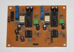 Nice one, and welcome back, Schrabikus! Many greets, Peter
 -
Looking good! :) Just out of curiosity, how many CC samples can you store on a track (resolution)? Will you support more inputs than one CC per track? I've recently found some unused memory on the LoopA and was thinking of limited CV support, too. But it will be a single CC per track only at limited resolution. So yours will be the dedicated machine for it, for clean filtersweeps and such, no competition there, no worries! :) Many greets, Peter
-
@jingo thanks for your interest, there are qualified builders around, maybe someone will contact you. We will have to get shipping of all parts including the case going first. But here is the good news: Adrian shipped the final/release version of the lefthand jog/JA case with printed labels to Germany, so we'd expect to be able to provide you with new images of the final unit next week. So we can compare if it came out like the label photoshop mockup provided earlier :). The next phase is a final "fit-test", to see if everything can be installed nicely, then Adrian can ramp up the production. If all looks good (which is expcted), the v4+ could be under your Xmas trees, we should be able to ship everything essential for the v4+ in November. Many greets, Peter
-
Looking good! :)
-
Play MIDI and mp3 at the same time on different outputs
Hawkeye replied to Tardief's topic in Miscellaneous
Hi and welcome! If you require normal audio output (not mp3, which is a digitally encoded format) in conjunction with synchronized MIDI note output, any DAW should be able to do it. The VSTs/VSTis would convert internal MIDI to audio ("through jack") and you could also have a plain "MIDI track" outputting the associated MIDI notes to any USB MIDI interface. What will also work in the MIDIbox context is to use a MIDIbox sequencer, output MIDI notes to any MIDI OUT, attach a synthesizer to that port via MIDI, grab its audio from its audio output port and the associated MIDI data from its MIDI THRU port. Have fun and many greets! Peter -
Hi Roel, congrats to the build, thanks for the confirmation that it mostly worked out without a problem and glad that you like the docu, can't wait to get working on the second part! :). If there is similar feedback from other builders regarding the cheaper 6N138 sockets, we will replace them in the BOM. Personally, I've not yet had problems with them, but you are right, you need to make very sure, that the IC legs are properly bent for them to fit nicely. Regarding the SD-card, can you try to format externally using your computer using FAT32 as a filesystem? If the micromatch connection is ok, you should then be able to use it in the SEQ. (You could use the MIOS studio filebrowser to verify it works and try to store files on the formatted card via MIOS Studio filebrowser). You can also partially test some of the PCBs that you built using MIOS studio, e.g. if you enter "play" (or "start", can't remember right now :)) at the console prompt, a backside LED should flash (like in the video right at the beginning when the unit backside is shown), the other backside status LEDs are yet unused - the v4+ software would need to be extended a bit to make proper use of them (should not be terribly difficult, i think we could indicate "BLM connected", "Gate" and "MIDI in" activity with the remaining three LEDs). Also, when the sequencer is playing, the first track imho is filled with some notes per default, so if you attach a synthesizer to OUT1, you should be able to confirm that the first port on your MIDI8 PCB works properly. There is no ethernet extension planned (or room for it in the case) - effectively "on board ethernet" was dropped after the LPC17 core generation and the introduction of the new STM32F4 cores. But i am sure, if there was enough demand, with a bit of tinkering, it should be possible to design an "out-of-the-box" solution, that might connect e.g. to the BLM port (also carrying power) or two classic MIDI ports (external power required then), which could provide ethernet forwarding. Until a solution like that is implemented, it should be possible to forward/route a MIDI pair to your old sequencer and use that as an ethernet bridge (even if it does nothing else and just sits in the corner :)). Have a great day and many greets, Peter
-
Nah, it's not enlightened, i mean the LEDs hopefully are, but us... not yet :) The RES-SD BOM resistor values (1k) came from the original wiki RES-SD docu and seemed to work out for my initial RES-SD tests with these LEDs. No big care was taken for total brightness equalization, just a look if moderate-brightness indication works properly. So, if there are updates to these resistor values, please shoot :). The resistor values listed in the shop for a 5V source were more or less trimmed by experimentation to achieve similar brightness for all multi colored LEDs, and primarily done to be able to take a good photo. As in this scenario the LEDs are a bit brighter and are driven "hotter" than for the RES-SD case, i also measured the LED currents to make sure, that no LED exceeded a two digit milliampare value. The recommendation should be far away from limits (being at 20mA or such). But, as the brightness curve of these LEDs is really highly nonlinear and the LEDs begin to light up at very low currents already, probably using the same resistors everywhere will not result in a totally different picture than seen in L-X-01 for example in the shop: In the end, and as Andy said, you've just got to test and fine-tune to your preferences! :) Many greets, Peter
-
Fully agreed, brightness perception is highly subjective! The 5V values were deduced on breadboard with a DMM measuring current @5V. The 3.3V values above were just calculated with an online tool from the 5V values and are not tested at all. Regarding SD-RES: the LEDs are efficient enough to light up as signalling LEDs with 1K resistors - we don't want to illuminate the room from the back of the SEQ :). Also, the "brightness curve" is highly non-linear. I.e. a such a 4x3x2mm green LED will surely light up already fairly brightly at 1mA, and will by far not be 10x "dimmer" than at 10mA. Many greets, Peter
-
@Antichambre Hi Bruno, Thanks for considering to use them, just plugged the 5V data in a LED resistor calculator, derived the "diode threshold voltages" and calculated a bit. While i can't live-test at the moment i'd recommend to test with these values: (Edited) 120R@3.3V for blue 150R@3.3V for white and green 180R@3.3V for orange 220R@3.3V for red The LEDs are efficient, most are relatively bright already at 2mA, will saturate in brightness somewhere below 10mA, you can definitely test with a variety of resistors for your desired target brightness. Many greets, Peter
-
Thanks jaytee! :) You still have a beer on my tab, say a word, whenever you are near Munich! Many greets, Peter
-
@rbv2 if you have a lot of synths hooked up to multiple sequencers (hardware or DAW), as mentioned above, the best way to do it would be to use one big MIDI router to connect everything to :). Another not-so-bad idea is to use MIDI-THRUs directly on your v4(+) to multiply each of your OUT ports with only a single "hex inverter". That method is cheap, and adds only minimal and uniform latency. If you use the eight output ports of the SEQ and multiply them with eight quad MIDI thrus, you could connect up to 32 hardware synths with really little latency and best MIDI signal integrity while still being able to use USB to be able to connect everything via DAW additionally with just a bunch of SEQ MIDI routes. By chance, Andy has designed such an affordable MIDI-MULTI-THRU board, that should be available still this year :). Many greets, Peter
-
@ilmenator no worries, we are planning on releasing the schematics, we are the good guys! :) Also be assured, that In this case "priority" really is that, we have to still validate the new UI boards, adjust configuration for left hand / right hand jog models, create the second/final soldering/build video tutorial, slightly modifiy the firmware for the new activity matrices, and have a dozen other little tidbits on our todo lists. It is just a lot of work, and the release of the schems is not being on the top of the list. As we have normal day jobs and families, these are all time-consuming "after-work" or night activities, deeply cutting into the hours normally allocated for sleep, atm :). @eptheca yes, technically you are automatically running a "v4+" with any stm32f4. It is caused by a code preprocessor "define" looking for the processor variant. This is for simplicity, so that only a single firmware .hex is needed for any stm32f4. Nevertheless, you won't be able to use the new v4+ UI features until you enable the "antilog panel" hwcfg section to benefit from its features. We have no problem whatsoever to call the v4+ officially "midiphy SEQ v4+", if it helps to differentiate things. For me, the only important point is that "v4+" is in the name, because that defines the hardware capabilities of the unit, that the software can rely on. Best regards, Peter
-
Hi Hal, thanks for asking :) Regarding the questions, Bruno already answered the part, that midiphy is the name of the shop. As we should also have another MIDIbox based sequencer called LoopA as an "essential kit" in the shop hopefully soon, it would therefore be best to keep the name of "MIDIbox SEQ v4+" or "midiphy Seq v4+" or whatever you can think of, as long as it contains the v4+. :). That "plus" stands primarily for a general user interface improvement, designed by TK. and Andy over the last two years or so (see old thread). But the "midiphy Seq v4+" additionally also brings a new case solution, with the case being designed by Hallik Engineering, especially for this hardware, so all fits nicely in the box and will not take away too much room. The v4+ also has really great mechanical-keyboard-style switches, nice OLEDs, two mini LED matrices and lotsa bling :). Also, it should be easy to source/order, with only two orders in total required. As stated before, we do all of this, as we want to push MIDIbox and not enrich ourselves, we try to keep the prices moderate. Midiphy as a shop will also be trying to "host" other interesting MIDIbox user projects as well later on, so that interested users can get easier access to other awesome developments. To answer your other questions: * yes, you can reuse all your old v4 PCBs (as long as they are STM32F4 based) to drive the new UI, but they probably would not fit in to Adrian's case (Hallik Engineering). * yes, you should be able to reuse the TPD and BLM 16x4, if you attach it via the Line Driver expansion board, build a Line Receiver module and attach the BLM/TPD to the SRIO of the LINE-RX PCB. If you build your own (bigger) case, the line drivers might not be required. * Adrian has designed the v4+ case and spent lots of hours and quite a few (costly) iterations and he has the last word, what should be be public. Personally, I would vote for a publicly available "cutouts DXF", that contains the required holes in the frontpanel, so that users with other core PCBs or another intended case can create their own case while being sure to be able to mount the OLEDs, the two LeMEC boards, the new JA board and the mini matrix properly. But Adrian has the last saying in this. In the end, exactly as Bruno suggested, the v4+ is "just" a major user interface improvement! Some features of the v4+ will be instantly available on your old v4, but of course the expection are the hardware-centric improvements like the new selection model and the mini matrices. It is likely, that "v4+" designation in the config file defines an "expected set of well-known hardware capabilities", that can then be used by the sequencer app. So, while i expect the firmware itself to stay identical at least for a while, defining "v4+" in the configuration will (for example) switch to the new selection model and require the new UI hardware. Many greets, Peter