Search the Community
Showing results for 'STM32F4'.
-
I finished my build today, turned on my SeqV4.... some LEDs lit up, and there are solid top rows (black bar) on the LCD displays. There is a red LED flashing on the STM32F4. What's going on? I built my core and tested the discovery board months ago with LCDs attached. Successfully set up, read SD card, screens displayed as expected. I haven't turned on the core since then as I've been focused on enclosures and other aspects of the build. Now today, I assemble the enclosure with my CS board, two MIDI I/O, one Quad IIc, and one Line Tx. I removed the USB Power jumper and connected this 5V DC/DC converter that was recommended to me by another SeqV4 builder https://www.adafruit.com/product/1385 The AC adapter I used was 7.5V/2A. When I turned it on, I got the results described at the top of this post. I powered off, disassembled, and tested the output of the converter which measured 5.27V. Next, I replaced the USB Power jumper, disconnected all peripherals except the LCDs, and powered up using the USB port. Same result, core won't boot. Could the 5.27V supply have damaged the discovery board? Do these symptoms sound indicative of some other failure or user error? Thanks so much for any help!
-
I have some midibox kits lying aroud, but no plans.. It is: a fresh STM32F4 core a core kit from Smash TV plus the pcb with all parts two midio part kits, also with pcbs They are here in .NL. Asking price is €125 including shipping in EU. Or shoot me an decent offer if you wish..
-
hi i cant find in the documentation/remember/no-search-results: which pin on the discovery board i have to solder a cable and a switch, to get into boatloader mode with a switch from the outside of without opening the midibox... thx for help
-
Hi All, I've got an stm32F4 and a speakjet chip knocking around, so I thought I'd try out the speakjet synth for mios32 in mios32\trunk\apps\synthesizers\midibox_sj_v2. . Unfortunately, the schematic in the svn repo for the app. is for the lpc core module, looking at the schematic compared to the lpc module pinout, if I've got this right, the speakjet chip connects d2,m0,m1,rst to J10.d3, .d2, d1 and .d0 and the speakjet rcx pin connects to J5b.A7, will the midibox_sj2_v2 app. work if I connect the respective pins as they're laid out on an stm32F4 (pe8,9,10,11 for the J10 pins and pb1 for the j5b.a7-rcx connection)?
-
I'm building an NG as a central controller for several synths, so that I'll be able to control parameters for a bunch of synths using one NG interface. Right now I'm thinking the controller will have two 4x20 LCD displays, with 16 or 32 encoders, and about 40 buttons. Is there any real advantage to basing a MIDIbox NG controller on a STM32F4 core? Or could I use an LPC17 core without any real difference in performance?
-
Hey all, I finally got a Discovery board and managed to get the MIOS bootloader installed on it, but when I flipped the board around after connecting PA9 to the 5V pin, nothing. The computer won't even recognize that anything is plugged in. Is there anything I can do to fix this? I'm running Windows 7 64 if that makes any difference.
-

STM32F4 SDCARD Reading CID failed with status -256! Solved
gerald.wert posted a topic in MIDIbox SEQ
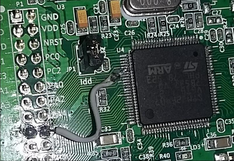
I had been getting the following error from the terminal when trying to access the sdcard on my STM32F4 core: [[35355.231] SD Card Informations [35355.231] ==================== [35355.231] ERROR: Reading CID failed with status -256! [35355.231] ERROR: Reading CSD failed with status -256! [35355.231] [35355.231] Reading Root Directory [35355.231] ====================== [35355.231] SD Card: not connected [35355.232] Failed to open root directory - error status: 12 [35355.232] [35355.232] Checking SD Card at application layer [35355.232] ===================================== [35355.232] Current session: /SESSIONS/DEF_V4L [35355.232] File /SESSIONS/DEF_V4L/MBSEQ_B1.V4: doesn't exist [35355.232] File /SESSIONS/DEF_V4L/MBSEQ_B2.V4: doesn't exist [35355.232] File /SESSIONS/DEF_V4L/MBSEQ_B3.V4: doesn't exist [35355.232] File /SESSIONS/DEF_V4L/MBSEQ_B4.V4: doesn't exist [35355.232] File /SESSIONS/DEF_V4L/MBSEQ_M.V4: doesn't exist [35355.232] File /SESSIONS/DEF_V4L/MBSEQ_S.V4: doesn't exist [35355.232] File /SESSIONS/DEF_V4L/MBSEQ_G.V4: doesn't exist [35355.233] File /SESSIONS/DEF_V4L/MBSEQ_BM.V4: doesn't exist [35355.233] File /SESSIONS/DEF_V4L/MBSEQ_C.V4: doesn't exist [35355.233] File /MBSEQ_C.V4: doesn't exist [35355.233] File /MBSEQ_BM.V4: doesn't exist [35355.233] File /MBSEQ_HW.V4L: doesn't exist or hasn't been re-loaded [35355.233] done. I checked around on the forum and had seen a lot of people having issues with wiring , the card slots and the format on the cards. Mine turned out to be bridged pins under the LQFP100 on the STM32F4 board. Here are the relevant pins if you are having issues as well: LQFP100 P1 PA5 30 15 PA6 31 18 PA7 32 17 PB2 37 24 Here is J16 looking down on it _________ | VS --- VS | -------> to ground | VD --- VD | -------> 3.3V (the STM32 actually only puts out about 3 volts) SI SO | SI ----> PA6 SO ---> PA7 | SC --- SC | --------> PA5 | RC2 RC1 | RC2 --> PD11 RC1-->PB2 (RC1 goes to the onboard SDCard reader or a card on J16 if there is no card in the reader ---------------- RC2 is for a second Card and not needed for most testing. I figured the board was already messed up so I decided to try fixing it. Those pins are super small and hard to work with. There was a dead short between PA6 and PA7 I was able to lift pin PA6 and cut the trace with a razor blade and solder a jumper directly from the pin to PA6. I would think this error would more likely happen from a solder bridge elsewhere and the STM should pass QC. The pins are pretty easy to test as they go straight to the ARM Processor. The also nicely went in order down the side. PA5 was pin 5 on that side of the chip. The white silkscreen on the board makes it a lot easier to keep track of the pins they are marked every 5 pins. The jumper might look a like it is crossing things in the photo but the pin is bent up and out so there is plenty of clearance. I tried solder wik, reflowing the pins, my hot air rework iron, cleaning between the shorted pins with a razor blade, and even removed the header pins hoping the short was there before lifting the pin but nothing else worked for me.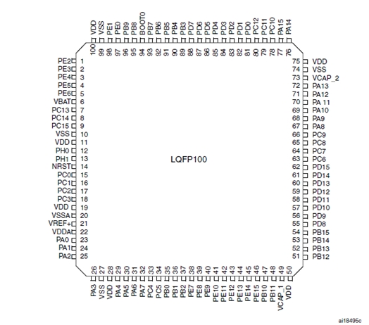

-
Heeft iemand een idee waar je deze in Nederland kan krijgen? Via Distrilec en Mouser betaal je een tientje verzending, en dat vind ik nogal veel voor een onderdeel van 3 euro. Of wellicht heeft iemand er nog eentje liggen die kan overnemen?
-
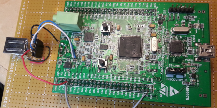
I received my first F4 Discovery board from an Chinese ebay seller along with some excellent value LEDs and an LCD display this week. The F4 was able to be flashed with it's booloader through the ST link as per TK's instructions. It was when I attached the target USB connection that didn't work, that I spent quite a few hours to sort things out. I found: various short circuits under CN5 (the target USB port) USB data line short circuited by a solder bridge. SMD capacitor open circuit (not properly seated) Worst of all(!): CN5 was the wrong kind of connector for this PCB. It was a micro USB receptacle, sure, but one designed for a PCB such that in this case the logo on the cable plug faces down. The result is that all the terminations are made in reversed order(!!!) It took me by surprise after many confused hours. For example why was the Vbus sitting at -0.7V rather than +5V? (Because with power attached backwards the 5V rail was being clamped by the diode action of a nearby logic chip, which was getting warm, btw) Happily, and perhaps miraculously the board is now working (at least the functions that I will be using). I removed the CN5 connector with a hot air gun (after carefully wrapping the PCB in foil to protect the rest of the board from the heat). I soldered 4 wires onto the PCB for the USB connector mounted on the baseboard.
.thumb.png.f0e98c2b6fca00e6f2199b857bfa2979.png)
-
Hi All, I hope this is considered the correct part of the forum for this. I am a novice midi to MIDI and a general tinkerer. Not much of a musician either.... I saw the Goom Synth build on the STM32F4 and thought it looked like good cheap fun. I have managed to procure the board, install MIOS32 and upload the synth "project.hex" without too much stress. I don't have a good way of playing the synth (no keyboard ATM) so long term I wanted to try using an old Motorola Xoom as a touch interface, similar to "ttfshtt" or "AVLG". Currently I have managed to connect to the tablet using the Cntrlr interface created by "Synthy" (for which I am very grateful) on both Win7 & Ubuntu Studio. All the above was done with two USB cables attached which is a bit of a pain, so I tried the PA9 to 5V trick. Although the board appears to power up, I don't get the pulsing LED LD4, and LD1 (Com) flashes instead of being solid red. By accident I have just discovered that if I plug in CN1 temporarily whilst CN5 and the jumper are in place, I can get the board to boot. Interestingly, it is more complex than just getting power on the CN1. If I plug the board into USB power block whilst connected to my laptop on CN5, it won't boot. I needs a laptop USB to trigger the board (hope that makes sense). Has anyone experienced this and have a cure? it is a pain at the moment, and I would like to try playing with MIDI commander on either my Samsung Galaxy, or Motorola Xoom as a control interface. (currently I have managed to at least see the Goom in MIDI commander with my Galaxy and a USB OTG cable). The board I bought from Farnell is the "STM32F407G-DISC1" which seems to be an updated (but I can't tell how) version of the STM32F407. Any thoughts appreciated.
-
Hi TK, as stated in another thread, the STM32F4 used on the latest core seems to be an "end of life" product. Is there any replacement you plan? Thanks, Chris
-
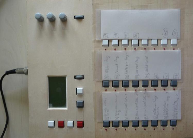
Sehr geehrter Herr Klose, geehrte Damen und Herren, im Zuge einer Midibox-NG- Applikation arbeite ich seit längerem an der Midifizierung einer alten Digitalorgel. 1. Digitalorgel: 2 Manuale (61 Tasten), das Pedal (30 Tasten) und Koppelschalter liefern seitens der Orgel -12V bei gedrückter Taste. Die Taster sind im geöffneten Zustand über 2 k Widerstände seitens der Orgel geerdet. 25 Registerschalter liefern 5 V Schaltspannung, im Ruhezustand beträgt diese Spannung -5 V. Das Pedal hat Reed- Kontakte. Damit die Orgel jederzeit wie zuvor gespielt werden kann, habe ich die DIN- Module mittels einer Pegelwandlung über Optokoppler angehängt, was den Vorteil hat, dass sich keine direkte Spannungskopplung ergibt. 2. Computer: Der Orgelcomputer ist ein Windows8.1- PC, verfügt über 12 GB Ram und 2 x 4- Kern Prozessoren (Intel Server- Board). Als Orgel- Software setze ich GRANORGUE (GO) ein. Als USB- Treiber verwende ich den GM5- Treiber. Die Midibox-NG-Applikation ist über eine 10m lange aktibe USB20- Verlängerung angeschlossen. Als Testcomputer verwende ich daneben einen PC mit Windows- XP SP2 (2GB Ram, Dual Core) und ebenfalls den GM5 Treiber. 3. Midibox-NG- Applikation (Basisboard plus STM 32F4- Kontroller): Daten laut MIOS Studio: OS: MIOS32 BOARD: MBHP_CORE_STM32F4 App.: Midibox NG V1.032 Flash-Mem.: 1048576 Bytes Ram: 196608 Bytes LCD-Type: 0x83 - GLCD_DOG 8x1 bzw. 128x64 Es ist eine SD-Card über einen micro- SD- Adapter angeschlossen Es werden folgende Anschlüsse des Basisboards verwendet: 3.1. DIN / OUT: DIN 1: 24 Taster im Controller (kurze interne Verbindungsleitung) 1 Encoder Wheel DIN 2: Pedal (ca. 50 cm Verbindungsleitung vom DIN1) DIN 3, 5, 6, 7: Manuale, Koppler (jeweils ca 10 cm zwischen den DIN- Modulen) DIN 4: Registerschalter DOUT1 24 LED im Controller (als Rückmeldung / Statusanzeige der DIN1- Taster) 3.2. Analogeingänge: 3 x Potentiometer (interne Verbindung) LED- Panel (interne Verbindung) USB- Device (Die Spannungsversorgung erfolgt über den USB- Bus) 4. Meine Bitte: Bitte gewähren Sie mir die dringend benötigte Hilfe und Unterstützung bei der Beseitigung des nachfolgend beschriebenen Problems, das ich bisher nicht zu lösen vermag. Was für mögliche Ursachen Fehlerquellen erkennen Sie, was kann ich bzw. sollte ich ändern, überprüfen um den Fehler zu beseitigen. - Störimpulse auf den Leitungen zwischen DIN und Manualen ? - Störimpulse auf der Versorgungsspannung der NG- Applikation (USB- Versorgungsspannung) ? - Verwendung von mehr als 4 DIN- Modulen; erforderliche Maßnahmen ? Hinweis: Die NG verwendet für den DIN- OUT Anschluß einen 74 HCT 541 Treiber. Ist hier ein insbesondere der 100 Ohm Widerstand zwischen den RC1 bzw. RC2 Clock- ausgängen und der DIN- Chain erforderlich ? - Software- Entprellung; prellen die Manualkontakte stärker als vorgesehen, ist die Entprellogik zu langsam, zu kurzes Zeitfenster ? - Abschaltung aller nicht benötigten Funktionen, um Rechenzeit zu sparen ? - Generelle Präventionsmaßnahme: Kann man zB durch Konfiguration die NG dazu bringen ein NoteOff grundsätzlich zweimal senden, und / oder nach jedem erkannten NoteOn individuell für den zugehörigen Eingang mehrmals in kurzen Abständen zu testen ob das Signal aus ist und dann ein NoteOff zu senden ? - Kommt auf dem USB ein Übertragungsprotokoll mit ausreichender Fehlersicherung zum Einsatz ? Nebenbei bemerkt: Der Hänger beim Up- oder Download, wie er im Forum bereits beschrieben wurde, tritt auch bei mir sporadisch auf. 5. Mein Problem, meine Analyse- und Abhilfeversuche: Beim ersten Spielen der Virtuellen Pfeiffenorgel (VPO) blieb in grösseren aber auch kleineren Abständen 1 Ton im Pedal angeschaltet, das NoteOff- Signal bzw. das Loslassen der Taste wurde wohl verschluckt. Das hatte ich in den Tests zuvor nicht bemerkt. Die Midibox- NG- Applikation war über ein USB- Kabel mit ca. 1,5 m Länge angeschlossen und über USB mit Spannung versorgt. Nun dachte ich das könnte insbesondere an dem relativ langen Flachbandkabel nach unten liegen und änderte die Zuordnung so, dass oben die Anschaltung direkt am ersten DIN- Modul (DIN2) liegt (ca. 1,5m Flachbandkabel). Wegen Umpositionierung der Lautsprecheranordnung wurde die Midibox- NG- Applikation über eine aktive USB- Verlängerung von 10m angeschlossen. Beim weiteren Spielen der VPO ergab sich der Fehler nicht mehr im Pedal, sondern im oberen Manual. Es werden bei wiederholten Versuchen die Töne von bis zu 3 verschiedenen Tasten, die alle am selben Schieberegister des DIN5 / demselben Optokoppler hängen, nicht abgeschaltet, aber in jedem Fall nur ein Ton gleichzeitig. Ich kann leider nicht sagen, ob es sich vor und nach der Änderung der Zuordnung um dasselbe Schieberegister handelt, oder denselben Optokoppler- Chip. Die Verwendung eines USB- Adapters mit zwei Steckern zwischen PC und aktiver Verlängerung (falls die NG- App zuwenig Strom bekam) nützte nichts. Bei genaueren Analysen stellte ich nebenbei fest, dass die Registerschalter im Ein- Zustand zum Flackern der Stop- Buttons der VPO führten, Es stellte sich heraus dass die Optokoppler bei 5V nicht stabil schalteten, was ich durch Erhöhung des Schaltstromes erfolgreich beseitigte. 5.2. Detailtests der DIN- Module und der DIN- Funktion Nun untersuchte ich alle Lötsellen des den Problemtasten aktuell zugeordneten DIN5 und des dazugehörenden Optokopplermodules mit der Lupe und reinigte die Platine in verdächtigen Bereichen. Danach machte ich Spannungs- und Widerstandsmessungen, die waren in Ordnung. Test mit speziellem Taster, der 8 Eingange gleichzeitig einschaltet: Nun führte ich die nachfolgend beschriebenen Tests mit dem Testcomputer durch, mit kurzem USB- Kabel, an die NG- App ware neben dem internen DIN1 nur das verdächtige DIN angeschlossen. Ich verwendete zum Test einen Taster, der beim Druck jeweils 8 Eingänge aktiviert, zuerst vor dem Optokoppler, danach direkt am DIN- Modul. Jeweils nach einigen Tastendrücken in unterschiedlich schneller Folge, hörte ich, dass von Grand Orgue nicht alle 8 Töne gespielt wurden. Das war für alle 4 Stecker des DIN- Moduls entsprechend. Analyse der ankommenden Midi- Befehle Nun analysierte ich die am GM- Treiber ankommenden Midi- Signale zunächst mit dem Tool "Midiox", weil man damit einen guten farblich differenzierten Überblick hat. Es ergab sich folgendes: Fall 1: Die meisten Tastenimpulse (Drücken und loselassen) liefern 8x NoteOn und 8x NoteOff. Fall 2: Ab und zu liefert der Tastenimpuls neben den 8x NoteOn 2x hintereinander 8x NoteOff Fall 3: Ab und zu liefert der Tastenimpuls zuerst nur für einige der 8 Eingänge NoteOn, (zwischen 1 und 4 Eingänge), der Rest NoteOff. Nach ca. 10 ms (Midiox- Timestamp) kommt dann 8x NoteOn. Danach 8x NoteOff. Fall 3.2: Ab und zu jedoch werden beim Tastenimpuls im Vergleich zu Fall 3 die fehlenden NoteON- Kommandos verschluckt, es folgt nur 8x NoteOff. Fall 4: Sehr selten liefert der Tastenimpuls auch 8xNoteOn 2 mal hintereinander und danach 8x NoteOff. Nun reduzierte ich in der Definitionsdatei die Zahl der Schieberegister auf 4, worauf die Häufigkeit der Fälle (2-4) abnahm, insbesondere der Fall 3.2 ! Bei drei weiteren Testsequenzen analysierte ich direkt die von MIOS- Studio protokollierten Signale, mit demselben Ergebnis. Das festgestellte „Übersehen" von NoteOn- Kommandos kann in meiner Anwendung toleriert werden, jedoch wäre es wichtig, die Ursache dafür zu kennen. Auch ein selten übersehenes NoteOff muß jedoch unter allen Umständen vermieden werden. Ich konnte in meinen Tests nicht feststellen, dass / ob die NG erforderliche NoteOff Kommandos im Zuge des Loslassens einer Taste nicht sendet. Für Ihre Unterstützung und Mitwirkung vielen Dank im Vorraus. K. F. Mayer dintest-seq2_conf f 8 DIN.doc dintest-seq1_conf f 4 DIN.doc


-
I'm using my seq V4 (with PIC core) live from quite some time. I think it's time for a core update, and I want some advice for choosing the core. As title says, based on your experience with the cores, what core should I choose ? Thank you for your help.
-
Hi, just wondering if the I2S DAC module still useful with the new core32 STM32F4?
-
Another question about the MBHP NG platform: How to connect the Motorfader NG to new core32 without using MIDI (STM32F4)? Wich best way and protocol to use? (as well as MIDI I/OS on new core are already quite "pin-loaded") thanks in advance, Jerome
-
is there any Driver-code out there - in the MidiboxWorld - to use the onboard Audio DAC for CV? (0-127) i just need it for Velocity Control for the Accent of a TR606 which need a Voltage from ~4V to 15V (a little scale with an OP amp should do the trick hardwareside - i think) In the past i have done Accent with a Shiftregister, 8 Varistors and a Transistor... worked well, but steppy. thx phat
-
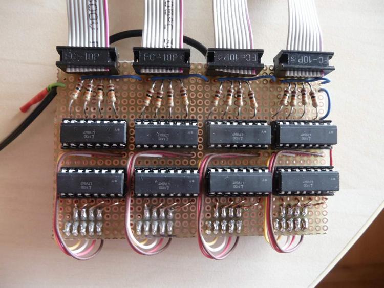
Hi Community, First, the midibox seq was my first DIY project, i'd like to thanks all of you, super project that gave me the fever of building hardware: an addiction is born :-) I read you a lot, and all is thanks to you. I was sequencing using a korg EMX (bad...!!), what a progress with this super Midibox Seq ! Almost all working good : STM32F4, 2x Midi I/O Module & Wilba Frontpanel. I want to add a Quad IIC module but here start the problem.. The IIC ports are not detected (Mios "System" and IICX * in the sequencer). It doesn't seam to be a connection problem (plug on J4A) : - 5V between Vd and Vs of the Quad IIC module - continuity between pin 7 of each PIC16F88 of the Quad IIC module and PB11 of the core (SD) - continuity between pin 10 of each PIC16F88 of the Quad IIC module and PB10 of the core (SC) I verified all solders on each module (Quad & Core), all seam good. The components are the rights ones too. I use the last version of the soft (V4.090), all Midi I/O ports working, no bugs detected. I don't understand why it doesn't work .. remain IIC ports not detected, and no LED working neither. Someone maybe have had the same problem ? Or can tell me what kind of test I can do to find the error ? Big thanks (and big respect) again for Midibox. Kind and warm regards Fanch
-
So I noticed that despite the STM32F4 having 192k of RAM, I could only have application code (plus MIOS32 of course) allocate up to about 128k. I found this by increasing the heap size until the app wouldn't link, and then checked the size of the larger arrays used in MIOS32 and my application. Since my application uses dynamic memory allocation, having the heap be as big as possible is critical. I found that the stack position is defined in STM32F407VG.ld, explicitly as _estack = 0x20020000, with a comment saying this is the end of the 128k RAM on the AHB bus. What does this mean? Why can't we use the remaining 64k of RAM? I tried changing this to 0x20030000, and (predictably) the application refused to start. So how would it be possible to get access to the remaining RAM? Edit: I found the other 64k of RAM, evidently it's in a separate section at 0x10000000, and I think it can't be accessed by DMA (which significantly limits its usefulness for many applications). I thought switching from LPC17 to STM32F4 would get rid of the memory segmentation issues, but I guess not. In any case, how do I get static/global variables allocated in that segment?
-
I've been browsing for a STM32F4 board and noticed different boards. Are they all be OK for midibox projects? Is there only one board we should use.? here's some examples. STM32F411 STM32F407, STM32F417 Looks like they use different MCU's and have different voltages. One is cheaper than the other.
-
Hopefully TK can give a diffinitive answer to this question.... If a MIDI IO module is connected to a STM32F4 core via J11E what is the voltage level of the MIDI out signal on the MIDI IO module? The discription of the jumpers on the PCB on the STM32F4 core page indicates that it's 3v. Is this correct or is the MIDI Out signal 5v?
-
 My reply to: Does this have slides, like the original design?
-
Hi, I just finished building a CORE_STM32F4 with a MIDI_IO Module. It's connected with a MB909 MK-IV board but this is another story. I've noticed that 3V output, VDD output are @ 3V... I'd expect 3.3V ... By the way I'm looking into this because I've having trouble with the LCD: it's unstable. The best way to replicate: hold EDIT button, it makes at lot of message on the SPI, after few seconds the DOGM display becomes full white. The core is supplied with a 2A PSU. The sofwatre doesn't crash, can see SPI messages after LCD "crash". Anyway, the question is: 3V core pin, VDD core pin: are they normal @ 3V or they should be @ 3.3V (at least VDD @3.3V) ? This document is confusing me: http://ucapps.de/mbhp_lcd.html this PDF: mbhp_lcd_dogm128_mios32.pdf it talks about the 3.3V but it's unclear where I can get it on the STM32. Thanks
-
From the album: eptheca
-
From the album: eptheca
-
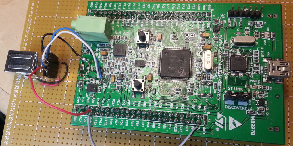
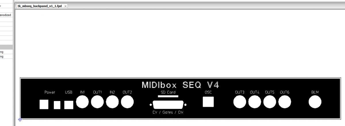
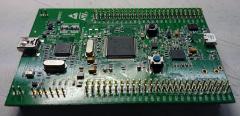
Finally ... the STM32F4 board arrived yesterday ... mios for seq v4 installed ...
Now the big soldering can start ... step by step


.png.ce10e7c2c9d3e5b7b02a64bc05fc1fea.png)