Search the Community
Showing results for 'STM32F4'.
-
Hi all, Thank you for all your advice and input... this was one of those times where doing the same thing multiple times yielded different results , and I still don't really know why, but I will explain the steps I took below just for anyone else's future reference...( Its worth noting that I had a couple of days when the forum was down, so I was kind of scrambling around outside of the steps recommended here ) I got to thinking maybe my USB drivers were causing the connection issues between my midibox and the MIOS Studio ...so I downloaded and attepmted to install the drivers (however I note that they say they are NOT related to the F4 board that I seem to have... and they didnt seem to like to install on my Windows 10 PC ( install ended in an error) BUT I do wonder if this action may have caused the native drivers to refresh somehow... as the next time that I plugged in I did it in this exact order 1. laptop on 2. hold down blue bootloader button on the board ( I had to physically continue to hold this blue button throughout ALL steps below...maybe get someone else to do this ) 3. insert USB form Midibox to laptop (get the ding dong noise on the laptop) 4. select MIOS32 Bootloader on MIDI in and MIDI out dropdowns within Mios Studio 5. This finally showed up the bootloaders details vrsion, board etc in theLEFT hand box below the input dropdown.. 6. clicked on browse and located the unzipped midibox_seq_v4_096. folder and found the stm32f4 sub folder inside it...and the project.hex file inside THAT 7. clicked start and let it upload ( this took a bit of time and to be honest I get it a bit longer at the end just cos I was worried about unplugging early 8. I then released the blue button, unplugged the usb to my midi box and closed mios studio 9. plugged the Midibox back into the USB 10. restarted Mios studio ( squeal with delight that the default hardware config file is now showing and I am finally passed the bootloader screen ) at this point I was back to the Midibox starting up but pressing my onmidi box save button was still coming up with the SD card Error... 11. I then typed 'help' into the terminal on MIOS STUDIO to get a list of command, I spotted that you can create a new session with the words new 'namehere' 12. I then created a brang new Session via the MIOS terminal ..this took quite an unexpected long while....all the time I had two progress bars on the screen of my midi box, it may have taken around five minutes to complete...I just let it run 13. I powered off the midibox once completed and changed to powering it via the wall plug rather than my laptop and lo my new session (named "apple") was now the active session upon startup and it SOULD be read to / saved to etc. after that it was just a matter of putting all the midi channels , ports, bookmarks etc back to how I like them and saving as I go ... and since then I have taken the unit out and performed last night and it was back to working perfectly ( except the screens turn off when bumped..but I am sure thats a physical issue with a cable somewhere that Ican fix) thank you all for all your support and help , I know I am thick as two short planks when it comes to diagnosis and repair , but you where all very helpful. Phill
-
I never said it shouldn’t be a hardware link. Maybe the right term is „debug Interface“, … …but I don’t have STM32F4 in use for my mbseq.
-
Hi Latigid and others, It's really been a long time since anyone mentioned something about MBCV V2, but I'm really curious if there was some progress in your alternative version. Your build looks really good but we never saw the finished project, like with all MBCV V2's........ Last month I powered on my own build and I was again really impressed by all possibilities. It took a while to connect it to my Ipad/lemur but I succeeded and I compiled new MBCV V2 project.h files from the mios32 github for LPC1769 and STM32F4. My own test version is on a LPC1769 but I want to make a new one on a STM32F4 core. But I can't get my ethernet module and SC card to work simultaneously. I red that Rowan and Sneakthief had the same problems , see here When I upload midibox NG to my core the ethernet card and Sd card do work simultaneously. You are also using a STM32F4 for your mbcv v2.01, did you get it to work with ethernet and SD card at the same time? Hope to get some answers after all these years....cheers, Roel
-
Hey, for sale: GM5x5x5 PCB STM32F4 Disco Waveshare Core STM32F4 Core LPC17 Core Selling for best offer. Chris
.thumb.jpg.4fc9f719b53d11af26fb35c016cac8ab.jpg)
.thumb.jpg.ba4e2d54f9d9ae5558691c552257659b.jpg)
.thumb.jpg.89e03f49a05781bd671e6c257401a862.jpg)
.thumb.jpg.100d3ef14b15cbe91f6dd54558412263.jpg)
.thumb.jpg.52fa75d3788ddaba421e2f7c4c29719b.jpg)
-

Compatibility Wilba control surface with Core407V
Phatline replied to Polykobol's topic in MIDIbox SEQ
tirol... oberösterreich - ok englisch ist nicht dein ding - guad ich will doch nur die Anschlussblende sehen aka Backpanel diese Rückansicht z.B. ist für ein core stm32F4... und ist offensichtlich für 2x Midi IO Module geschaffen für diese ausführung hätte ich alles daheim, bis auf das zweite MIDI IO... -
Compatibility Wilba control surface with Core407V
Phatline replied to Polykobol's topic in MIDIbox SEQ
nope that is a plastic case made by ponoko... so why you dont post the panel - else i am out! why you want to use the midiphy core? use the orginal core? I ask because i have booth at home the lpc17 core (need different packbanel) the stm32F4 core '(need different backpanel)... the orginal stm32F4 core use the same microcontroller on a different developement board - like the waveshare from midiphy... ... i too have the linedriver pcb... i have a whole midibox labor with assembled modules at home - but if you wont show the backpanel - i cant help you anyway... -
Hey everyone I'm trying to connect my MF_NG module to my STM32F4 Core via the MIOS IO. When connected via a different midi interface, the MF_NG module works perfectly fine. But I cannot get the connection via the MIDI IO module to work. Is there any special configuration in the NGC file I need to consider? I tried to route the incoming midi signals to the core like this: EVENT_MF id=2 ports=11111111000000000000 MF n=1 enabled=1 midi_in_port=IN1 midi_out_port=OUT1 config_port=USB2 chn=1 ROUTER n=1 src_chn=All dst_port=OUT1 I'm guessing it's wrong. Has anybody the answer to this? I'm starting to loose my mind over here... All the best! Frederik
-

midiphy MatriX - ultimate mechanical grid controller
Hawkeye replied to latigid on's topic in MIDIbox BLM
Thanks, Andy! Just to add a few more informations: all existing SEQ v4 are supported, as the BLM protocol is implemented. And here is a bit more tech detail: 289 (17x17) RGB-backlit and light|shielded mechanical keys with custom keycaps for optimal light dispersion. Full-color 128x128 high-end OLED display running at 60Hz for info and graphical sequence/clip previewing. Extra sliders and buttons for parameter entry and additional functions. Two bidirectional MIDI ports and a dedicated button to switch between them. Dedicated navigation joystick for moving selections, scrolling through clips/sequences and more! High-performance STM32F4 MCU using RTOS as a software base for a responsive and fluid user experience. Full midiphy SEQ v4+ and MIDIbox SEQ v4 support - compatible with existing BLM 16x16+X protocol. Enhanced LoopA support: advanced editor with note color mapping and pan/zoom controls (microtiming), 160 scales (with note quantization), reassignable isomorphic keyboard and performance controls. Here's a direct link to the user manual: midiphy MatriX manual v1.01 Also, here's another close-up photo of the MatriX in LoopA mode - in this mode you can use the x and y sliders to scale the visible sequence area and use the joystick to pan around the area: And yes, you can see new keycaps on here - Andy has done absolutely amazing, outstanding work designing these (of course next to the general hardware design). I think his old BLM 16x16+X design now has a worthy successor. Cheers! Best regards and have a good weekend, Peter -
hi, i'm just wondering if it's possible to configure "inc/dec" encoders on midio128 v3/STM32F4. I've found Midibox64E editor, but it seem doesn't work with V3 midio apps, anyone can help me? How to use rotary encoders (ucapps.de) This is the only solution?
-
see title.... a friend of mine has a iOS device (apple), there it shows only 1 USB-Midiport, while on his Win-PC with the same STM32F4-Board it shows 4 Ports! any idea to fix this on iOS?
-
I'm looking to build this project using only the STM32F4, MIDI IO and AOUT NG (possibly the SCS too). Since it's no longer active, and no download/config info on the main page (http://www.ucapps.de/midibox_cv_v2.html), would it be a better to build the V1 instead of the V2 as there is limited information on the V2 and I only need it for the function of MIDI to CV conversion? Not made a MIDIbox before but from looking around this seems like a good first step as I am trying to learn from scratch the skills necessary to build MIDI controlled acoustic instruments.
-
Hey all, So, I've been running into this problem with my midibox-seq lately. I haven't used it basically at all last year, and when picking it back up recently, I've been getting a bunch of drum drop outs. Here's a video of the issue in question. -This happens no matter what kind of drum track I choose -Really fast Note tracks aren't effected. -The unit works great with this exception, and has previously been fine. I've tried this across a few different drum machines, but they all seem to be having the same issue. At first I though it might be because of certain drum machines not accepting the shorter version of midi messages, but I don't think that's the case? Both drum machines work fine with my other sequencer. This is the STM32F4 core, all boards from Modular Addict. Is this maybe a firmware issue? or something dumb in track settings that I'm missing?
-
i uploadet "$MIOS32_PATH/apps/misc/usb_mass_storage_device" on a core stm32f4... the lcd says "sd connected"... but it is not shown as device in browser nor diskmanager (where you see all mounted or not mounted partitions...) is there a driver needet? (maybe only mac tested?)
-
Looking at the core schematic, I see CS7 is connected to both Q7 of the 74HC595 and PD7 of the STM32F4, whereas CS0-CS6 are connected only to Q0-Q6 of the 74HC595. If PD7 is also an output pin, I wonder if PD7/Q7 could be interfering with eachother ?
-

LoopA V2 Introduction, Features & Support Thread
latigid on replied to Hawkeye's topic in MIDIbox User Projects
Were the CN3 jumpers removed from the DISCO board? Otherwise the SWD programmer is connected to two STM32F4 chips. To my knowledge the circuit shown is correct but it has been a few years since I tried it. -
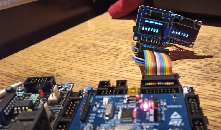
On another note, I looked at current consumptions of various OLED's, and according to this page, a 128x64 0.96” can pull 21mA at max contrast with all pixels lit. As the STM32F4 board docs state, the integrated 3.3V regulator can only supply 100mA max. I wonder if problems some people were having with multiple OLED's might be related to that. So to be on the safe side and to avoid heating the poor little SMD IC, I'm going to add an optional on-board 3.3V regulator or input.
-
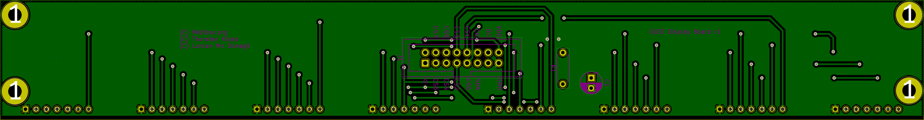
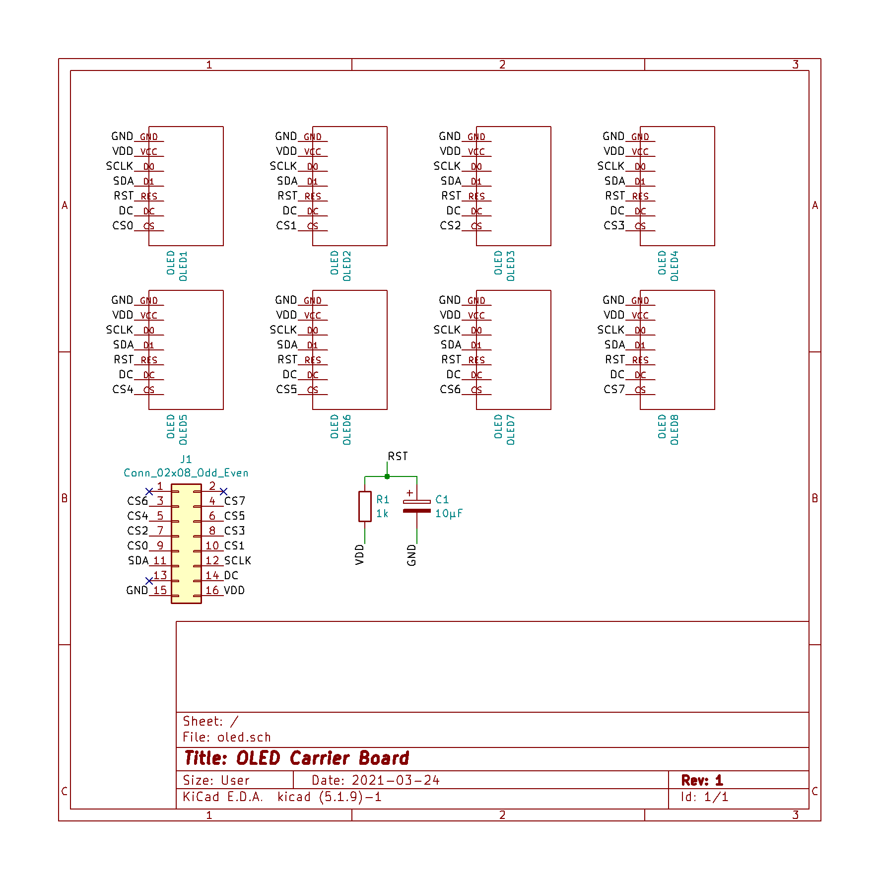
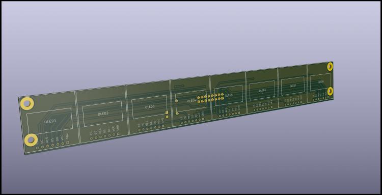
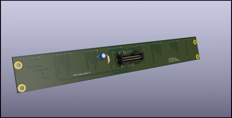
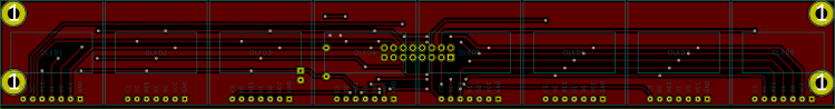
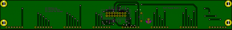
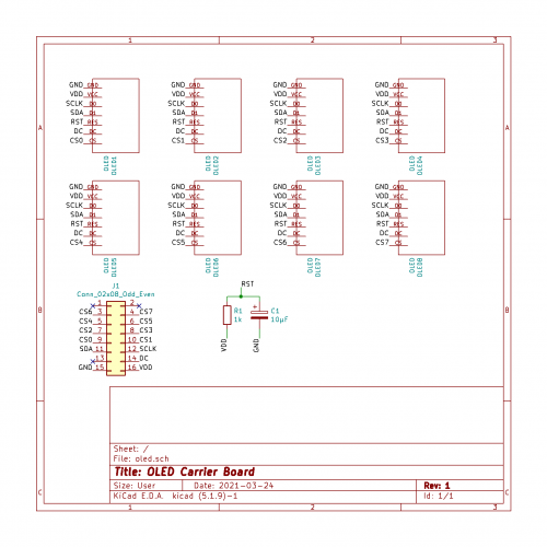
Hi, I'm building a MCU type controller and I'm starting to design some PCB's for the various modules. I'm planning to share them here so other users can use them if they want, if that's ok. The first and simplest one is an 8xOLED carrier board to connect to J15A of the STM32F4 core. Initial tests on a breadboard with 2 screens work fine. It is my first time using Kicad and also designing a 2-layer board, so I'd like to get some feedback before sending them to the fab house. OLED's are 0.96'' SSD1306 4-wire SPI type Mechanically the OLED's are plugged into 1x7 sockets Each 'channel' is exactly 1.1 inch wide. It leaves a little wiggle room between the screens, and should allow the case too be quite compact I remember seeing another schematic with added 100nF decoupling caps, but they're not on Thorsten wiring diagram, so I'm wondering if I should add those NOTE: I'm going to extend the board to avoid having the holes running under the OLED's.
-
"normally" we use here 7 Pin SPI SSD1306 (GND,VCC,D0,D1,RES,DC,CS) connected like this: purple Lines = CS-Lines: the first (8or?) 16 CS/purple lines you get direct from the Core STM32F4, > http://www.ucapps.de/mbhp_core_stm32f4.html the 48 Rest CS-Lines from 595-Dout-Shiftregistors-Pins (6xICs with each 8 Pins) > we call that http://www.ucapps.de/mbhp_dout.html The Update Rate will be a bit slow - but for Label a static Mixer Desk, it will be ok? custom Bitmaps: http://wiki.midibox.org/doku.php?id=how_to_create_custom_glcd_fonts_icons_bars_for_midibox_ng @ Labelitself, I myself have a simular thing, but for a Midi>CV Device, i have to label Encoders... i managed it to save a huge array of "chars" - like this...: char Label[512][8] = { {'3','0','3',' ',' ',' ',' ',' '}, {'6','0','6',' ',' ',' ',' ',' '}, {'7','0','7',' ',' ',' ',' ',' '}, {'8','0','8',' ',' ',' ',' ',' '}, {'9','0','9',' ',' ',' ',' ',' '}, {'-',' ',' ',' ',' ',' ',' ',' '}, {'*',' ',' ',' ',' ',' ',' ',' '}, {'/',' ',' ',' ',' ',' ',' ',' '}, {'+',' ',' ',' ',' ',' ',' ',' '}, {'A','M','P',' ',' ',' ',' ',' '}, {'A','M','P',' ','E','N','V',' '}, {'A','M','P',' ','L','F','O',' '}, {'A','M','P',' ','M','S','Q',' '}, {'A','D','S','R',' ',' ',' ',' '}, ... with all possible Names - that i could use for Control-Voltage Projects.... i save this on SD-Card, on a .sys file (no PC involved the microcontroller do that) - in a Patch aka Song i then Recall it like this: MIOS32_LCD_DeviceSet( 3 ); // select Display 3 MIOS32_LCD_CursorSet(0, 1); // Select Vertical the second Line, Leftmost Horizontal MIOS32_LCD_PrintFormattedString("%c%c%c%c%c%c%c%c", // 8 Chars is max if you use BIG-FONTS Label[ aout[ENC].sel_label] [0], Label[ aout[ENC].sel_label] [1], Label[ aout[ENC].sel_label] [2], Label[ aout[ENC].sel_label] [3], Label[ aout[ENC].sel_label] [4], Label[ aout[ENC].sel_label] [5], Label[ aout[ENC].sel_label] [6], Label[ aout[ENC].sel_label] [7]); where ENC is the Encoder Number where the LCD is situated. aout[].sel_label: i save that Var on SD-Card-with the Patch / and load the Patch via Midiprogramchange. // with a given Number you adress a Name... you can also custom Labels, with ease with 2 additonal Rotary Encoders (while one is the cursor) (and the other one change the Letter), you might need for a UI-for Midibox at least 3 Encoders(with inbuilt pushbuttons) and 1 SSD1306 in order to SAVE and LOAD or ADD Custom Names...
-
Hi Frederik, Yes, most ports with specific functions can be used in parallel. J8/9 is for SRIO i.e. input/output shift registers that chain in parallel (DIN/DOUT) J19 is for SPI with two chip selects (AINSER/AOUT) etc. Check the STM32F4 Core details The SRIO chain extends in series parallel, no need for additional Cores generally. Regards, Andy
-
Hi! I am looking for Core STM32F4 kit + board. Maybe someone has one for sell? Regards, Michał
-
SSl Blog Post 02 Hello again, Last time I wrote about the design process of my console. In this post I want to focus on the electronic part. In the last couple of weeks I searched for the right knobs, faders and pots for the project and I nearly found all I need. The pots were the simplest part. I opted for the Alpha 10k Lin https://www.musikding.de/Alpha-Potentiometer-16mm-10k-lin Each channel will have one motorized fader. Here I choose the PSM01-082A-103B2. https://www.mouser.de/ProductDetail/bourns/psm01-082a-103b2/?qs=MAZTpT1IVl8rvdecO07rRA==&countrycode=DE¤cycode=EUR 14,76€ when I buy more than 25 is a good deal I think. The ones from alps are very pretty, but with prices over 30€ per piece they are quite expensive especially because I need 33. For the bus channels I opted for simple 60mm faders. Also 10k lin, not very investing. https://www.reichelt.de/schiebepotentiometer-stereo-10-kohm-linear-rs60n12-lin10k-p73870.html?&trstct=pol_1&nbc=1 The knobs where a little harder to find. For the Solo Cut and Rec knobs I want to have knobs with Leds which I can connect to an DOUT module separately. So I could press Solo on the console but deactivate it inside my DAW and the LED would follow my actions. After quite a bit of searching and some phone calls with distributors I finally found these. https://de.farnell.com/nidec-copal-electronics/cfpb-1cc-4w9/drucktaster-spst-0-005a-5vdc-panel/dp/3498758 The knobs inside the channel strip are still to be found. The need to be snapaction knobs with a white cap with the measurements of 5mm per side. I couldn’t finde the right ones even after quite some hours of searching. Maybe I’m just searching without the right search terms? Maybe someone of you knows the answer to that problem I didn’t start the search for LEDs just yet. I think and hope these should be easy to find. For the modules I chose STM32F4 for the cores, AINSER 64 for the pots and faders, NG MF for the motorfaders, DIN for the knobs and DOUT for the LEDs. I especially need quite a lot of AINSER modules and I’m still figuring out a way to connect more than two to an STM32F4. I found some blogposts but could get the answer out of these. They suggested it should be even possible to connect more than three? I obviously want to use as less cores as possible. This build will be huge either way. I can connect the MF modules directly to a pc without a pc. Thats what is written on the website. But how do I connect these to the pc? Via midi? There is no USB port on these modules right? And I also should cascade them. I need 5 modules. I want to use 33 motorized faders and that’s quite unfortunate because every mf module only supports 8. How do I cascade these modules? Also via MIDI? The last problem I ran into is the meter bridge. This could be a whole blogpost of its own… My plan was, or partly still is to use 10 7“ displays connected to a 10 times HDMI splitter, which tells the PC there is only one REALLY big screen. But after buying quite some displays to test out I figured out 90% of the screens for sale online are totally crap! Ok, I searched for quite cheep ones, but I need 10 of them and if I had unlimited money I would buy the original ORIGIN console… But I don’t have access to unlimited amounts of cash so I need a cheap display which works. The first one I ordered was the perfect size and easy to operate. But I only could see the image looking from one specific angle. Moving my head just a little bit the whole display would turn blue. The second one was advertised to be 7“, but the one that were delivered to my was only 3,5“…are you kidding me? Out of anger I searched for analog VU meters. I really like the looks of these and figured out these work with voltage. Is it possible to drive VU meters with a midibox module? Maybe with an AOUT module? So many more questions but I already wrote a whole book here…sorry for that. If you still reading in this point thank you very much! Have a nice day! Frederik
-
https://github.com/midibox/mios32/blob/master/mios32/STM32F4xx/mios32_ain.c https://github.com/midibox/mios32/blob/master/modules/ainser/ainser.c https://github.com/midibox/mios32/tree/master/modules/aout Basic drivers/assignments: https://github.com/midibox/mios32/blob/master/mios32/STM32F4xx/mios32_spi.c https://github.com/midibox/mios32/blob/master/mios32/STM32F4xx/mios32_iic.c Maybe it would be easier for you to use the Arduino and output an analogue voltage to be read by the STM32F4 AIN? That way you can use your working system without much extra coding effort. MBIO supports AIN either on the MCU ports J5A/B or using the AINSER module (typically less noise on the signal).
-
As far as I know, there are no I2C peripherals that were coded into MIOS32. The closest thing that I am familiar with is the I2C MIDI modules, that according to TK. were not trivial to code for, and at that on very low-performance 16F PIC chips. All the MBHP framework gives you is a hardware port on the MCU. You could consider to compare your arduino sketch with a device running off an STM32F4 chip or similar. Alternatively, you might find more code examples of SPI devices. Maybe you can try to code a driver for a similar sensor with an SPI interface? The uCapps project is here: http://ucapps.de/midio128.html -- it is more targeted towards general users who would like to use the project without writing code for it. The git project is here: https://github.com/midibox/mios32/tree/master/apps/controllers/midio128_v3 You would need to modify the code to suit your needs. Note that the code is written in C, not python. You can find the documented functions and some examples here: http://www.midibox.org/mios32/manual http://ucapps.de/mios32_c.html Best of luck to you if you decide to follow this journey. Others will probably not write the software for you, but if you post your modifications and explain where you are having difficulty, some might be able to help.
-
I plan to use alpha pots. I got them recommended from a friend. Hopefully they will do a good job. I found an article in another thread which referred to the possibility to use 3 cores or even more. I found some background information about using 3 cores with an stm32f4 but not more. There should be a limit to the core processing wise but unit now I couldn't find the numbers. Thats an interesting idea with the minicomputers. I have to look into that! Thank you very much so far :)
-
i do managed to get a a workflow with kicad to get PCB assembled by JLCPCB... all parts are reffered to the jlcsc too... so after a while of different prototypes i have a good database of SOICs 0805 1208 sized parts that are used for different modules or Userinterfaces, also some common Buttons, and SSD1306ers... Dipcore, and i also have STM32F4 Discovery Footprint - but that one have to be repaired first... mostly you whould choose waveshare anyway (which i dont have, i use dipcore since i have small project at the moment) but the the 3D Folder and the Footprintfolder is full of not used files, which would blow up a database for others, and that is not a good starting point, so some kind of "sammle alles und speicher woanders ab" "collect and save too" script would be nice, as i said, if you can deliver me such thing, i am the last that want to hide my work...