Search the Community
Showing results for 'STM32F4'.
-
Just want to share, that the new Behringer RD-8 drummachine is using a STM32F405. Maybe MIOS is an option as an alternative Firmware for those of you who own one.
-
Hi all, After having previously built an MB-6582, I thought I'd have a go at building a midibox FM. Following TK's build guide on ucapps, I've built the OPL3, DIN, DOUT, and CORE modules using PCBs ordered from Modular Addict. For the core, I thought it would be fine to use the newer STM32F4 module because it is mentioned as a more modern alternative to the PIC-based one. However, only after finding out more about it (my mistake), I'm now unsure if that was the right choice. I don't want to try to replicate Sauraen's 2.1 version because it looks far too ambitious for me and I need to rely on something fairly well documented and straightforward. My coding skills are very basic, and I just want to use the control surface of TK's 1.4 version. Is it possible to build the 1.4 version using the STM32F4 without writing or changing a lot of code myself? Or would I be better off using an LPC17 or a PIC-based core instead? I already have some spare PIC18F4685s, but I suppose if I use an LPC17 then I won't have to add a midi IO module later. Is that correct? I appreciate any advice. :-) Cheers, Theo
-
If anybody wants to sell me their STM32F4 Core board please contact me. I am located in Germany... Thanks, Emre
-
Hei I have some SPI problems here... A AINSER slows down the SD-Card Access - so the programm is not usable anymore. I already optimized the Ainser-Side (see below), but that is not enough, I dont know if it is the prescaler Factor, that also changes SD-Card in a way (since booth are SPI...) I save a lot off informations on the SD-Card, so each percent off performance makes seconds off less waiting time. Is there something like a prescaler that can be set for the SD-Card?= How give the SD-Card more priority? I know how to give prioritys for RTOS Task that i created, but i dont know how to do that with SD-Card (on rootlevel) thx for any info! I have 2 AINSER8 moduels connected to a STM32F4(disconver), not multiplexed - i have 16 faders connected directly to them. as soon i scan the AINSER: static void TASK_AINSER_Scan(void *pvParameters){ // This task scans AINSER pins and checks for updates portTickType xLastExecutionTime; xLastExecutionTime = xTaskGetTickCount(); while( 1 ) { vTaskDelayUntil(&xLastExecutionTime, 10 / portTICK_RATE_MS); // 202 orginally 1ms // scan pins AINSER_Handler(APP_AINSER_NotifyChange); } } The Write or Read on the SD-Card goes up from 1seconds to 14seconds (in my case) so i copied the ainser.c to my project, and made some edits, the most significant emprovement was to change the prescaler from 64 to 8: // init SPI port for fast frequency access MIOS32_SPI_TransferModeInit(2, MIOS32_SPI_MODE_CLK0_PHASE0, MIOS32_SPI_PRESCALER_8); // Initialisierung des SPI-Ports i also tryd other values, but on some values the Ainser didnt react at all, or i got random values. When i remove this Prescaler LINE, the AINSER gives no output to my code, what makes me a bit wondering since in MIOS-FUNCTIONS there is statet: So my expirience - the Prescale may not have a effect on SPI2, but on SPI0 (where my SD-Card is connected). I also changed to get this Prescaler8 working, The driver from MIOS32_SPI_PIN_DRIVER_STRONG to MIOS32_SPI_PIN_DRIVER_WEAK (which is i know not recommented): // pins in push-poll mode (3.3V output voltage) MIOS32_SPI_IO_Init(2, MIOS32_SPI_PIN_DRIVER_WEAK); // 2: Ainser_SPI - J19 i then tryed to remove the Multiplexer Code, and fixed the modules to a count off 2, At the end i have 4 seconds Access Time to my SD Card which was without AINSerial 1second And without my modifications 14 seconds I already set the priority off Tasks like this: // TASK - PRIORITYS #define PRIORITY_TASK_SEQ ( tskIDLE_PRIORITY + 5 ) // higher priority than MIDI receive task! #define PRIORITY_SD ( tskIDLE_PRIORITY + 3 ) #define PRIORITY_LOPRIO ( tskIDLE_PRIORITY + 2 ) #define PRIORITY_LCD ( tskIDLE_PRIORITY + 0 ) // idle #define PRIORITY_PAD ( tskIDLE_PRIORITY + 0 ) // idle #define PRIORITY_TASK_AINSER_SCAN ( tskIDLE_PRIORITY + 0 ) // orginal this was 3 So the SD-Task (where i write things on the SD-Card with mutexes and stuff...) is already High priority > off course the SEQuencer is higher... the whole Ainser.c code then looked like this: #include <mios32.h> #include "ainser.h" #include <string.h> ///////////////////////////////////////////////////////////////////////////// // Local variables ///////////////////////////////////////////////////////////////////////////// static u8 ainser_enable_mask; static u8 ainser_muxed_mask; static u16 ain_pin_values[16]; //2 Modules 8 pins static u16 previous_ain_pin_value; const u8 pin_lookup[8] = {7,6,5,4,3,2,1,0}; ///////////////////////////////////////////////////////////////////////////// // Local Prototypes ///////////////////////////////////////////////////////////////////////////// static s32 AINSER_SetCs(u8 module, u8 value); ///////////////////////////////////////////////////////////////////////////// //! Initializes AINSER driver //! Should be called from Init() during startup ///////////////////////////////////////////////////////////////////////////// s32 AINSER_Init(u32 mode){ // pins in push-poll mode (3.3V output voltage) MIOS32_SPI_IO_Init(2, MIOS32_SPI_PIN_DRIVER_WEAK); // 2: Ainser_SPI - J19 // orginal this was MIOS32_SPI_PIN_DRIVER_STRONG MIOS32_SPI_PIN_DRIVER_WEAK // ensure that CS is deactivated AINSER_SetCs(0, 1); // CS für Module 0 AINSER_SetCs(1, 1); // CS für Module 1 // Dont use Muxes ainser_muxed_mask &= ~3; // Sets the enable mask for modules which should be scanned ainser_enable_mask |= 3; // clear all values memset(ain_pin_values, 0, sizeof(ain_pin_values)); previous_ain_pin_value = 0; return 0; } ///////////////////////////////////////////////////////////////////////////// //! This function should be periodically called to scan AIN pin changes. //! A scan of a single multiplexer selection takes ca. 50 uS on a LPC1769 with MIOS32_SPI_PRESCALER_8 ///////////////////////////////////////////////////////////////////////////// s32 AINSER_Handler(void (*_callback)(u32 module, u32 pin, u32 value)) { static u8 first_scan_done = 0; // Variable zur Verfolgung des ersten Scans // init SPI port for fast frequency access MIOS32_SPI_TransferModeInit(2, MIOS32_SPI_MODE_CLK0_PHASE0, MIOS32_SPI_PRESCALER_8); // Initialisierung des SPI-Ports // loop over connected modules int module; int chn; for (module=0; module<2; ++module){ // Schleife über die angeschlossenen Module for (chn = 0; chn < 8; ++chn) { // Schleife über die Kanäle AINSER_SetCs(module, 0); // Setzen des Chip-Select-Pins auf LOW MIOS32_SPI_TransferByte(2, 0x06 | (chn >> 2)); u8 b1 = MIOS32_SPI_TransferByte(2, chn << 6); // Übertragung der Datenbytes über SPI u8 b2 = MIOS32_SPI_TransferByte(2, 0); AINSER_SetCs(module, 1); // Setzen des Chip-Select-Pins auf HIGH u8 pin = pin_lookup[chn]; // Berechnung des Pin-Index u16 value = (b2 | (b1 << 8)) & 0xFFF; // Kombination der Datenbytes zu einem Wert previous_ain_pin_value = ain_pin_values[module * 8 + pin]; // Speichern des vorherigen Pin-Werts int diff = value - previous_ain_pin_value; // Berechnung der Differenz zum vorherigen Wert int abs_diff = (diff > 0) ? diff : -diff; // Berechnung des absoluten Werts der Differenz // Überprüfung, ob der Pin-Wert sich ausreichend geändert hat if (!first_scan_done || abs_diff > 31) { ain_pin_values[module * 8 + pin] = value; // Speichern des neuen Pin-Werts if (first_scan_done && _callback && pin < 8) _callback(module, pin, value); // Aufruf der Callback-Funktion } } } if (first_scan_done == 0) first_scan_done = 1; // Setzen der Flag, dass der erste Scan abgeschlossen ist return 0; } ///////////////////////////////////////////////////////////////////////////// // Internal function to set CS line depending on module ///////////////////////////////////////////////////////////////////////////// static s32 AINSER_SetCs(u8 module, u8 value){ switch( module ){ case 0: return MIOS32_SPI_RC_PinSet(2, 0, value); // spi, rc_pin, pin_value // 2: SPI - J19 case 1: return MIOS32_SPI_RC_PinSet(2, 1, value); // spi, rc_pin, pin_value // 2: SPI - J19 } return -1; } i use to write to SD-card directly with File.c, like this: // Speicherung der Daten auf der SD-Karte MUTEX_SDCARD_TAKE; FILE_WriteOpen ("0.p4", 8); FILE_WriteBuffer(buffer2, sizeof(buffer2)); FILE_WriteClose(); MUTEX_SDCARD_GIVE;
-
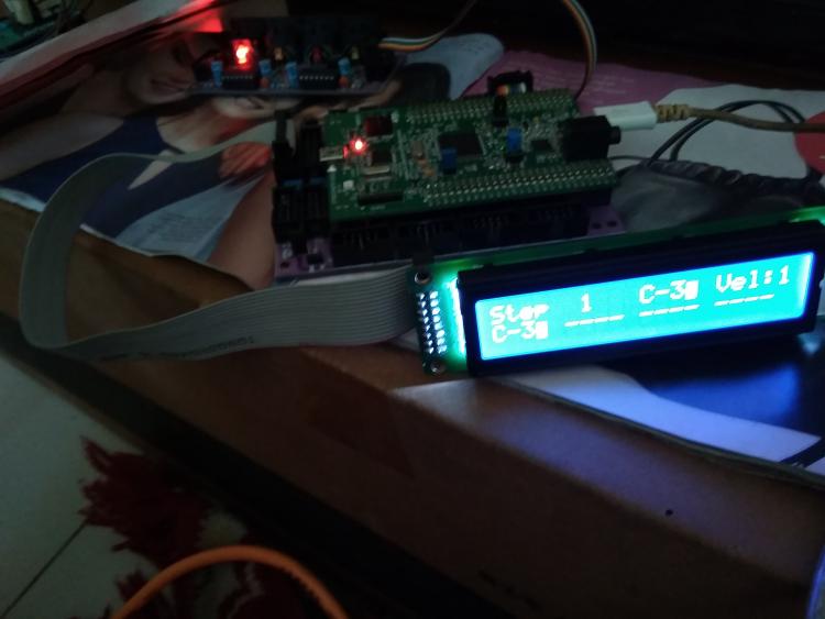
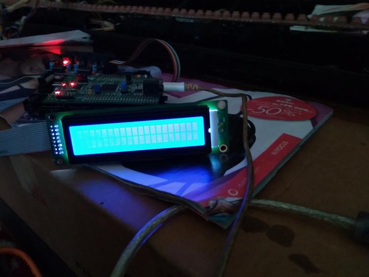
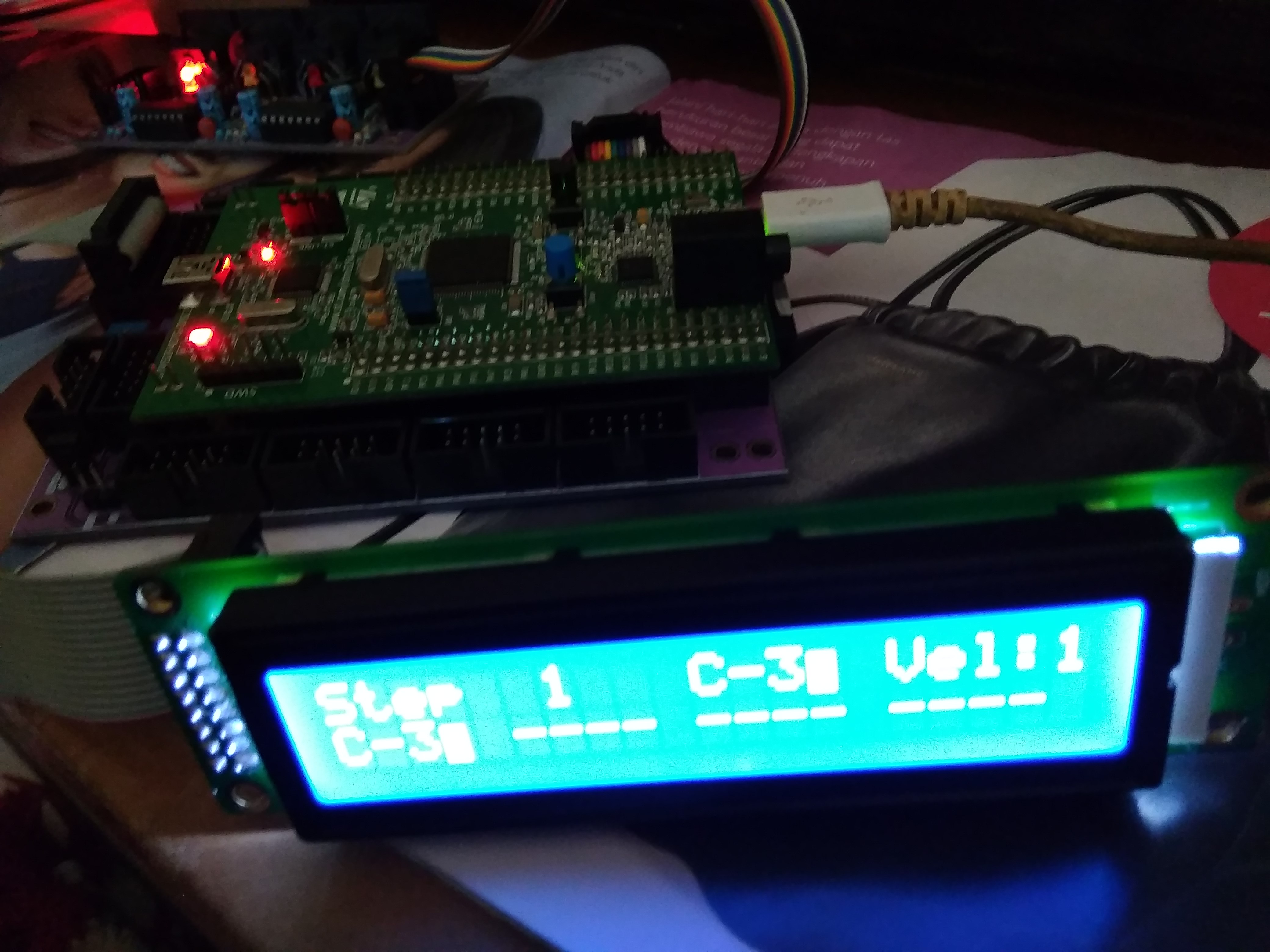
i have built the stibl stc32f4disc midibox correctly and after upload mios studio hex program also seq v4 already appear on my lcd 2x20 with brand not hd447780 (hitachi) but i try to insert mb ng through mios not show in my lcd i please give in suggestion , whether the lcd does not match the driver in mb ng or there is a system that must be in input as shown in my picture

-
Hi all, I received my STM32F4 board in anticipation of building my SeqV4. I flashed the bootloader with ST-LINK on Win7 x64, and then used MIOS Studio to upload the SeqV4 application. From there, MIOS Studio doesn't want to talk to my STM32F4 anymore -- it sees 4 Midi ins and 4 Midi outs from the Seq, but no combination of those four ports will let me talk to it -- it says 'no response from device' or something similar. The bootloader fail-safe mode works (holding the USER button down on reset keeps it in the bootloader). But I can't communicate to it while it's actually running the Seq app. I think this is because of the known Win7x64 USB MIDI driver issues. But I find " The GM5 driver is currently not supported for the MBHP_CORE_STM32F4 module, but it's planned to provide it in future!" on the MIOS32 download page... so this driver won't help in this situation? I'd like to keep the four USB Midi In/Outs because I'll be using this thing with Linux mostly, but I can't get MIOS_Studio working on my Arch Linux install at the moment. The pre-compiled version didn't work, and compiling it from source caused me some GTK errors that I haven't sussed out. I'd also like to be able to update the Seq App in the future without having to disassemble my device to get to the button... Any help? I'll probably continue debugging the MIOS_Studio app on Linux to avoid Windows as much as possible, but I thought I'd ask here if there were any suggestions.
-
Hello all! I've run into a problem while implementing a granular synth on a STM32F4 Discovery using MIOS32. The synth algorithm makes use of floating point operations - I thought it would not be a source of performance issue, since the MCU has a dedicated unit for floating point calculations. Actually, there are performance issues, because the FPU is not enabled for the compiler (I'm using the original toolchain). There's a line commented out in trunk/include/makefile/common.mk: ifeq ($(FAMILY),STM32F4xx) # leads to a crash - reason not analysed yet #CFLAGS += -mcpu=cortex-m4 -mfpu=fpv4-sp-d16 -mthumb -mfloat-abi=hard -mlittle-endian -ffunction-sections -fdata-sections -fomit-frame-pointer # works (but FPU not enabled) CFLAGS += -mcpu=cortex-m4 -mlittle-endian -ffunction-sections -fdata-sections -fomit-frame-pointer endif I tried to uncomment that line, it compiled, but crashed for real on the MCU. Do you know if there's a workaround for that? What can be the source of this problem? Rewriting the synth algorithm is not an option, this is my thesis project, and the deadline is close. Thanks in advance!
-
Hello, This is an introduction for my new baby, a really funny toy, the HAARP (yes I like conspiracy theory ;) It's a pure MIDIbox Project, just a dedicated CS and some coding. It works with any STM32F4 Core. Why? Many synths have an integrated arpeggiator, the SH-101 is well known for that, but the available parameters are still limited. There is also some good plug-in I think especially of the Ableton live's one but it's software. So I designed an hardware one, "LIVE" oriented, starting from the @TK.'s arp example. No encoder(except for MENU section Data entry), all parameters are directly accessible and are potentiometers. The screen is a small color TFT with a resolution of 128x160(sorry for picture, colors are better in real). It's 8 independent voices. 8 banks of 8 Presets. Session are saved/loaded from the SD Card. The Arpeggio parameters are divided in 3 sections: First is the TIMING Section (Purple pots): On/Off button, HOLD Button, it holds or releases the Notes in the notestack. The MODE Pot, it's UP, DOWN, UP-DOWN and AS-PLAYED, fr the moment but I will implement more. The RATE, from slowest to fastest, from 4 Bar to 32nd with dotted and Triplet value. The RESYNC, it retriggers the arpeggio, values are the same as RATE parameter. The OFFSET, it will shift left or right the starting step(note). Is Note Stack and MODE dependent. The DELAY, it will delay the whole arpeggio within the step range(duration), is RATE dependent. The GATE, the length of the Note, max is STEP length, is RATE dependent. The SHUFFLE, it will delay all the odd steps, in the range of an half step, is RATE dependent. Second is the TRANSPOSITION Section (Yellow, Orange, Red): Simple Transposition On/Off (Yellow). Simple OCTave Transposition, +/- 10. Simple SEMItone Transposition, +/-12 Repeat On/Off. Repeat, LOOPS number, 1 to 8. Repeat, SHIFTing on each loop, +/-32 semitones. Force to Scale On/Off Force To Scale, SCALE, list is the same as the Force to Scale example from the repo. Force To Scale, ROOT from C to B semitone. Third is the VELOCITY Section. REGEN Pre/Post(Target process) button. REGEN, +/- 100% Target process On/Off. TIME, the time to reach the target value, in PRE initial value is the regenerated value. in POST initial value is the one stored in the Note Stack. TARGET is the targetted value, 0 to 127. RETRIG, if on the TIME is retriggered by the RESYNC parameter. The main page of the screen represents an octave range, the note color changes depending on the octave, there's a Velocity section on the bottom, it's like a piano-roll. In the code, the arpeggio processing is ready, it remains me to complete the MENU section, I was waiting for the CS PCB to write it, now I can... ;) This little guy is to much fun, so I can't keep it for me. Then i will propose it to you ASAP. and I hope it will help me to finance some other bigger projects I've got in my back-pocket ;) I will try to make it available in two format, I'm currently working on a PCB for USB host/device, sdCard MIDI etc.. which will fit for both version and will be reuse for other small toys like that. An Eurorack version for the patching addicts. I used a MCP3204(4 channels) instead of a MCP3208(8 channels) for the AINSER, it's an AINSER32. I use only 2 channels for the 16 pots(8Multiplexed lines * 2 channels), it remains 16 analog Inputs which are accessible to connect some CV In Modules, thanks to @Hawkeye for making me think about this. The SRIO Chain is available too, you can connect GATE In (DIN) easily. You will be able to connect the MIDIPHY CV/GATE Out Modules which will be available soon. @latigid on is working on it. MCAN will be available, for an internal MIDI bus within your Eurorack, I reuse the BUS1 and 2 from the Euro Power connector for that purpose. A Desktop version, for MIDI purpose only(except if i find a way to add some CV/Gate without designing a too much big box). Voilà! More information will be available soon. For the moment this is a small video I made, I seem a little febrile but it's because I continue to discover it every day. I really love this little toy, it is very effective and musical, even in LIVE and if the Force To Scale is activated, there's no wrong note ;) Best regards Bruno
-
Found some, thx!
-
Hello where do we connect the CS1 and CS2 of a GLCD 128x64 to the STM32F4 core. This is the way I think should be connected: GLCD STM32F4 1(CS1) ? 2(CS2) ? 3(VSS) VS(J15A) + 10K Pot 4(Vdd) VD(J15A) 5(Vo) 10K Pot 6(D/I) ? R/S(J15A) 7(R/W) RW(J15A) 8(E) E(J15A) 9(DB0) D0(J15A) 10(DB1) D1(J15A) 11(DB2) D2(J15A) 12(DB3) D3(J15A) 13(DB4) D4(J15A) 14(DB5) D5(J15A) 15(DB6) D6(J15A) 16(DB7) D7(J15A) 17(RST) ? 18(VEE) 10K Pot 19(A) B+(J15A) 20(K) B-(J15A) Attached the specifications of the GLCD I searched for this all over the site but I didn’t find anything about it. Have I missed something? Thank you WDG0151.pdf
-
Hi all For info I just check STM32F4disco at one of my regular component supplier, and there is a new one coming soon. So I check at manufacturer and the board is now NRND, replaced by something looking absolutely the same but with STM32F407VG in place of STM32F407VE. http://www.st.com/web/catalog/tools/FM116/SC959/SS1532/PF252419 I have no knowledge for understanding/comparison about change. Just to let you know there is certainly a need to check what's going on, and be sure MIOS/MBHP will run fine with new STM32F4 board Best Zam
-
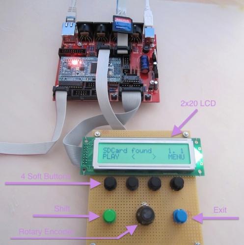
 Christmas time is time to get some serious projects started! Hi, my name is Roberto this is one of my bigger DiY project and my first post here. first of all, this is a very cool platform, well documented and really expandable. what i was looking for! I bought a MBHP CORE STM32F4 and some modules like DIO, DOUT, AINSER64, MIDI IO and AOUT_NG. My goal is to build a midi controller to interact with an attached computer and software via usb midi. later i want to extend it to work with midi and control voltage outputs for synths/modular application. I have basic knowledge in electronics, decent soldering and some beginner programming skills. so more or less I’m a NOOB. I soldered all the boards except MIDI IO and AOUT_NG and made some tests and detected that i have PROBLEMS WITH THE INPUTS. Although i am able to send midi notes to the DOUT and light LED’s, I’m not able to get any inputs from the DIN (with buttons) nor AINSER64 (with faders). So, i’m stuck here right now and have some questions about it: The SD-Card Holder (and the SD Card) is missing on the MBHP Core, because i still wait for it to be delivered. Is it crucial to have it soldered? And, i didn’t planed to attach a LCD. Is it needed to make the whole thing work? here is what i did until now: checked for shorts checket IC, caps and cable polarity installed bootloader and firmware: https://www.dropbox.com/s/mg1oudmpp6ekajq/bootloader_firmware.png?dl=0 installed MIOS : https://www.dropbox.com/s/fo84lnr3t7h8610/mios.png?dl=0 installed MIDIO 128 V3 : https://www.dropbox.com/s/yhp1phjezwotdgx/midiio128.png?dl=0 checked DOUT with a RGB LED: https://www.dropbox.com/s/5txs634ny5yjple/RGBLED.mov?dl=0 checked DIN : https://www.dropbox.com/s/3p5clopkz8eivwl/DIN.jpg?dl=0 The button is attached to J3 (VS - D0) of a DIN module. I can’t see any incoming messages in MIOS Studio… Can i measure the functionality with a multimeter? All i see is a drop from 4.8v to 0v at pin 11 of IC1. But i guess it’s not possible to use a multimeter to measure the serial output… The same with AINSER64, Pot attached to VS - VD on the sides and A0 on the middle, no messages on the MIOS Studio terminal… The green LINK LED stays lit on the AINSER64, so i guess some communication is missed somewhere. I searched for solutions all over the site and i didn’t find any satisfying answer. did i miss something? all the best and cherry friskmas roberto
 -
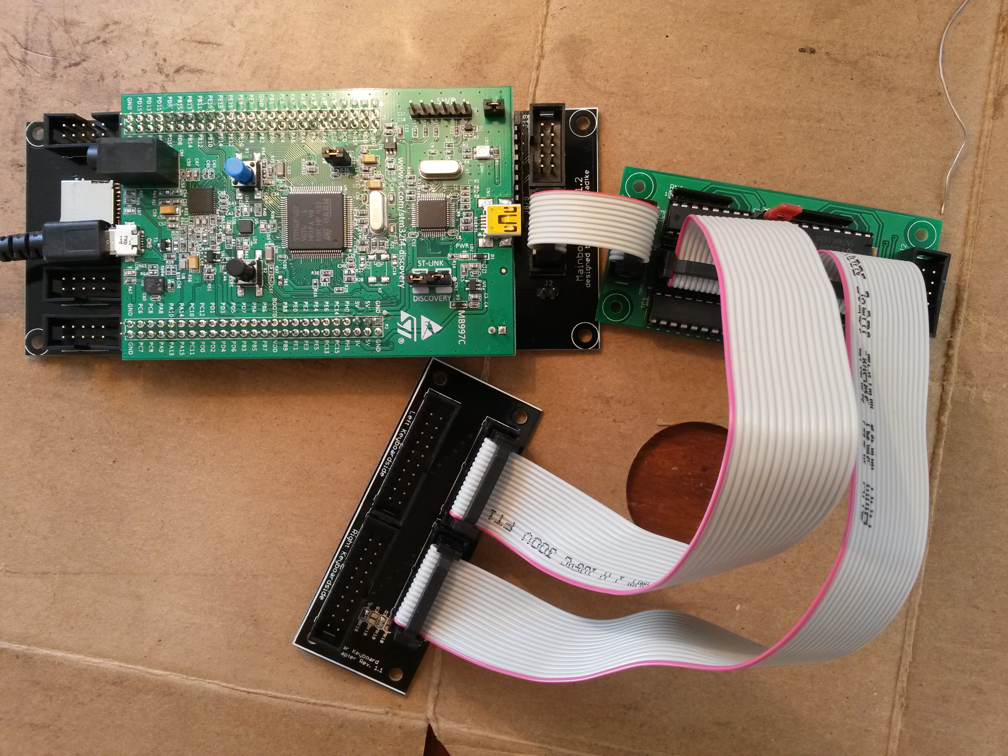
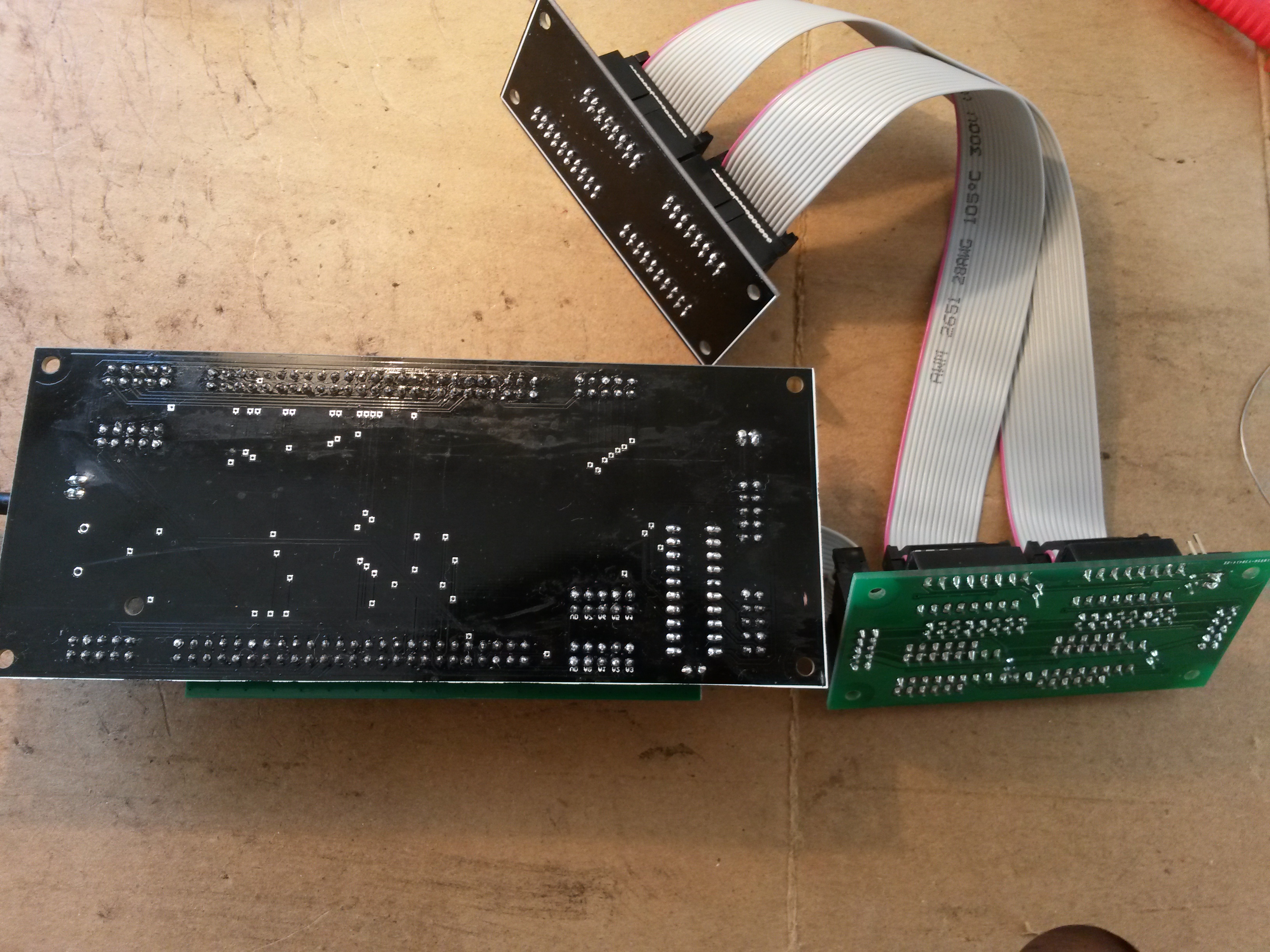
 Hello all, I've build my core stm32F4(fantomxr pcb) + diomatrix + fatar adapter to connect my 88 keyboard. I installed midibox kb and connected everything, but i can't output any midi, so i guess i did something wrong :) I tried the virtual keyboard and i didn't receive any midi input in my daw, so i was wondering if my setup was correct, it seems midibox kb is loaded correctly(cf picture). Here's the setup of my midibox kb: [13020.190] kb 1 debug on [13020.190] kb 1 midi_ports 0x0001 [13020.190] kb 1 midi_chn 1 [13020.190] kb 1 note_offset 21 [13020.190] kb 1 rows 12 [13020.191] kb 1 velocity on [13020.191] kb 1 release_velocity off [13020.191] kb 1 optimized on [13020.191] kb 1 dout_sr1 1 [13020.191] kb 1 dout_sr2 2 [13020.192] kb 1 din_sr1 1 [13020.192] kb 1 din_sr2 2 [13020.192] kb 1 din_key_offset 40 [13020.192] kb 1 din_inverted off [13020.193] kb 1 break_inverted off [13020.193] kb 1 make_debounced off [13020.193] kb 1 break_is_make off [13020.193] kb 1 delay_fastest 50 [13020.194] kb 1 delay_fastest_black_keys 0 [13020.194] kb 1 delay_fastest_release 150 [13020.195] kb 1 delay_fastest_release_black_keys 0 [13020.195] kb 1 delay_slowest 1000 [13020.195] kb 1 delay_slowest_release 1000 [13020.196] kb 1 ain_pitchwheel off [13020.196] kb 1 ctrl_pitchwheel 128 (PitchBend) [13020.196] kb 1 ain_pitchwheel_inverted off [13020.196] kb 1 ain_modwheel off [13020.198] kb 1 ctrl_modwheel 1 (CC) [13020.198] kb 1 ain_modwheel_inverted off [13020.198] kb 1 ain_expression off [13020.198] kb 1 ctrl_expression 11 (CC) [13020.199] kb 1 ain_expression_inverted off [13020.199] kb 1 ain_sustain off [13020.199] kb 1 ctrl_sustain 64 (CC) [13020.205] kb 1 ain_sustain_inverted off [13020.205] kb 1 ain_sustain_switch off [13020.205] kb 1 ain_bandwidth_ms 0 [13020.205] AIN Calibration Mode disabled. Then i wanted to check if my diomatrix was ok so i connected I1 to O1 on J3 to check for midi input, but i did not receive anything(no data in mios input). Is there a way to troubleshoot easily diomatrix ? or some tension to check on the core stm32F4 , i've checked my soldering and connection with a multimeter and everything seems ok. Thanks!
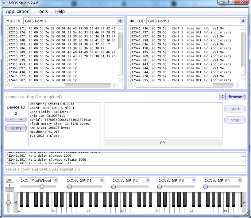

-
I finished my build today, turned on my SeqV4.... some LEDs lit up, and there are solid top rows (black bar) on the LCD displays. There is a red LED flashing on the STM32F4. What's going on? I built my core and tested the discovery board months ago with LCDs attached. Successfully set up, read SD card, screens displayed as expected. I haven't turned on the core since then as I've been focused on enclosures and other aspects of the build. Now today, I assemble the enclosure with my CS board, two MIDI I/O, one Quad IIc, and one Line Tx. I removed the USB Power jumper and connected this 5V DC/DC converter that was recommended to me by another SeqV4 builder https://www.adafruit.com/product/1385 The AC adapter I used was 7.5V/2A. When I turned it on, I got the results described at the top of this post. I powered off, disassembled, and tested the output of the converter which measured 5.27V. Next, I replaced the USB Power jumper, disconnected all peripherals except the LCDs, and powered up using the USB port. Same result, core won't boot. Could the 5.27V supply have damaged the discovery board? Do these symptoms sound indicative of some other failure or user error? Thanks so much for any help!
-
I have some midibox kits lying aroud, but no plans.. It is: a fresh STM32F4 core a core kit from Smash TV plus the pcb with all parts two midio part kits, also with pcbs They are here in .NL. Asking price is €125 including shipping in EU. Or shoot me an decent offer if you wish..
-
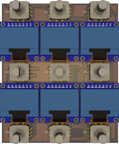
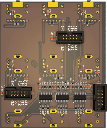
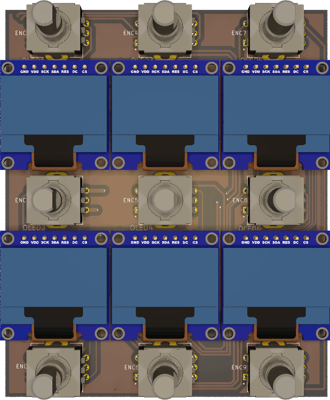
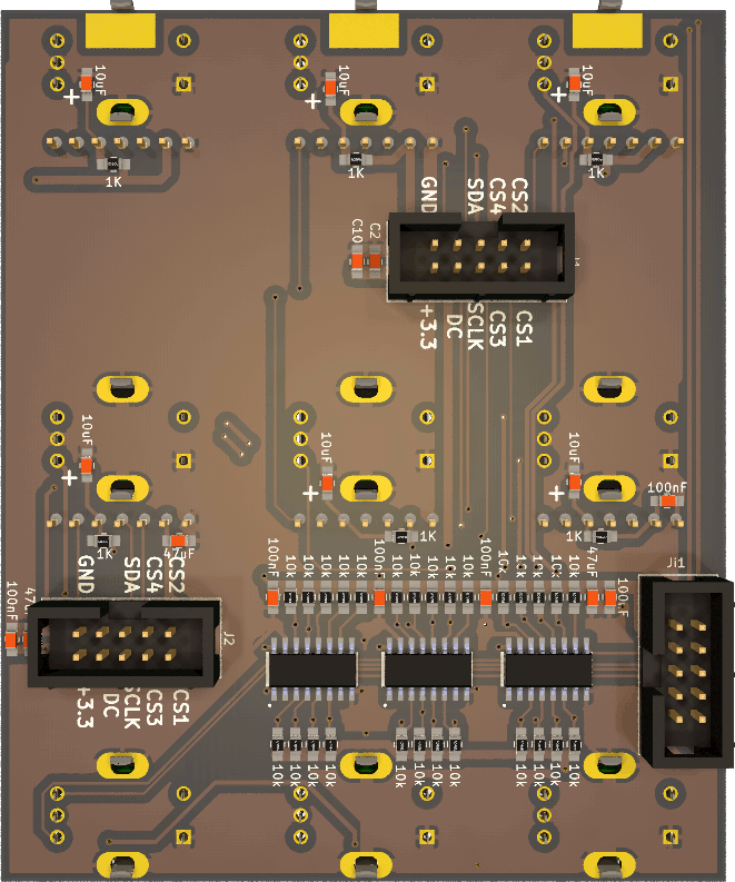
Lets get started... Goal is a midicontroller for Ableton live, at the beginning as simple midicontroller, maybe later to transfair Labels via max4Live to the controller... it will not a midibox-ng script, it will be a own program based on the MIOS-platform. Hardware first, i designed a 6xSSD1306 + 9 Encoder Board, that is scaleable --- i will use 8-10 off it, its documented here (incl gerbers): http://wiki.midibox.org/daw-encoder-display i already have the Motorfaders and the ready soldered and flashed mf-ng boards, i will controll them with a stm32F4 board... which also handles the encoders and displays. in order to drive the displays stable, i use latigid-ons display driver board. - this is also the offical discuss topic for this project (which is linked in the wiki)
-
hi i cant find in the documentation/remember/no-search-results: which pin on the discovery board i have to solder a cable and a switch, to get into boatloader mode with a switch from the outside of without opening the midibox... thx for help
-
ich hätte da noch eine andere Frage . Bisher habe ich mit einem LPC Core gearbeitet. Es soll aber demnächst auch ein STM32F4 Core her . Muss ich die Toolchain um die apps zu compilen dann jedesmal umstellen . e.g export MIOS32_FAMILY=LPC17xx export MIOS32_PROCESSOR=LPC1769 export MIOS32_BOARD=MBHP_CORE_LPC17 .. export MIOS32_FAMILY=STM32F4xx export MIOS32_PROCESSOR=STM32F407VG export MIOS32_BOARD=MBHP_CORE_STM32F4 oder kann ich 2 Toolchain profile haben (mit verschiedenen Pfaden ) ? lg , jascha
-
Hi All, I've got an stm32F4 and a speakjet chip knocking around, so I thought I'd try out the speakjet synth for mios32 in mios32\trunk\apps\synthesizers\midibox_sj_v2. . Unfortunately, the schematic in the svn repo for the app. is for the lpc core module, looking at the schematic compared to the lpc module pinout, if I've got this right, the speakjet chip connects d2,m0,m1,rst to J10.d3, .d2, d1 and .d0 and the speakjet rcx pin connects to J5b.A7, will the midibox_sj2_v2 app. work if I connect the respective pins as they're laid out on an stm32F4 (pe8,9,10,11 for the J10 pins and pb1 for the j5b.a7-rcx connection)?
-
I'm building an NG as a central controller for several synths, so that I'll be able to control parameters for a bunch of synths using one NG interface. Right now I'm thinking the controller will have two 4x20 LCD displays, with 16 or 32 encoders, and about 40 buttons. Is there any real advantage to basing a MIDIbox NG controller on a STM32F4 core? Or could I use an LPC17 core without any real difference in performance?
-
Hey all, I finally got a Discovery board and managed to get the MIOS bootloader installed on it, but when I flipped the board around after connecting PA9 to the 5V pin, nothing. The computer won't even recognize that anything is plugged in. Is there anything I can do to fix this? I'm running Windows 7 64 if that makes any difference.
-
Alright, now I see the problem - the notation for the "Connections to Pins on STM32F4 DiscBoard" has been added by yourself, and I agree, that the data input of the SD Card has to be connected to the serial data output of STM32F4, and vice versa. Compare with the MBHP_CORE_STM32F4 schematic: http://www.ucapps.de/mbhp/mbhp_core_stm32f4.pdf SDCard J1 DI -> MBHP_CORE_STM32F4 J16 SO (-> PA7) SDCard J1 DO -> MBHP_CORE_STM32F4 J16 SI (-> PA6) Problem solved :) Best Regards, Thorsten.
-

STM32F4 SDCARD Reading CID failed with status -256! Solved
gerald.wert posted a topic in MIDIbox SEQ
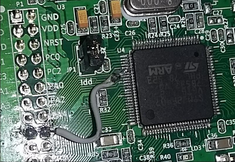
I had been getting the following error from the terminal when trying to access the sdcard on my STM32F4 core: [[35355.231] SD Card Informations [35355.231] ==================== [35355.231] ERROR: Reading CID failed with status -256! [35355.231] ERROR: Reading CSD failed with status -256! [35355.231] [35355.231] Reading Root Directory [35355.231] ====================== [35355.231] SD Card: not connected [35355.232] Failed to open root directory - error status: 12 [35355.232] [35355.232] Checking SD Card at application layer [35355.232] ===================================== [35355.232] Current session: /SESSIONS/DEF_V4L [35355.232] File /SESSIONS/DEF_V4L/MBSEQ_B1.V4: doesn't exist [35355.232] File /SESSIONS/DEF_V4L/MBSEQ_B2.V4: doesn't exist [35355.232] File /SESSIONS/DEF_V4L/MBSEQ_B3.V4: doesn't exist [35355.232] File /SESSIONS/DEF_V4L/MBSEQ_B4.V4: doesn't exist [35355.232] File /SESSIONS/DEF_V4L/MBSEQ_M.V4: doesn't exist [35355.232] File /SESSIONS/DEF_V4L/MBSEQ_S.V4: doesn't exist [35355.232] File /SESSIONS/DEF_V4L/MBSEQ_G.V4: doesn't exist [35355.233] File /SESSIONS/DEF_V4L/MBSEQ_BM.V4: doesn't exist [35355.233] File /SESSIONS/DEF_V4L/MBSEQ_C.V4: doesn't exist [35355.233] File /MBSEQ_C.V4: doesn't exist [35355.233] File /MBSEQ_BM.V4: doesn't exist [35355.233] File /MBSEQ_HW.V4L: doesn't exist or hasn't been re-loaded [35355.233] done. I checked around on the forum and had seen a lot of people having issues with wiring , the card slots and the format on the cards. Mine turned out to be bridged pins under the LQFP100 on the STM32F4 board. Here are the relevant pins if you are having issues as well: LQFP100 P1 PA5 30 15 PA6 31 18 PA7 32 17 PB2 37 24 Here is J16 looking down on it _________ | VS --- VS | -------> to ground | VD --- VD | -------> 3.3V (the STM32 actually only puts out about 3 volts) SI SO | SI ----> PA6 SO ---> PA7 | SC --- SC | --------> PA5 | RC2 RC1 | RC2 --> PD11 RC1-->PB2 (RC1 goes to the onboard SDCard reader or a card on J16 if there is no card in the reader ---------------- RC2 is for a second Card and not needed for most testing. I figured the board was already messed up so I decided to try fixing it. Those pins are super small and hard to work with. There was a dead short between PA6 and PA7 I was able to lift pin PA6 and cut the trace with a razor blade and solder a jumper directly from the pin to PA6. I would think this error would more likely happen from a solder bridge elsewhere and the STM should pass QC. The pins are pretty easy to test as they go straight to the ARM Processor. The also nicely went in order down the side. PA5 was pin 5 on that side of the chip. The white silkscreen on the board makes it a lot easier to keep track of the pins they are marked every 5 pins. The jumper might look a like it is crossing things in the photo but the pin is bent up and out so there is plenty of clearance. I tried solder wik, reflowing the pins, my hot air rework iron, cleaning between the shorted pins with a razor blade, and even removed the header pins hoping the short was there before lifting the pin but nothing else worked for me.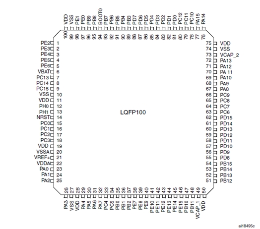

-
Heeft iemand een idee waar je deze in Nederland kan krijgen? Via Distrilec en Mouser betaal je een tientje verzending, en dat vind ik nogal veel voor een onderdeel van 3 euro. Of wellicht heeft iemand er nog eentje liggen die kan overnemen?
-
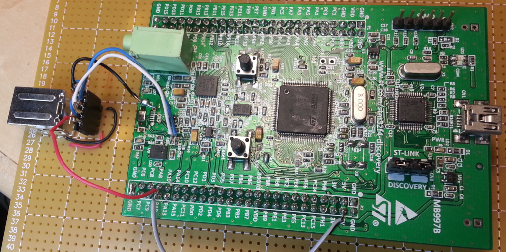
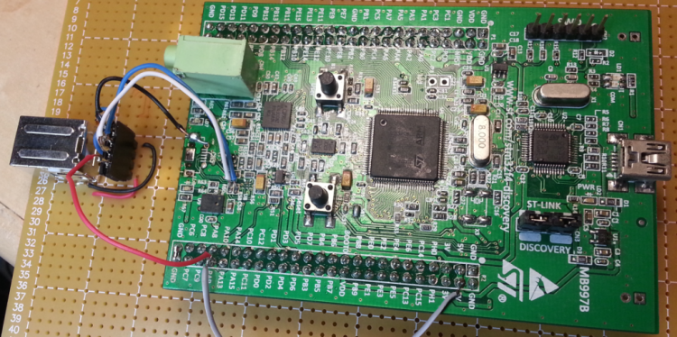
I received my first F4 Discovery board from an Chinese ebay seller along with some excellent value LEDs and an LCD display this week. The F4 was able to be flashed with it's booloader through the ST link as per TK's instructions. It was when I attached the target USB connection that didn't work, that I spent quite a few hours to sort things out. I found: various short circuits under CN5 (the target USB port) USB data line short circuited by a solder bridge. SMD capacitor open circuit (not properly seated) Worst of all(!): CN5 was the wrong kind of connector for this PCB. It was a micro USB receptacle, sure, but one designed for a PCB such that in this case the logo on the cable plug faces down. The result is that all the terminations are made in reversed order(!!!) It took me by surprise after many confused hours. For example why was the Vbus sitting at -0.7V rather than +5V? (Because with power attached backwards the 5V rail was being clamped by the diode action of a nearby logic chip, which was getting warm, btw) Happily, and perhaps miraculously the board is now working (at least the functions that I will be using). I removed the CN5 connector with a hot air gun (after carefully wrapping the PCB in foil to protect the rest of the board from the heat). I soldered 4 wires onto the PCB for the USB connector mounted on the baseboard.
.thumb.png.f0e98c2b6fca00e6f2199b857bfa2979.png)


.png.ce10e7c2c9d3e5b7b02a64bc05fc1fea.png)