Search the Community
Showing results for 'STM32F4'.
-
Here's my complete test configuration, with only the STM32F4 + display + SD card as hardware. RESET_HW EVENT_RECEIVER id= 1 type=SysEx stream="0xf0 0x41 0x10 0x00 0x10 ^ignore ^ignore ^ignore ^ignore ^ignore ^dump ^ignore 0xf7" EVENT_ENC id=1 hw_id=1 lcd_pos=1:1:1 fwd_to_lcd=1 label="FtT1%B" range=0:127 type=SysEx stream="0xf0 0x41 0x10 0x00 0x10 0x12 ^chk_start 0x1f 0x00 0x20 0x55 ^val ^chk_roland 0xf7" syxdump_pos=1:0 EVENT_ENC id=2 hw_id=2 lcd_pos=1:6:1 fwd_to_lcd=1 label="FtT2%B" range=0:127 type=SysEx stream="0xf0 0x41 0x10 0x00 0x10 0x12 ^chk_start 0x1f 0x00 0x20 0x56 ^val ^chk_roland 0xf7" syxdump_pos=1:1 I already figured out that somehow the combination of the encoder event receiving the sysex dumpi (via syxdump_pos), on the one hand, and the sysex the same encoder event is sending, on the other, cause the problem. See the byte highlighted in red above. If the data received and dumped by EVENT_RECEIVER contains that byte (whether it's ^ignored or not), the screen freezes. But if I change the highlighted byte to something else, EVENT_RECEIVER can receive and dump 0x12 as the 6th byte without problems. If I changed the highlighted byte to 0x11, for example, now the EVENT_RECEIVER receiving and dumping 0x11 will freeze the screen. (And of course, removing the stream element from the EVENT_ENC completely has the same effect.)
-
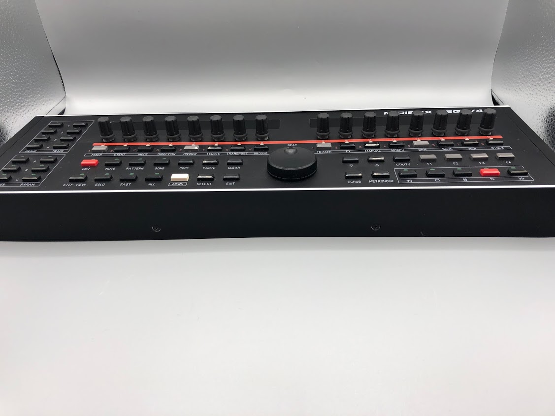
Hey all! A little late to the party, but I'm considering upgrading my stm32F4 Seq 4 to a 4+. I've found what I think is the new hardware config for the frontpannel on this repo https://github.com/midibox/mios32/tree/master/apps/sequencers/midibox_seq_v4/hwcfg Probably a dumb question, but Is there anywhere that just has documentation for the new frontpannel? Like a manual, or something similar? I think I understand how all the labeled functions work, just not 100% sure about the new contextual GP buttons and encoder switches. The whole new thing is really cool! I appreciate all the work yall put into it. thanks, -hal
-
So its not the wiper, but that is indeed a clever possibility! And exactly why I love this forum. You guys always have ideas I'd never think of. Unfortunately, I've got 3 seperate control banks (8 pots each), and they each work fine on the other two MUXes and also exhibit the same weird behavior on the first MUX. Good thinking on the tutorial Antichambre - had forgotten all about the initial AINSER testing I had to do. Ended up just loading the MB128 Controller because it was handy and already has debug messages. Works fine... Each pot has its own pin and its own unique value. Albeit this is all when plugged into J19. My Goom implementation has AINSER running on J8/9 and its associated SPI. Goom uses the onboard DAC of the STM32F4 which uses the same SPI as J19. So I'm thinking the problem must lie in modifications I've made to the AINSER software module... Not sure off the top of my head, what could be causing this rather unique issue, but I'm going to start over again with the original AINSER code and slowly remodify it again. What's strange is that I could swear I had it all working. Then this problem popped up after setting it all aside to work on other projects. Of course that also means there are some major lapses in my memory, so who knows what I did to the code... Again, many thanks for the help - always good to have a few fresh eyes and brains to help regain perspective on this stuff. You all rock! Will report back shortly!
-
I've been implementing analog controls in the GOOM distribution for STM32F4, and thought I had conquered all of my issues with AINSER with much help from the forums. Got all my controls on panels now and wired everything up and have a whole new problem. Only one control on the first MUX chip works. I'm only using 3 chips and the other two work perfectly. I am almost positive that I tested the first MUX chip, but perhaps not... It's acting like the MUX isn't getting the ABC bits to advance through each channel, it just stays on the first channel and AINSER assigns that pot's value to all of the pins on that chip. But ABC on MUX 1 are receiving the same pattern as MUX 2 and 3. Tried swapping MUX chips around with no change. Same with ribbon cables. Really seems like it's a hardware issue, but I can't for the life of me find it. I'm out of time for the day, but plan to rebuild it on the breadboard and see if the problem persists. Could this be caused by software? I can't see anywhere in AINSER that would cause this kind of an issue. To be clear, there are 8 knobs (parameters 0-7). Only one knob generates values and it assigns that value to all parameters (0-7). I built my module with a bit of a weird pin mapping, so the working knob is number 6, but this is the one connected to X0 on the MUX. Which really makes it seem like the MUX just isn't advancing. I can change pin mapping and it still only reads that one knob, thought it does change the order in which it assigns pin values (matching the pin mapping). Any thoughts as to where to look for further testing? Thanks! Jeff
-
One alternative, Will the mackie control, logic control be ported to use on the stm32f4? My daw supports this so I could go that way instead if needed.
-
Winter time is DIY time - and this year I decided to explore the capabilities of the ESP32 platform. There might be synergies with MIOS32, but I'm very sure that I won't fully integrate this Microcontroller into the MIOS32 ecosystem --- this hasn't been considered 10 years ago when I started with the 32bit platform, and it would take too much time to make everything compatible (with many compromises - e.g. no native USB support, and we know that this is important for best performance!) However, I think that ESP32 is a pretty good companion device to a STM32F4, hence potential candidate for future MIDIbox enhancements. E.g. the NodeMCU ESP32 available at Reichelt for 10 EUR supports Dual-Core (!) @240 MHz with WiFi and Bluetooth, 512k RAM, 4MB external Flash, incl. USB programmer on PCB - compare this with a PIC18F*! ;-) I started with Bluetooth, and the result can be found here: https://github.com/midibox/esp32-idf-blemidi This so called "BLE MIDI" service should work with any OS which supports this protocol. So far only tested on MacOS and iOS... but it should also work with Linux and Win10. This will be the basis for further experiments at my side - I'm able to communicate with the device via MIOS Studio. :-) (however, application download has to be done with the ESP32 ecosystem - means: the appr. esptool.py based bootloader) In future also a WiFi connections as demonstrated in Pedalino might be possible, but I'm not there yet - focus is on the application itself, knowing that the MIDI interface options won't be so fast like known from the STM32F4 based platform. E.g. how accurate can we control a Motorfader with the PWM LED outputs of a ESP32? If it works, it could be connected like a MBHP_MF_NG module via traditional UART based MIDI to a MIDIbox NG. And will it be possible to control a SRIO chain? Might be interesting for a future BLM16x16+X with (only) optional WiFi and Bluetooth connects. Best Regards, Thorsten.
-
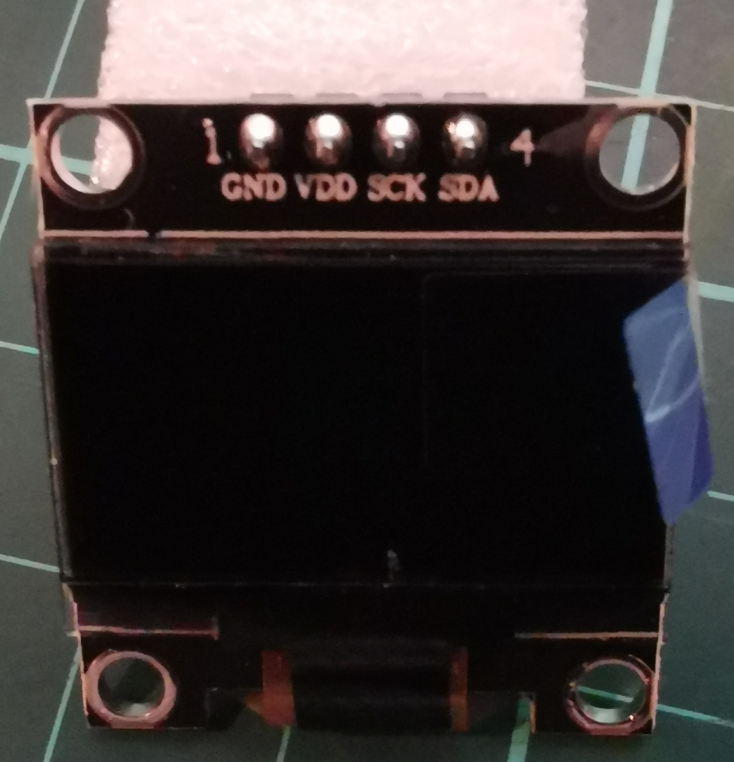
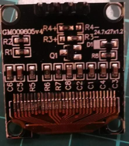
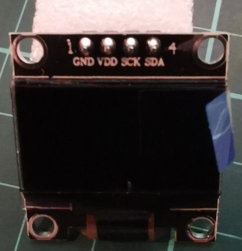
My ssd displays turned up today. Looks like I got messed with. These are not the ssd1306 glcds I needed. These have only 4 pins on, I'm guessing they are not compatible with the stm32f4. Anyone know if these will work or if I need to try and get the 16 pin parallel ssd displays?
-

LoopA V2 Introduction, Features & Support Thread
Hawkeye replied to Hawkeye's topic in MIDIbox User Projects
@Phat, that sounds great! At some point in time, the LoopA software will probably get a CC track type, but it will never be as powerful as your dedicated CC Looper, that can just use the full STM32F4 memory for that single purpose :) Many greets, Peter -
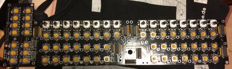
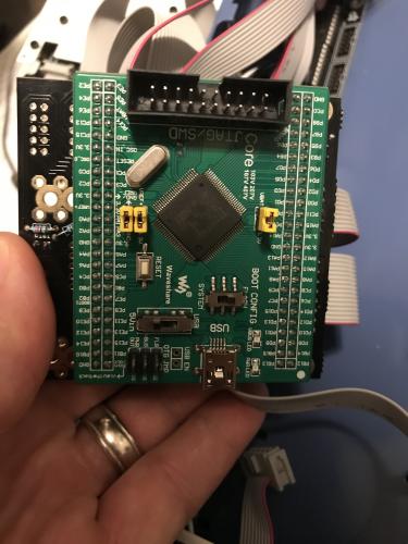
Hi! We are building MIDIBox v4 from the PCBs ordered from Modular Adict https://modularaddict.com/midibox-seq-pcb But could not find the instructions for this exact board (just Wilba's), and now we have a problem that it sends out weird messages to the STM32F4 core. The unit starts up fine, but as soon as any button is pressed or encoder turned, the screen gets weird characters and it seems all the controls are messed up. We suspect the Resistor network might be the problem, that is not the same specification as needed, we used this: https://lomex.hu/pdf/(bou)_4600_serie.pdf Also it is a question if the encoder pinout is correct and if it needs the arrangement suggested by Hawkeye in this comment? Any help please what is the problem? I attach the picture of the current stage of the PCB build.
-
I've moved the AINSER_Scan task back to app.c and SYNTH_Update back to APP_Tick just to make sure I'm not introducing any new issues of my own making, but am still with the same results. Are there any other applications using both the Audio DAC of the STM32F4 and an AINSER module? The only similar synths I could find in tutorials or apps didn't utilize AINSer. Posted the main functions at issue below. SYNTH_Init is where things seem to go wrong. Right now I've got the return MIOS32_I2S_Start commented out - this is the only way I can get AINSer to function and return values. Swapping it with return 0 allows the synth to function, but no AINSER controls work, nor does the pulsing link light on the module ever light. I don't think I have any SPI conflicts, but the SPI_Start sure seems to be the culprit. I'm a little over my head in this project - any thoughts on how to approach debugging this further? Thanks! Jeff #define PRIORITY_TASK_AINSER_SCAN ( tskIDLE_PRIORITY + 3 ) static void TASK_AINSer_Scan(void *pvParameters); void APP_Init(void) { // initialize all LEDs MIOS32_BOARD_LED_Init(0xffffffff); // initialize the AINSER module(s) AINSER_Init(0); // start task xTaskCreate(TASK_AINSer_Scan, "AINSerScan", configMINIMAL_STACK_SIZE, NULL, PRIORITY_TASK_AINSER_SCAN, NULL); // init Synth SYNTH_Init(0); } static void TASK_AINSer_Scan(void *pvParameters) { portTickType xLastExecutionTime; // Initialise the xLastExecutionTime variable on task entry xLastExecutionTime = xTaskGetTickCount(); while( 1 ) { vTaskDelayUntil(&xLastExecutionTime, 1 / portTICK_RATE_MS); // skip delay gap if we had to wait for more than 5 ticks to avoid // unnecessary repeats until xLastExecutionTime reached xTaskGetTickCount() again portTickType xCurrentTickCount = xTaskGetTickCount(); if( xLastExecutionTime < (xCurrentTickCount-5) ) xLastExecutionTime = xCurrentTickCount; // scan pins AINSER_Handler(APP_AINSER_NotifyChange); } } static void APP_AINSER_NotifyChange(u32 module, u32 pin, u32 pin_value) { // toggle Status LED on each AIN value change MIOS32_BOARD_LED_Set(0x0001, ~MIOS32_BOARD_LED_Get()); DEBUG_MSG("APP_AIN_NotifyChange_SER64(%d, %d, %d)\n", module, pin, pin_value); SYNTH_AINSER_NotifyChange (module, pin, pin_value); } s32 SYNTH_Init(u32 mode) { // use J10A.D0 for performance measurements MIOS32_BOARD_J10_PinInit(0, MIOS32_BOARD_PIN_MODE_OUTPUT_PP); // start I2S DMA transfers //return MIOS32_I2S_Start((u32 *)&sample_buffer[0], SAMPLE_BUFFER_SIZE, &SYNTH_ReloadSampleBuffer); return 0; }
-
I've been slowly working on integrating analog controls into the lovely Goom port for the STM32F4 and hit a bit of a roadblock. The AINSer64 module won't initialize (no pulsing link light). I can get it to work only if I disable the last line of the following function. Commenting it out and returning 0, allows the AINSer64 to do its job, the link led pulses and turning knobs send debug messages with proper pin numbers and values. The Goom synth also works just fine without any of the AINSER code present. Currently the AINSER64 is setup on J19 / SPI 2. s32 SYNTH_Init(u32 mode) { // initialize the AINSER module(s) AINSER_Init(0); // start task xTaskCreate(TASK_Synth_Update, "SynthUpdate", configMINIMAL_STACK_SIZE, NULL, PRIORITY_TASK_SYNTH_UPDATE, NULL); xTaskCreate(TASK_AINSer_Scan, "AINSerScan", configMINIMAL_STACK_SIZE, NULL, PRIORITY_TASK_AINSER_SCAN, NULL); //use J10A.D0 for performance measurements MIOS32_BOARD_J10_PinInit(0, MIOS32_BOARD_PIN_MODE_OUTPUT_PP); // start I2S DMA transfers return MIOS32_I2S_Start((u32 *)&sample_buffer[0], SAMPLE_BUFFER_SIZE, &SYNTH_ReloadSampleBuffer); } I2S is enabled in the config file. I saw that it can conflict with the SRIO SPI, tried setting SRIO_SPI to 0, with no luck. I wasn't sure if that applied here or not. Have tried this same code with ReloadSampleBuffer as an empty function, with the same results. I'm assuming the issue is somewhere in the I2S_Start function, but reading through that I didn't notice any obvious issues. Other AINSer apps like MIDIO128 work fine. I did have issues with the Jitter Monitor though - it just scrolls endlessly, returning empty results for all modules. I haven't delved deeper into that since the module was returning results without any issues outside of trying to implement it in Goom. Any insight into what might be happening here? Thanks Jeff
-
Hello, i've got a small (i hope so) problem with parts i want to order at Reichelt.de. The 74HCT 541 by Texas Instruments is not available any more, nor at reichelt or at mouser. For building a STM32F4, can one use 74HC 541 instead ? Thanks in advance, Martin
-
I am not familiar with that software but you want to see what your 3.3 is doing. Is it actually 3.3 at startup? Maybe something is pulling it down or it is not actually 3.3v are you getting some noise on the 3.3 line. You should not need to export it but just take a picture of the screen. You should be able to test most of this with a voltmeter but if it is happening right at startup the meter might miss that and will not show a spike or excessive noise. Does it dip on startup, does it have a big pulse on startup? Also when you have all your devices connected when the problem is occurring is the voltage still 3.3v or it could say be dropping below 3v causing your problems. Maybe part of your circuit has a solder bridge or bad cap that is pulling the voltage down. The thought on the midi io versus the iic midi is it would be using a different 5v power supply so may workaround what ever is pulling the voltage low if the voltage is being pulled low somehow say by a midi cable or connected device that is going bad and is loading the system. Don't rule out issues on the processor board either get out a magnifying glass, your volt meter and test everything back to the processor pins for the sd card. Also test with it not powered for impedance. I have had a stm32 board that had a pin for the sd card with a solder bridge new from the factory at the mcu leg it is possible and fixable by lifting the offending pin leg. (they are really small and hard to work with don't mess with this unless you have 100% verified it is the issue) Not saying this is your exact problem, especially since you are using a lpc board but I would get the manual for the LPC and check everything like this: http://midibox.org/forums/topic/20396-stm32f4-sdcard-reading-cid-failed-with-status-256-solved/#comment-177754 It could also be a bad solder joint on one of these pins where the connection in intermittent sometimes it is helpful to use the beep function on the meter to locate this issue as the meter will not beep with a very light touch but as you press down slightly if makes the contact good. You should be able to actually see that with your magnifying glass if one of the pins is not wet out with solder. Since your problem is intermittent and not 100% all the time I would be on the hunt for impedance issues and not exactly a full on short between adjacent legs of the mcu as well as all the other things mentioned above.
-
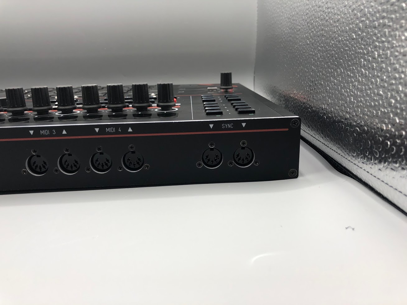
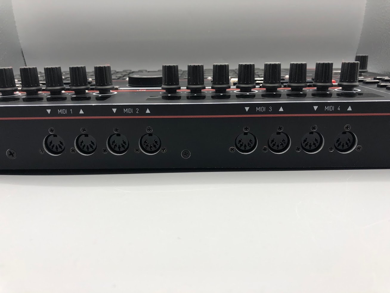
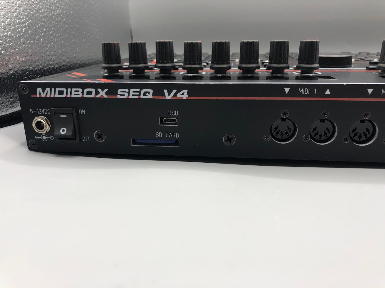
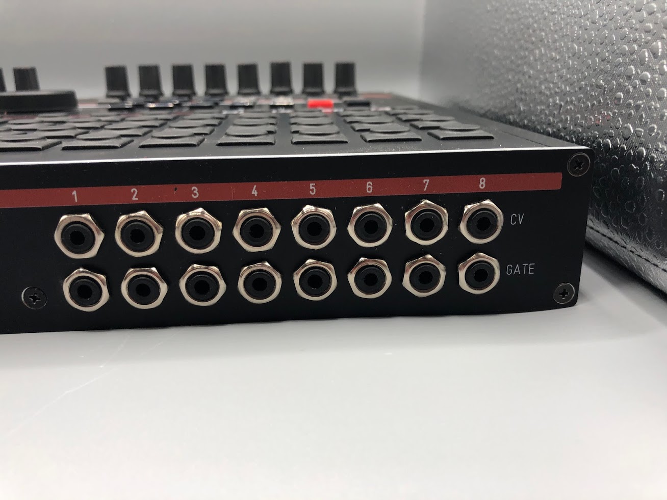
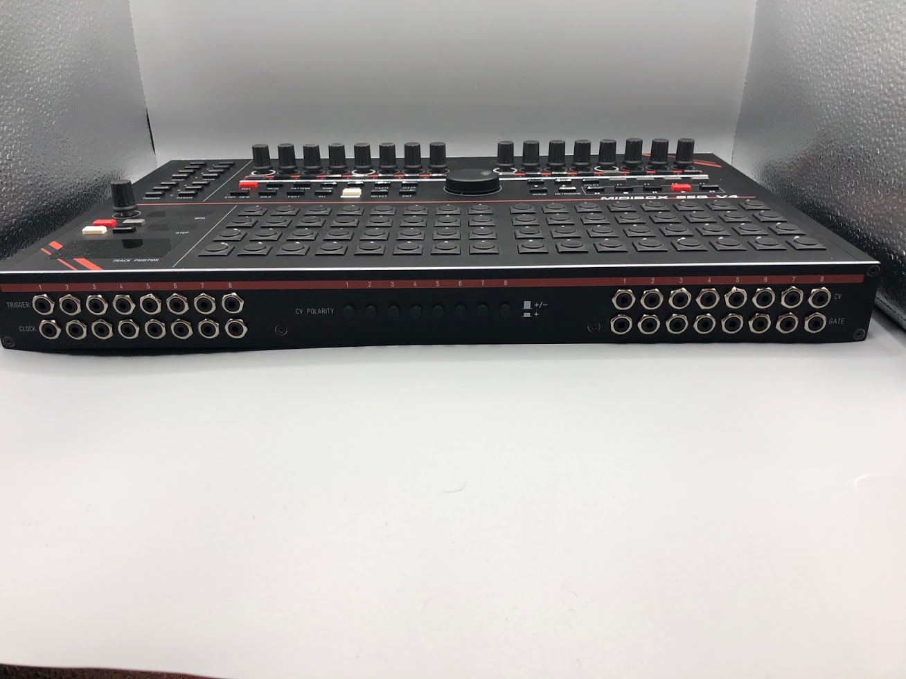
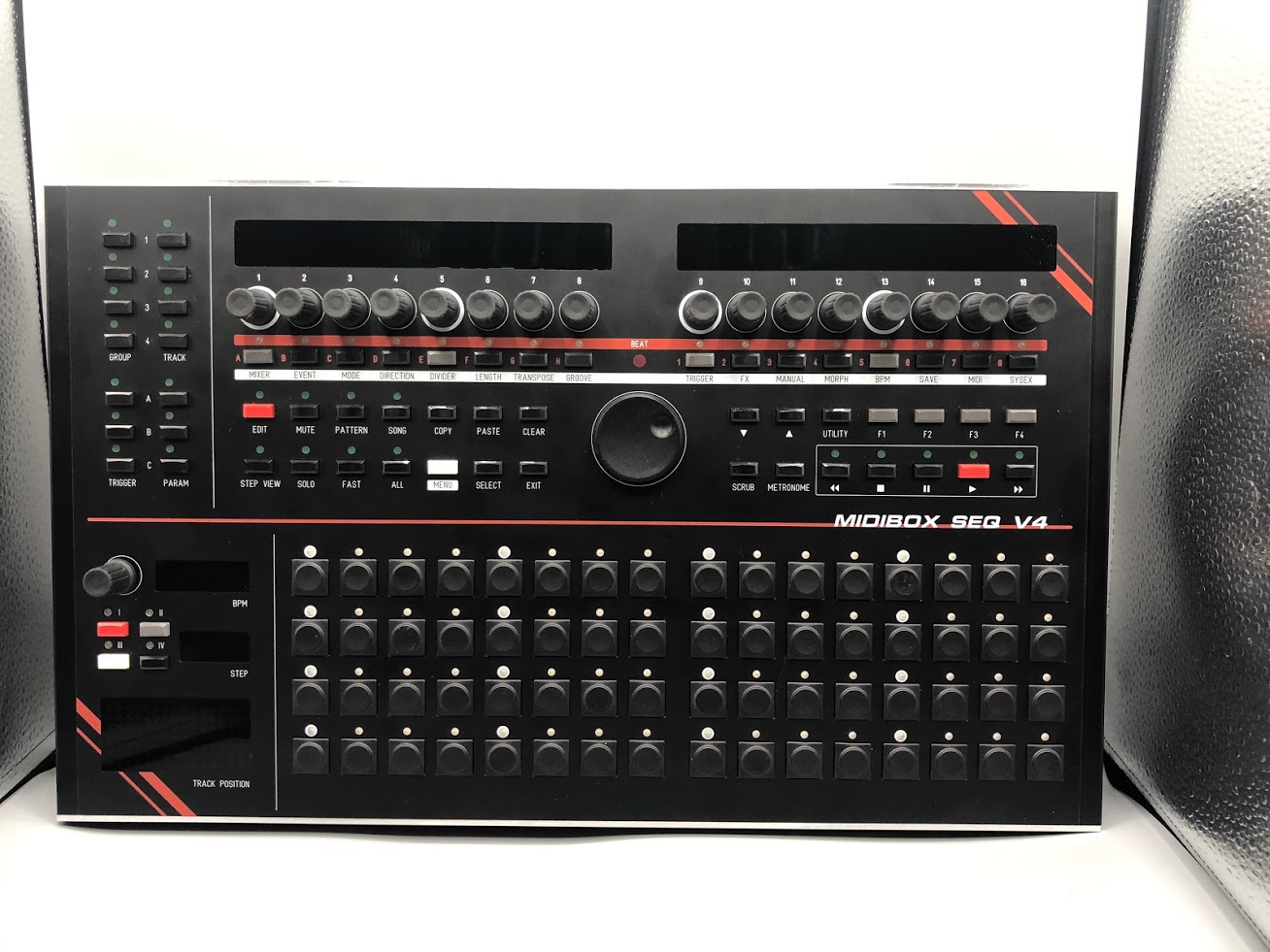
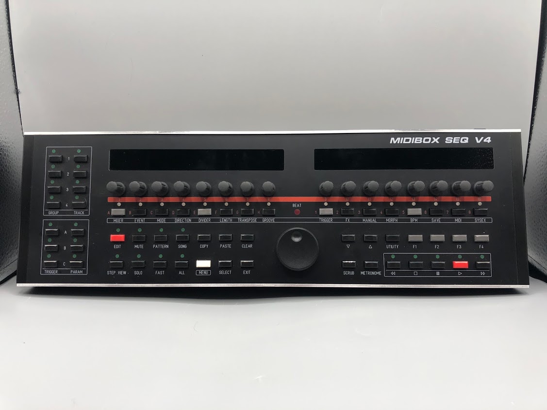
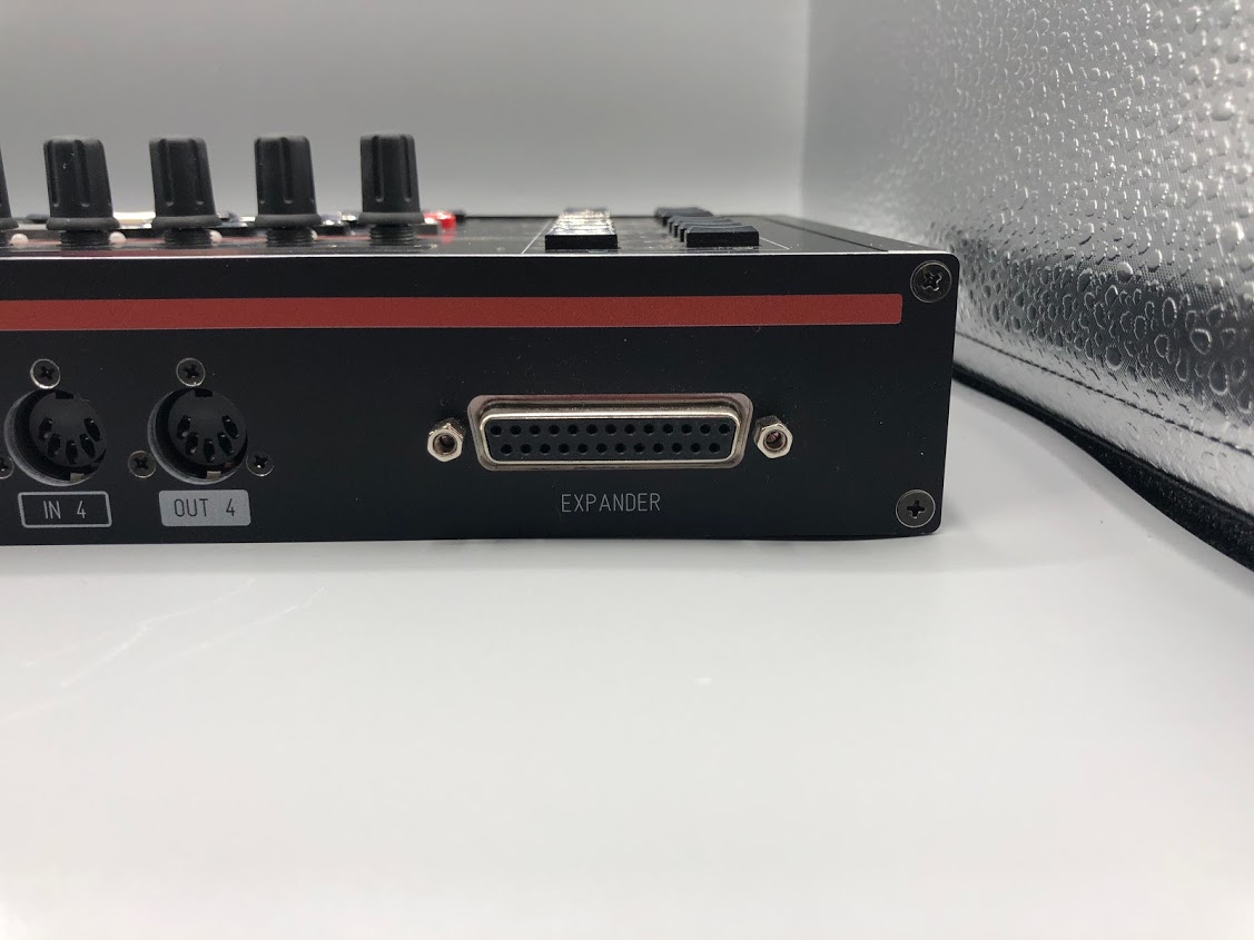
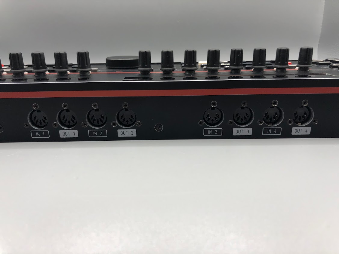
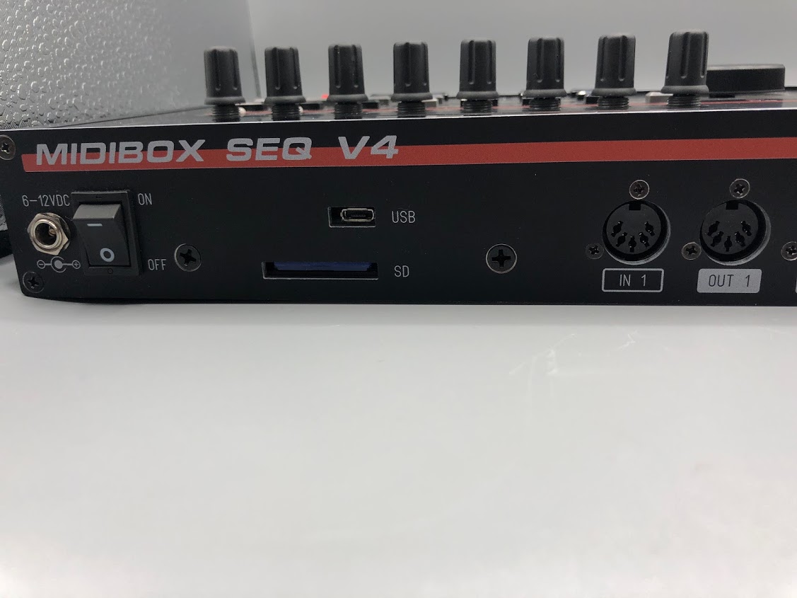
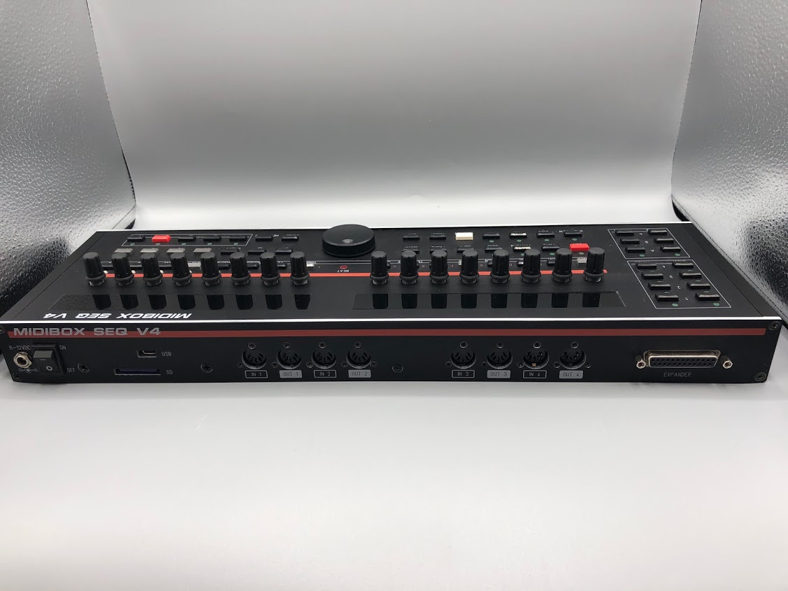
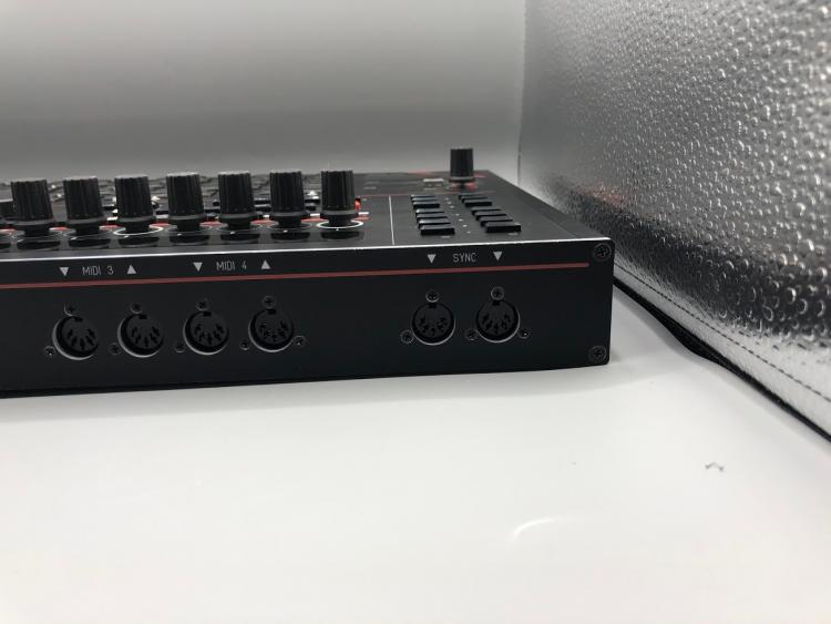
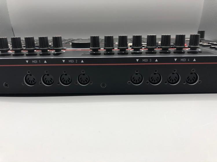
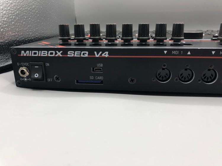
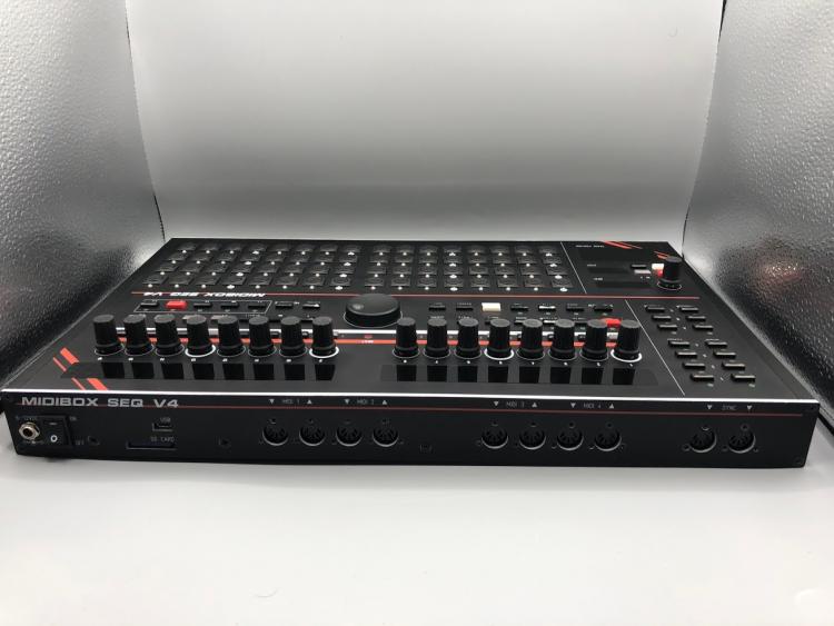
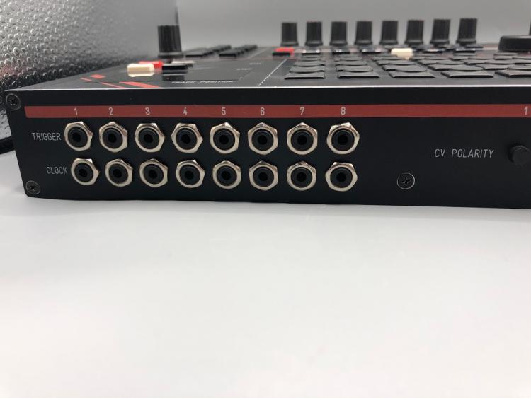
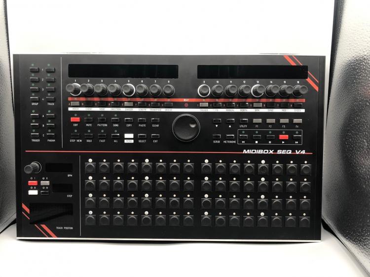
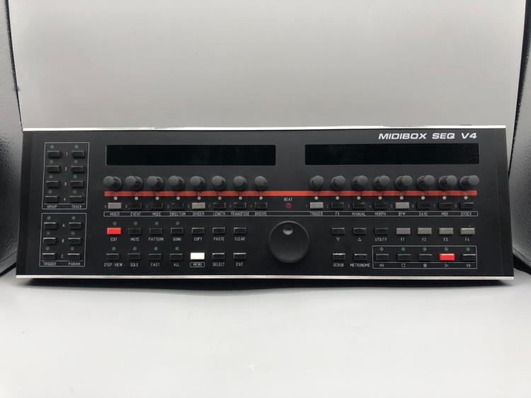
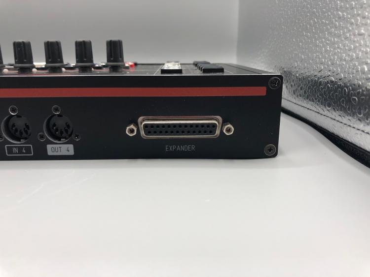
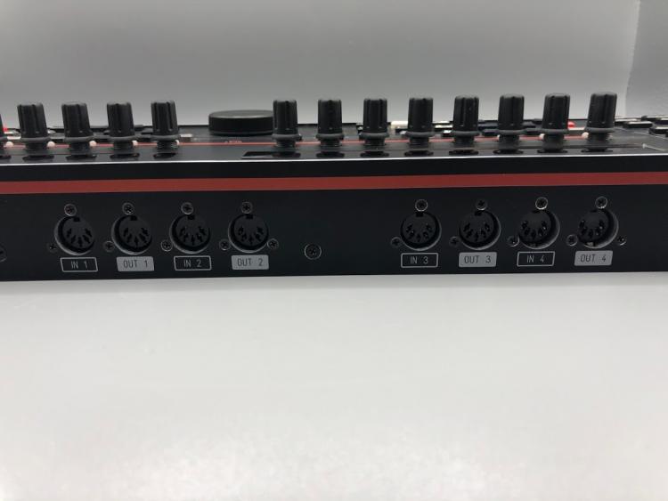
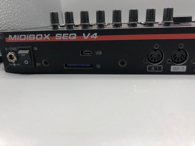
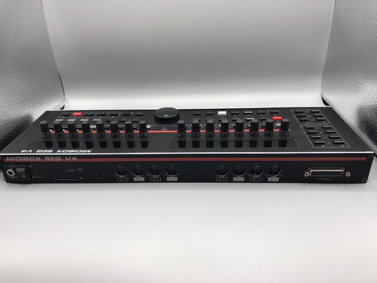
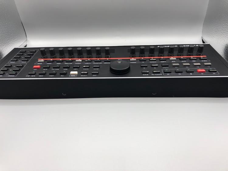
Sale Pending - I'd like to sell my MidiBox Seq V4 with integrated BLM 16x4 expansion and CV/Gate/Trigger/Clock outputs. This unit was built with a STM32F4 core, 2 Midi I/O (4 in/4 out), 2 Din Sync, 8 CV, 8 Gate, 8 Clock, 8 Trigger outputs, white OLED screen, and custom aluminum extruded case and panel. Happy to answer any questions about it. Asking $850 USD + shipping.


-
I'd like to sell my MidiBox Seq V4. It was built with an STM32F4 core, 2 Midi I/O boards (4 MIDI in and 4 MIDI out), green OLED display, custom extruded aluminum case and panel. Happy to answer any questions about the unit or its build. Asking $650 USD + shipping.
-
 Hi, you're welcome, If I was you I will read the DAC Application Note Then find some examples or a library to try with something basic... https://www.st.com/content/ccc/resource/technical/document/user_manual/59/2d/ab/ad/f8/29/49/d6/DM00023896.pdf/files/DM00023896.pdf/jcr:content/translations/en.DM00023896.pdf http://stm32f4-discovery.net/tag/dac/ Then try to adapt it to my need... Note: MIOS32 uses StdPeripheral Library and CMSIS located in Driver folder, no HAL Take care about the DMA and Timer already used. Good luck! Best regards Bruno
 -
@TK. if you have time, would it be possible to define a requirements list of UI features (OLED real estate required, encoders, switches, 3.5mm eurorack input and output ports) that you would like to see in a new dedicated future MBCV module? :) We were lately discussing/planning a new STM32F4 based digital oscillator eurorack module which may have quite similar UI requirements - that way we might get away with a single set of PCBs that could satisfy two usecases! :). 50mm max depth is a given. Many greets and best regards! Peter
-
Hello Guys! I read multiple topics here but I did not find answer exactly to that issue what I have and want to solve. I made a Midibox NG with STM32F4, Ainser64, DINs, etc. I found how to configure buttons and encoder behaviour, all is working great, but I am stucked with potentiometers, especially how to setup higher resolution and get the correct midi output what Traktor Pro can ‘’eat’’. In NGC file I made resolution=9..10..11 bit, range=0:511, 0:1023, 0:2047, depending on the bit depth setup, but all I got as midi signal is that the former 0...127 range (this was the range in 7 bit from CCW to full CW potentiometer turn) is divided multiple times to 0...127, 0...127, etc. ranges. I tried NRPN and Pitchbend type too, but no success. Am I doing sthg wrong, or MB NG is not supporting this in that way how I am thinking? I would to control Traktor Pro pitch fader with a higher resolution, and with the mentioned ‘’divided’’ range, the pitch fader is not becoming more fine, and jumping back when CC changes from 127 to the next 0..127 range. I am not sure that I wrote it correctly what I want, but hopefully understandable. I would have in a +/- xy % pitch range the finest resolution which is possible to achieve with MB NG and works well with Traktor Pro. Traktor is reacting to CC message, and 7bit resolution gives 64-64 steps from center to negative and to positive pitch range. This coarse resolution I would like to change to more fine steps. It reacts to NRPN and Pitchbend messages too, but I could not achieve the same behaviour with higher resolution, like when CC is sent (xy steps in both directions from the center) Is it possible to do the a.m higher resolution fader steps with MB NG with CC, or NRPN, or Pitchbend event? Many thanks for all of you for further help. Akos
-
Just want to share, that the new Behringer RD-8 drummachine is using a STM32F405. Maybe MIOS is an option as an alternative Firmware for those of you who own one.
-
Thanks for the quick reply. BTW... My bad,,, it is a waveshare. I didn’t restart MIOS studio, but did rescan for devices. It was working completely until I replaced the NG firmware with the SEQ. If I have to re-flash... do I follow the instructions for the stm32f4 on the ucapps website? http://www.ucapps.de/index.html?page=midibox_seq.html What is refflashing from boot loader hold mode?
-
I have: 2 x MBHP_CORE_STM32F4 complete with stm32f4 discovery. 2 x MIDI IO 2 x DIO_MARIX module 1 x AINSER 1 x LCD 20x4 I'm not using. Located in Sweden. Give me a fair offer and it yours. Prefer contact via email as I rarely check the forum: albin.stigo@gmail.com SOLD Best regards, Albin Stigö
-
Hi, i am starting projecting custom stereoSID board based on STM32F4-disco dev layout (but no discovery board, only the mcu), since PICs are already outdated, can the PIC SID firmware be ported to STM32? I am working at evenings in local company having access to Autotronik machine which can do all smd hardwork. After the finish i will share the board if anyone want to build the same. PS It's planned as mostly smd, besides SID and some hard-to-locate components. And may be i'll orient it as board for ArmSID or SwinSID only because then it will have 5v only power supply, thoughts? edit: i didnot noticed i have sources for 2.044. I'll try to dig what's inside the code.
-
Hi! First, let me introduce myself. I'm Thomas, sound engineer, I'm working mostly in audio post but have a small home studio where i record small bands. It's been a long time since i started thinking about making a midibox NG, but other projects kept me busy (I built a few preamps for my home studio as well as other audio gears) But now, i finally have time and hopefully make it a reality. I will try to keep this thread updated with my progress and experiments. So first, i'll expose what i'm aiming for: My goal is to build myself a Midi controller that is basically a Mackie Control with a few more features to control Nuendo. I really want it to be as ergonomic as possible, and today, no controller on the market would fit my needs completely. (maybe Nuage systems, but that's a bit expensive) Midi-wise, i will use 3 ports as Mackie Control and one as a Generic midi. (feature that you can set as you wish in Nuendo) I want: -25 faders: 24 using MAckie Control and MC expanders + one using Generic Midi to control selected channel in DAW -Each fader will have 4 buttons, an encoder with led ring and an oled display on top (just as any MCU) -transport buttons -various array of buttons with MC features as well as window management, automation features, some edit functions... -a Jog wheel -a surround panner -one bank of encoders to control selected channel EQ -another bank of encoders to control Selected channel Dynamics -Control-room commands. I think that's it for wanted features. Now for things i will need: As i understand i'll need: -2 STM32F4 Core module (1 main and 1 for MF_NG modules) -4 MF_NG modules -a bunch of DIO matrices for buttons and LEDs. -and probably an AINSER8 module. I already own a STM32F4disco and i made my own version of the core module. I went through the tutorials, and i've been playing a bit with a beaboarded Din / Dout. Joined is a block diagram of the way i think My different modules will fit together. Hopefully i got this right... I still have alot to do / learn, but feeling really excited about it right now! And i'd like to thank Thorsten and everybody involved in the midibox project for all they have accomplished. This is great! Cheers, Thomas Block diagram.pdf
-
Hello, This is an introduction for my new baby, a really funny toy, the HAARP (yes I like conspiracy theory ;) It's a pure MIDIbox Project, just a dedicated CS and some coding. It works with any STM32F4 Core. Why? Many synths have an integrated arpeggiator, the SH-101 is well known for that, but the available parameters are still limited. There is also some good plug-in I think especially of the Ableton live's one but it's software. So I designed an hardware one, "LIVE" oriented, starting from the @TK.'s arp example. No encoder(except for MENU section Data entry), all parameters are directly accessible and are potentiometers. The screen is a small color TFT with a resolution of 128x160(sorry for picture, colors are better in real). It's 8 independent voices. 8 banks of 8 Presets. Session are saved/loaded from the SD Card. The Arpeggio parameters are divided in 3 sections: First is the TIMING Section (Purple pots): On/Off button, HOLD Button, it holds or releases the Notes in the notestack. The MODE Pot, it's UP, DOWN, UP-DOWN and AS-PLAYED, fr the moment but I will implement more. The RATE, from slowest to fastest, from 4 Bar to 32nd with dotted and Triplet value. The RESYNC, it retriggers the arpeggio, values are the same as RATE parameter. The OFFSET, it will shift left or right the starting step(note). Is Note Stack and MODE dependent. The DELAY, it will delay the whole arpeggio within the step range(duration), is RATE dependent. The GATE, the length of the Note, max is STEP length, is RATE dependent. The SHUFFLE, it will delay all the odd steps, in the range of an half step, is RATE dependent. Second is the TRANSPOSITION Section (Yellow, Orange, Red): Simple Transposition On/Off (Yellow). Simple OCTave Transposition, +/- 10. Simple SEMItone Transposition, +/-12 Repeat On/Off. Repeat, LOOPS number, 1 to 8. Repeat, SHIFTing on each loop, +/-32 semitones. Force to Scale On/Off Force To Scale, SCALE, list is the same as the Force to Scale example from the repo. Force To Scale, ROOT from C to B semitone. Third is the VELOCITY Section. REGEN Pre/Post(Target process) button. REGEN, +/- 100% Target process On/Off. TIME, the time to reach the target value, in PRE initial value is the regenerated value. in POST initial value is the one stored in the Note Stack. TARGET is the targetted value, 0 to 127. RETRIG, if on the TIME is retriggered by the RESYNC parameter. The main page of the screen represents an octave range, the note color changes depending on the octave, there's a Velocity section on the bottom, it's like a piano-roll. In the code, the arpeggio processing is ready, it remains me to complete the MENU section, I was waiting for the CS PCB to write it, now I can... ;) This little guy is to much fun, so I can't keep it for me. Then i will propose it to you ASAP. and I hope it will help me to finance some other bigger projects I've got in my back-pocket ;) I will try to make it available in two format, I'm currently working on a PCB for USB host/device, sdCard MIDI etc.. which will fit for both version and will be reuse for other small toys like that. An Eurorack version for the patching addicts. I used a MCP3204(4 channels) instead of a MCP3208(8 channels) for the AINSER, it's an AINSER32. I use only 2 channels for the 16 pots(8Multiplexed lines * 2 channels), it remains 16 analog Inputs which are accessible to connect some CV In Modules, thanks to @Hawkeye for making me think about this. The SRIO Chain is available too, you can connect GATE In (DIN) easily. You will be able to connect the MIDIPHY CV/GATE Out Modules which will be available soon. @latigid on is working on it. MCAN will be available, for an internal MIDI bus within your Eurorack, I reuse the BUS1 and 2 from the Euro Power connector for that purpose. A Desktop version, for MIDI purpose only(except if i find a way to add some CV/Gate without designing a too much big box). Voilà! More information will be available soon. For the moment this is a small video I made, I seem a little febrile but it's because I continue to discover it every day. I really love this little toy, it is very effective and musical, even in LIVE and if the Force To Scale is activated, there's no wrong note ;) Best regards Bruno
-
 Hello everyone, I am completely new to MIDIbox. I am trying to get the first tutorial to compile under Ubuntu 18.04 for Core 32 STM32F4 and get the following error message : > make -s Creating object file for strtol.c /home/sojastar/Documents/Programmation/MIOS32/mios32/programming_models/traditional/strtol.c:147:19: error: expected ')' before '(' token _DEFUN (_strtol_r, (rptr, nptr, endptr, base), ^~ ) This is from a fresh ( probably faulty ) install of the toolchain : I first cloned the git repo for MIOS32 then installed the latest arm toolchain following these instructions : https://gnu-mcu-eclipse.github.io/toolchain/arm/install/ I did add the toolchain path to my PATH. Any advice or pointer would be greatly appreciated ! Thanks ! Julien