Leaderboard


Popular Content
Showing content with the highest reputation since 10/02/2022 in Posts
-
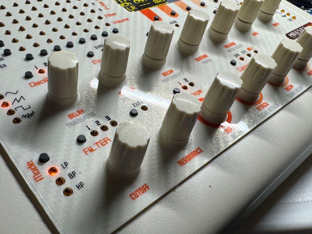
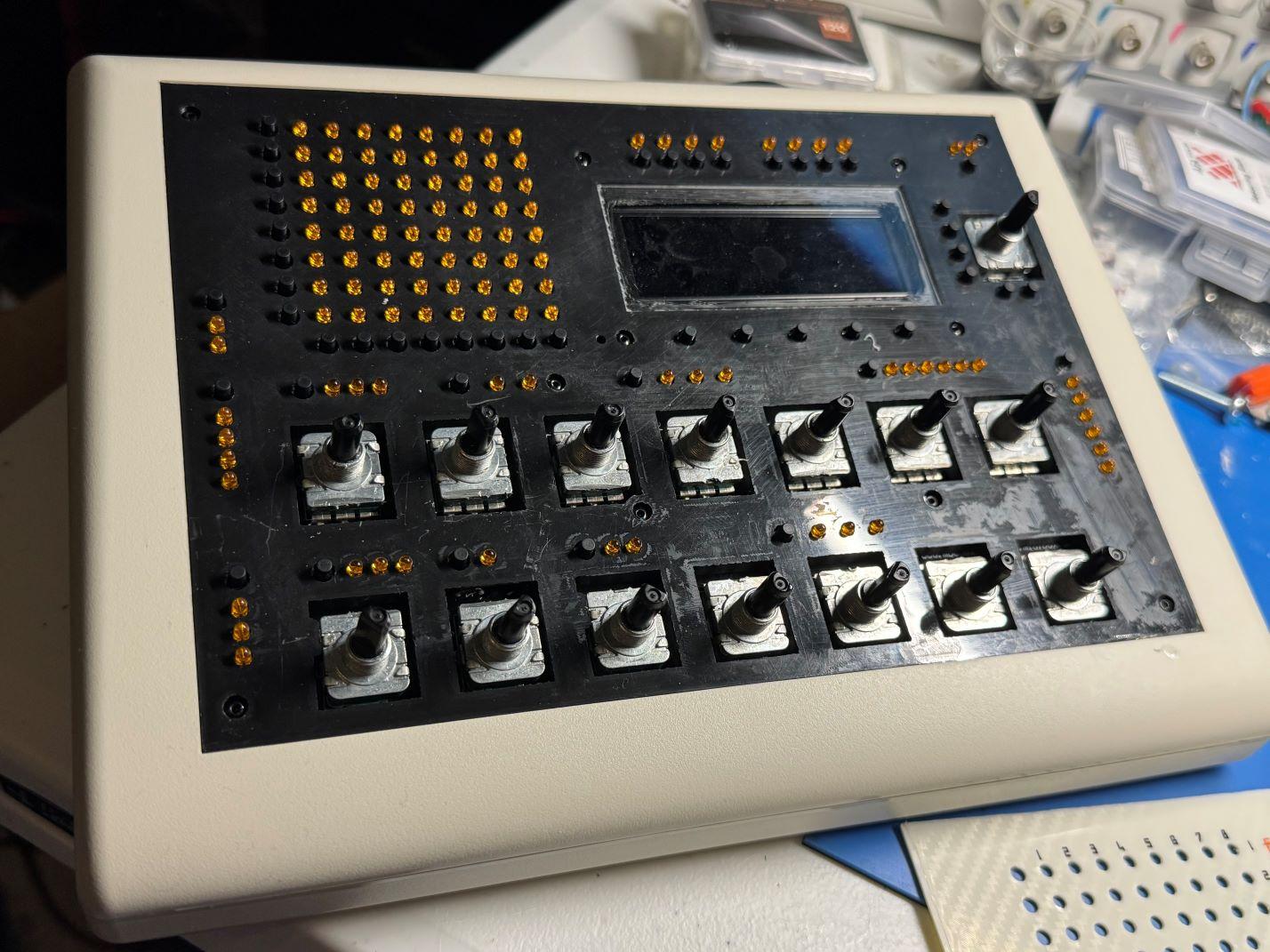
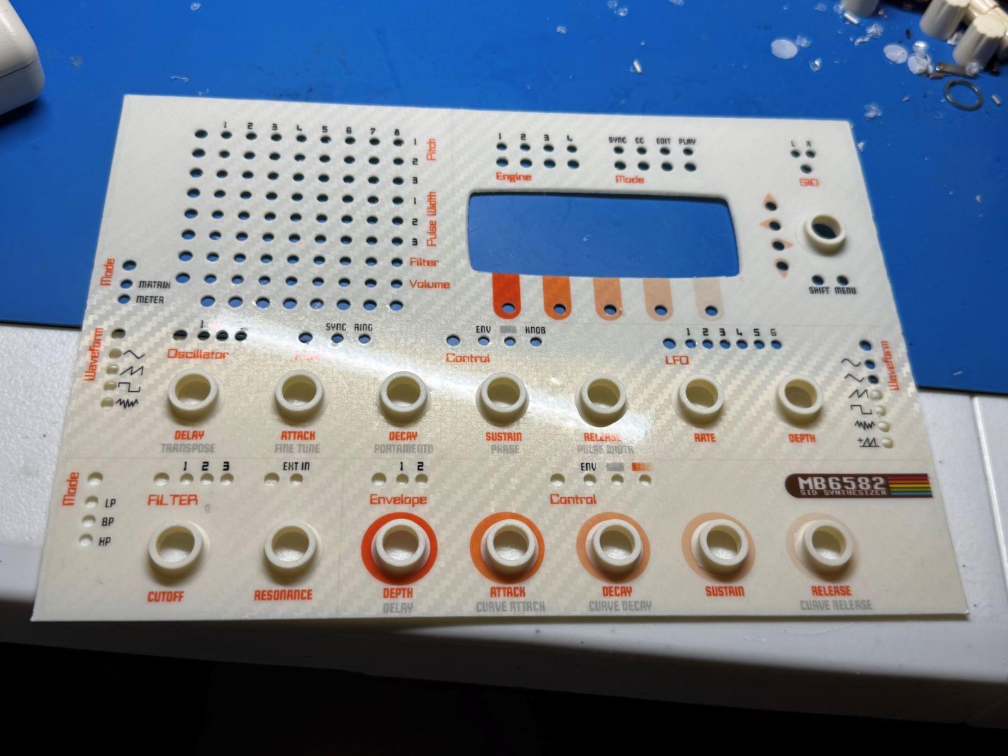
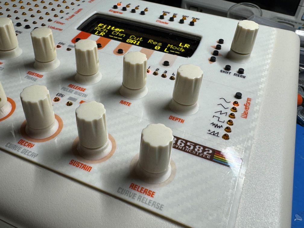
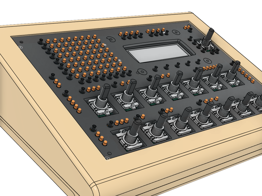
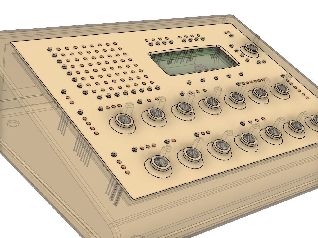
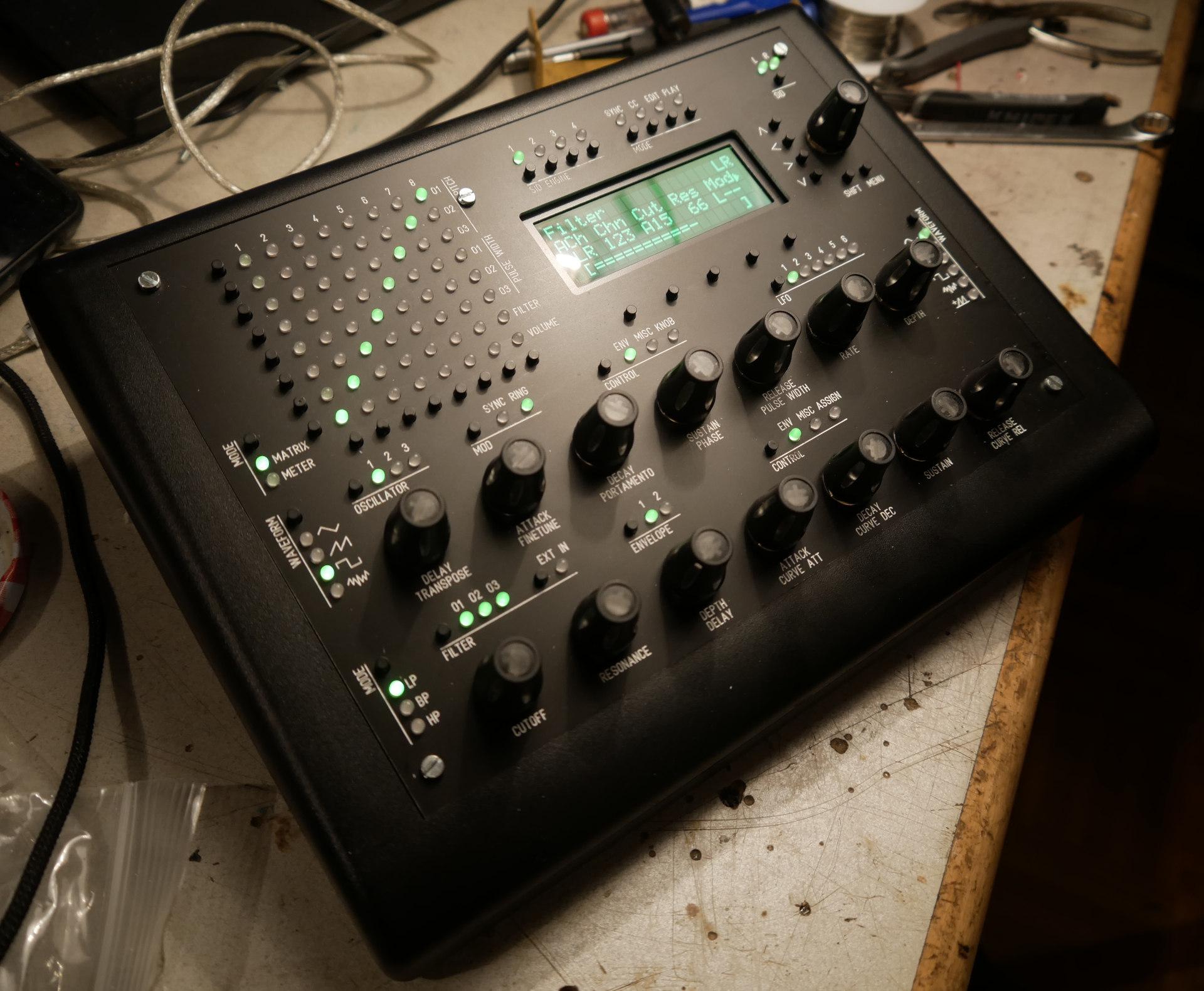
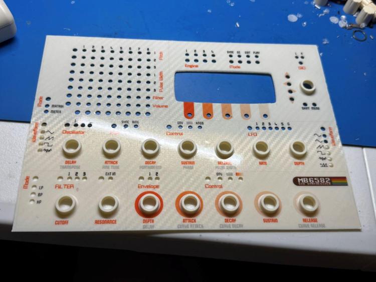
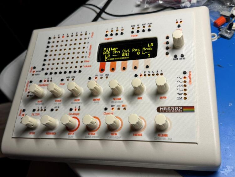
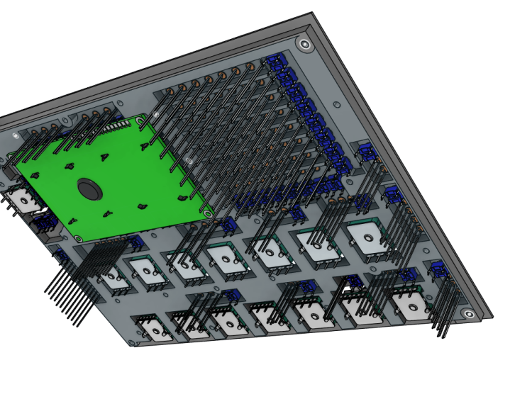
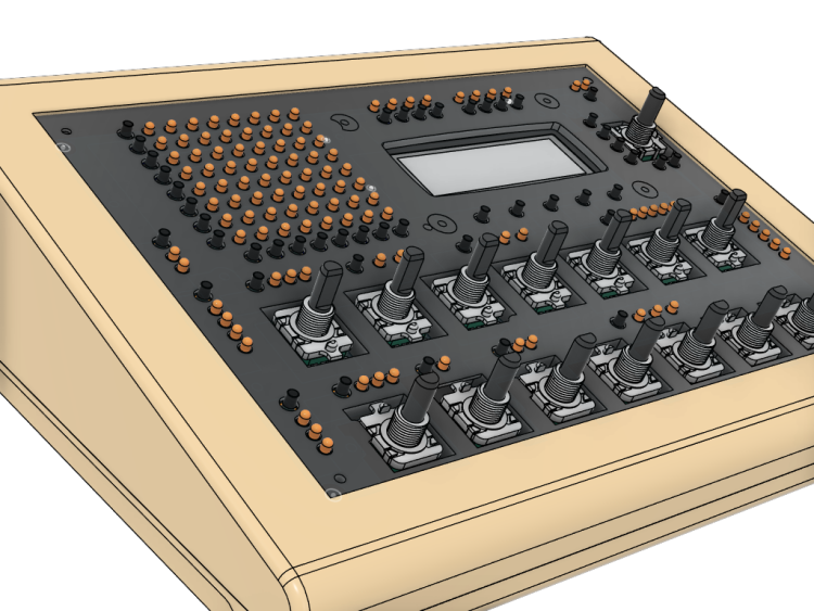
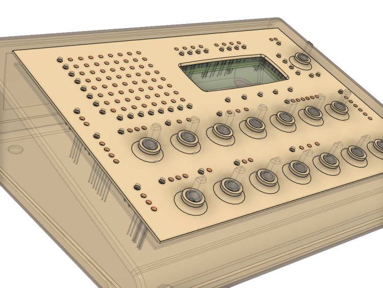
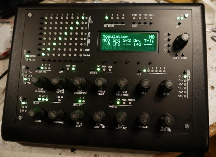
Hey everyone, just wanted to share my latest build since I'm sure there are some 3D printing enthusiasts here like myself. I bought the parts for an MB6582 about 5 years ago, if you remember Meeblip was selling those 8580 SID chips and I picked up 8 of them, and then put everything into a box in a closet . 3D printing has come a very long way since the original MB6582 was created by Wilba. I read that the JB Weld solution may or may not be holding up great after all this time. Also, I wanted to use a Newhaven OLED which is much thinner than the original LCD. I thought there must be a solution to lower the gap distance so why not create some type of spacer for between the front panel and the PCB? I designed all parts in Fusion360. The PCB screws directly into the spacer using M2.5 nuts/screws and plastic screws. The top of it has a flange that rests in the panel groove for the PT-10. Total spacer height is 5.7mm which is the height of the base of the encoders. The front panel is another 1.25mm. Everything is printed out of ASA, which is very strong and heat resistant. I designed the panel graphics in Inkscape and printed on translucent vinyl. I used Davies knobs with small printed skirts to cover up the threads of the encoders since they were exposed. I do not have a vinyl autocutter but I do have an exacto and lots of patience Overall tried going with a 80s beige computer look. A build plate for my printer created the carbon fiber effect on the panel. I'm happy to share the 3D files if anyone could use them.


 3 points
 -
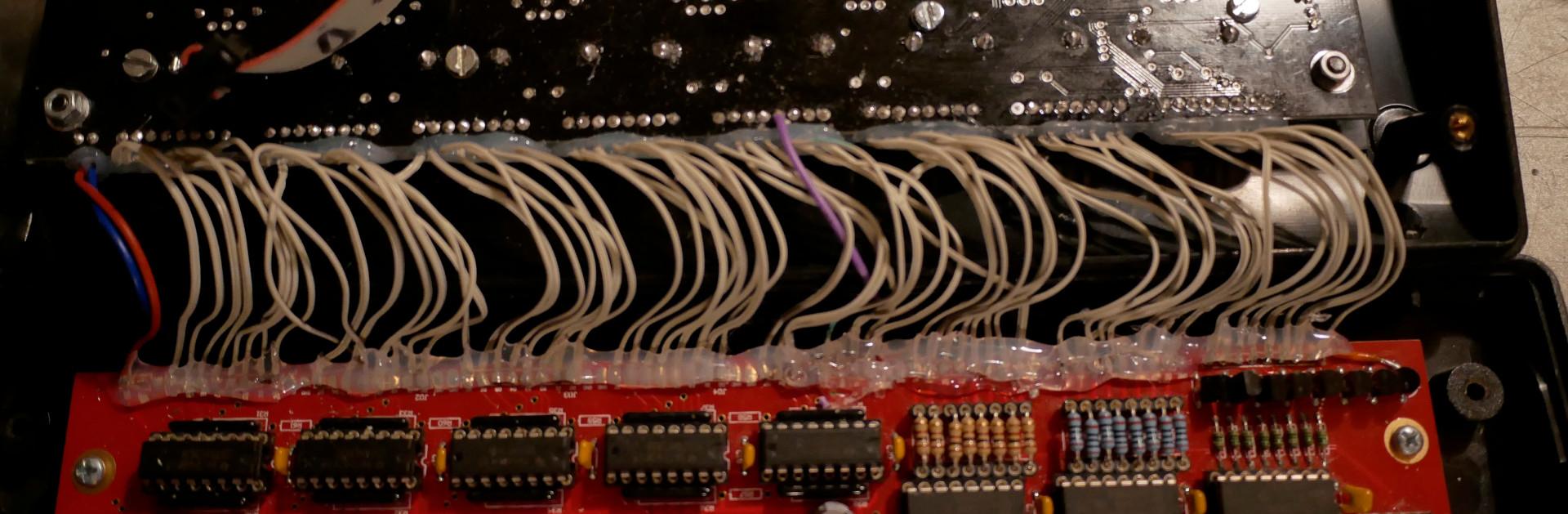
Hey man. It's actually an FR4-Standard PCB. Non aluminium. But seems pretty robust anyway.2 points
-
Thanks for keeping this projects alive I will try to buy one of them next month if its possible again thanks so much for your work Best regards1 point
-
Hello how much will cost the mb6582? and also If you plan to build a sammichFM let me know1 point
-
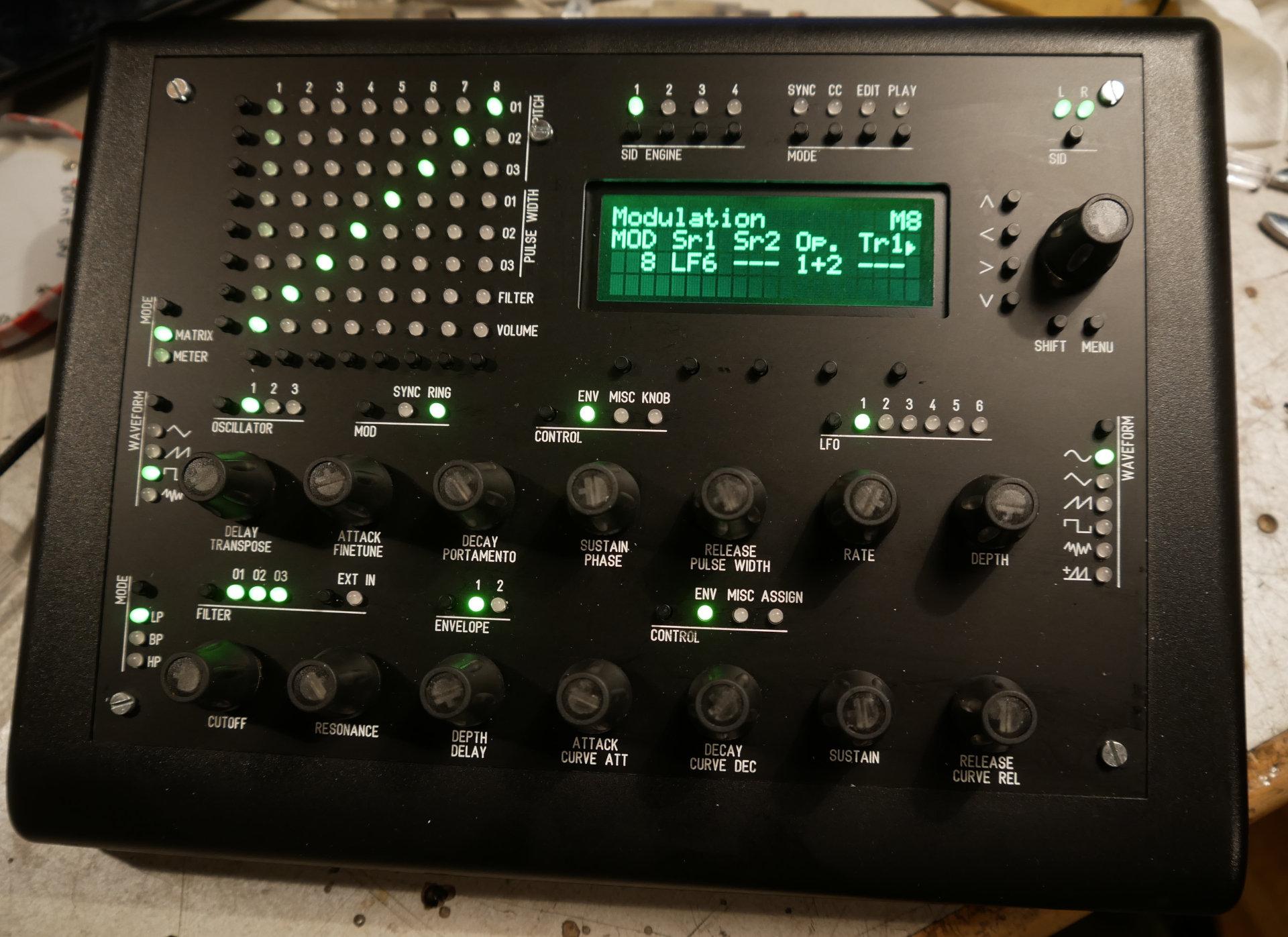
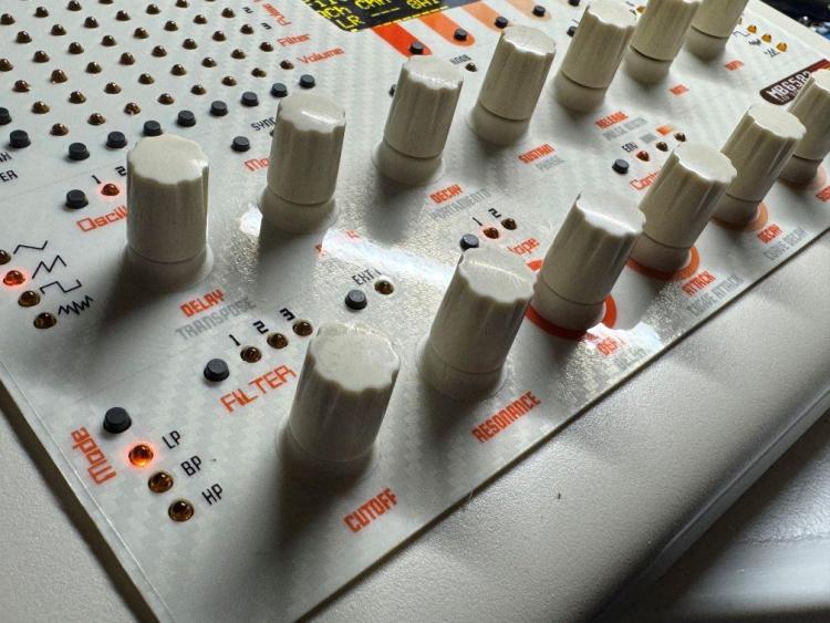
From what I gather from the manual and changelog, this LED indicates whether you have selected a „positive values only“ waveform for the LFO (instead of applying the default workaround by showing waveform LED + Random LED). It does not indicate that the value of the LFO is currently positive.1 point
-
1 point
-
Prompted by a message from freddy, I've attached the project files below. They contain the source and the binaries for the bootloader and the main code. 1.05 is the latest version - there was a fix in the bootloader and the main code. I included some memory in the final hardware design but never got around to doing anything useful with it. I had plans to save one or more demo tunes as MIDI files and perhaps save some settings as profiles for different scenarios - my interests had moved on before that happened. You can find more project info at https://web.archive.org/web/20210206041027/http://www.grapevyne.com/pic.projects/ - the documentation links are all active so you can download the magazine articles and also my original source for the articles (a few errors crept into the magazine article during editing). mistralXG project files.zip mistralBoot.zip1 point
-
To use Studio on newer Ubuntu Desktops you need to install the old libwebkit2gtk-4.0.so.37. To do so create a sources.list file for apt containing the following line: deb http://gb.archive.ubuntu.com/ubuntu jammy main And install the lib. sudo apt update sudo apt install libwebkit2gtk-4.0-dev After this delete the sources.list file. More infos on https://www.weigu.lu/music/midibox_hp_2x2/index.html1 point
-
II replaces the remaining ICs and its working! Woohoo!1 point
-
Reflowed the ttasnsistors on the top side and now I am back to 12 LEDs on. I'm assuming the LEDs shouldn't be on, but otherwise that feels like an improvement as it means I get mattias switch events for 12 of 16. I'm also getting events for depresses on the right 4 encoders although they seem a bit random in the actual event details. I've also replaced IC2, IC3 and T3 based on advice from ChatGPT but that made no difference.1 point
-
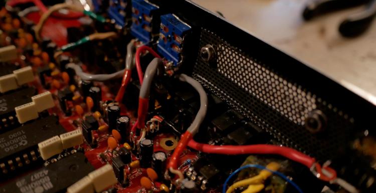
Cool solution, looks great! The skirts for the knobs are a nice touch. One thing I wonder about is if heat would build up here, as the free air space in the case is less and the panel is also an insulator. The SIDs are on another PCB of course.1 point
-
With velocity bars there is more info displayed and the spacing is more uniform. The hyphen/minus as a spacer for natural notes helps to connect them; with spaces it is more confusing. Do you really use those low octaves so often @anonyme-x22? If it bothers you, a workaround is to transpose either on the SEQ or your synth.1 point
-
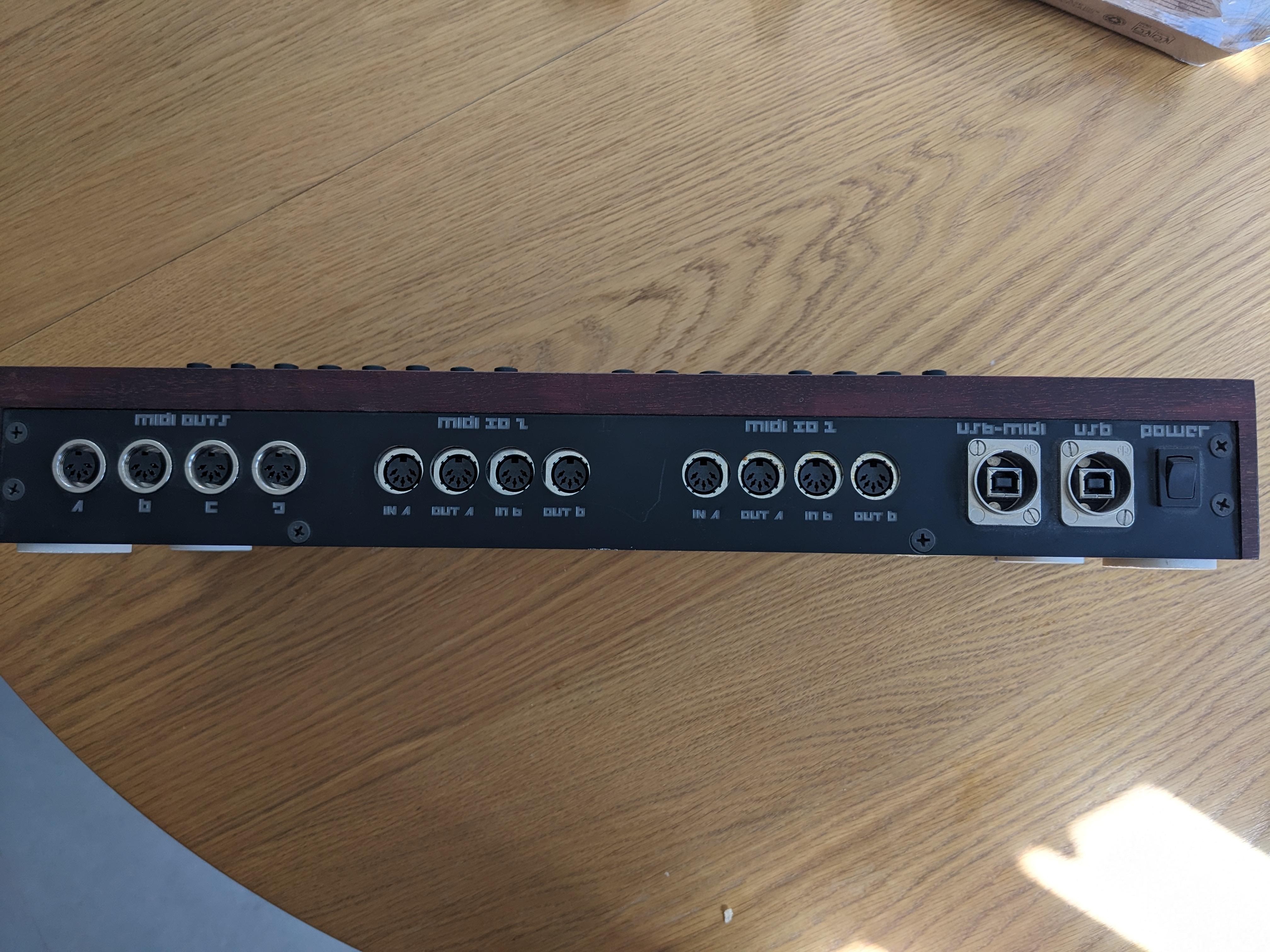
MB-6582 SOLD Selling these as I no longer use them. I assembled the MB-6582 myself. It has 6x 8580 SIDs installed, and could use some TLC: - The encoders occasionally skip counts when adjusting them. I think this is just down to a bad batch so replacing them should fix it - Some of the standoffs that attach the front panel to the CS PCB have come unstuck and need to be reglued The SEQ V4 works perfectly €500 for either unit I am based in Spain
 1 point
 -
Arrived and kicking. Thank u for your service ❤️1 point
-
Confirmed over here, no humanizer being applied to CC’s. I tried with an empty track sending layer A as CC on buss 1, and another track listing to buss 1. The listening track was responding to the cc’s, but humanizer did not effect the CC’s. Then moved the cc to layer B (usually the velocity layer) and still no changing of CC’s sent. steve1 point
-
New top as requested PM me please, or I can send the details as well.

 1 point
 -
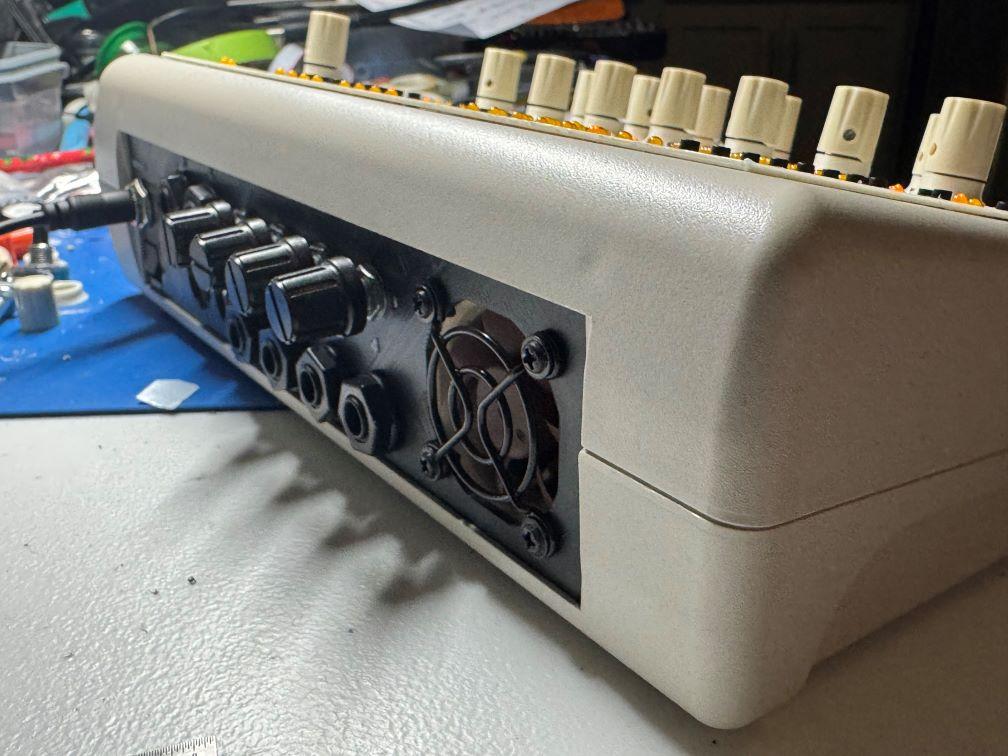
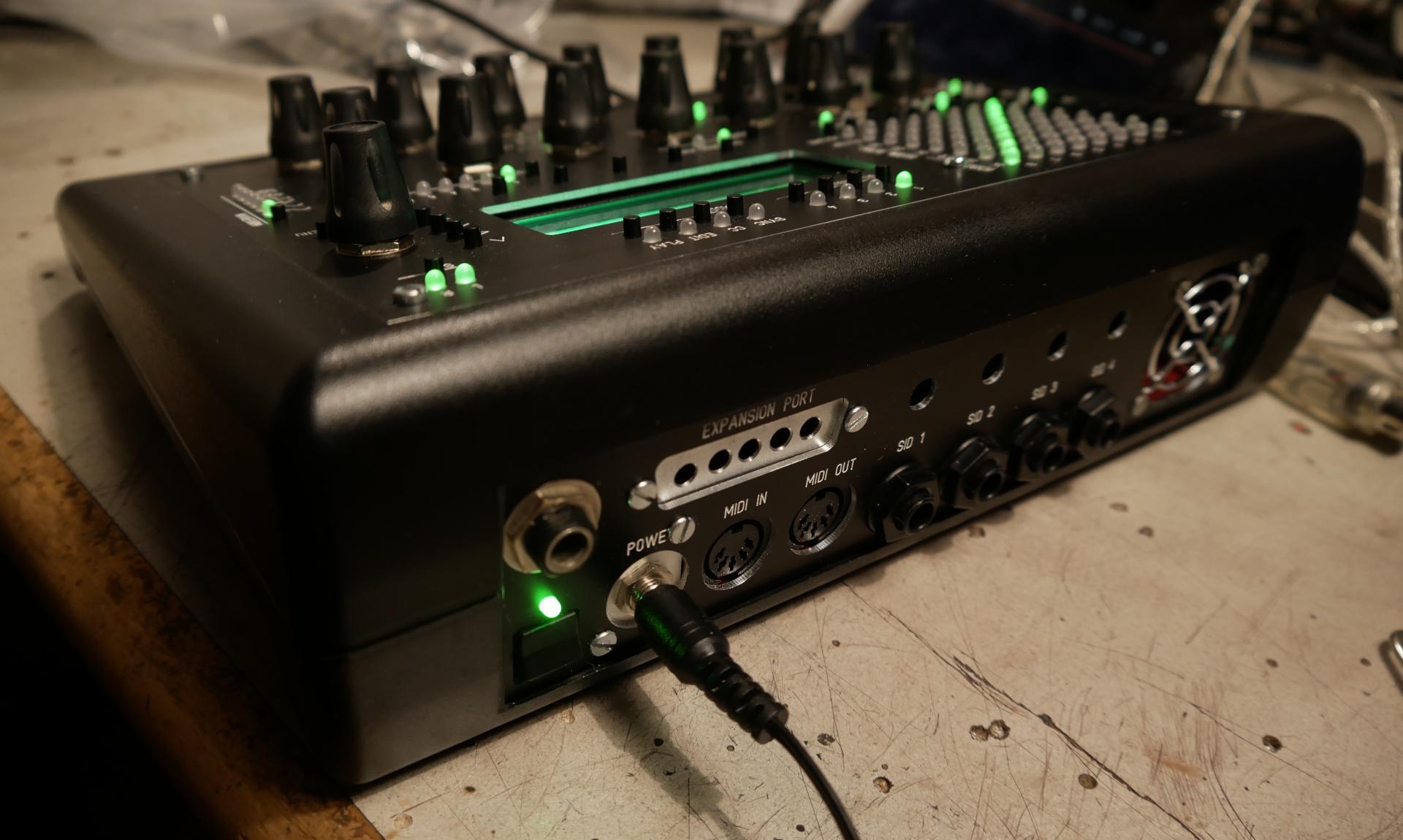
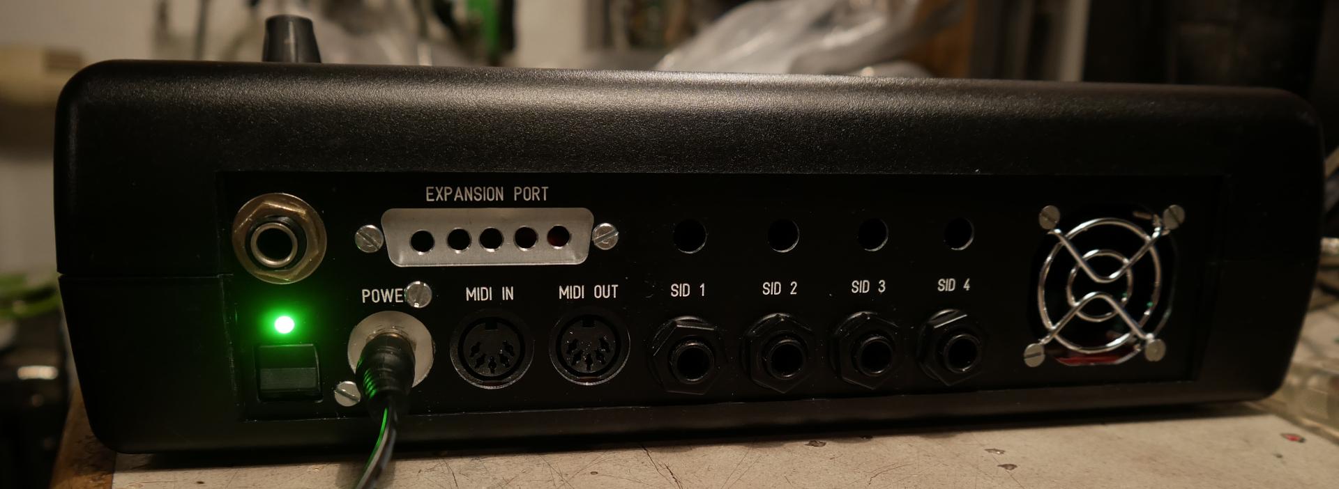
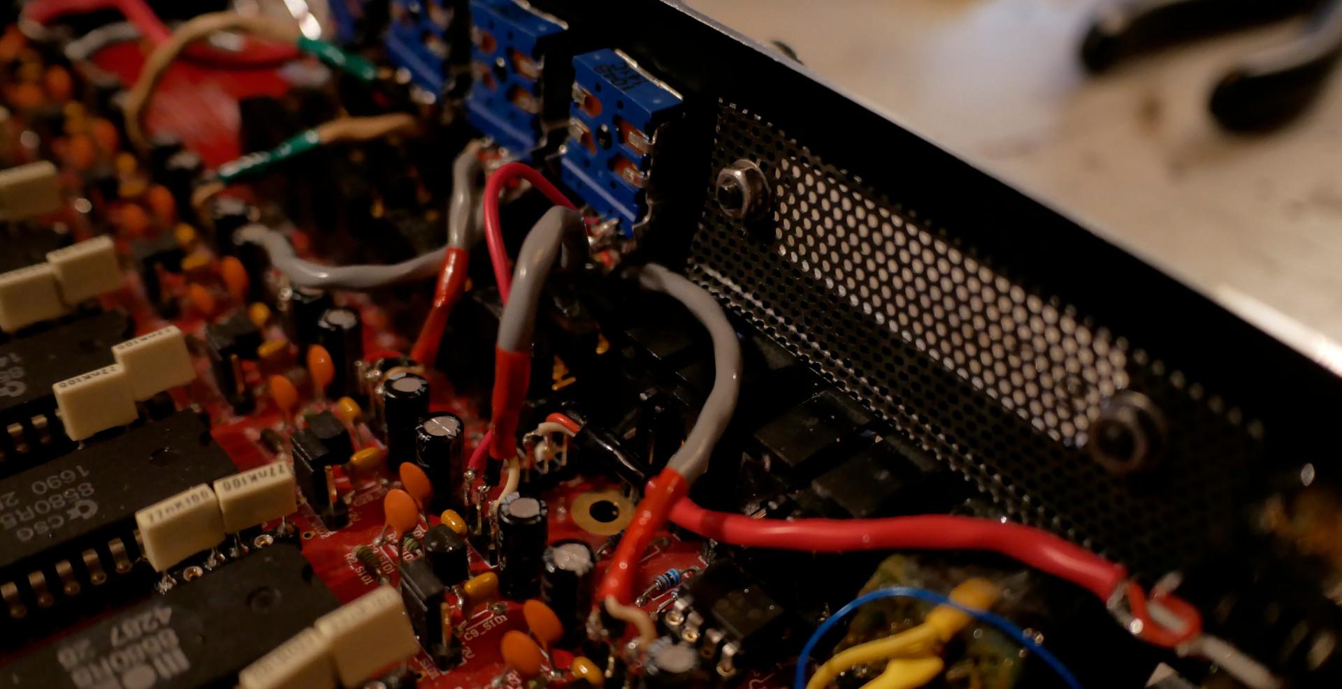
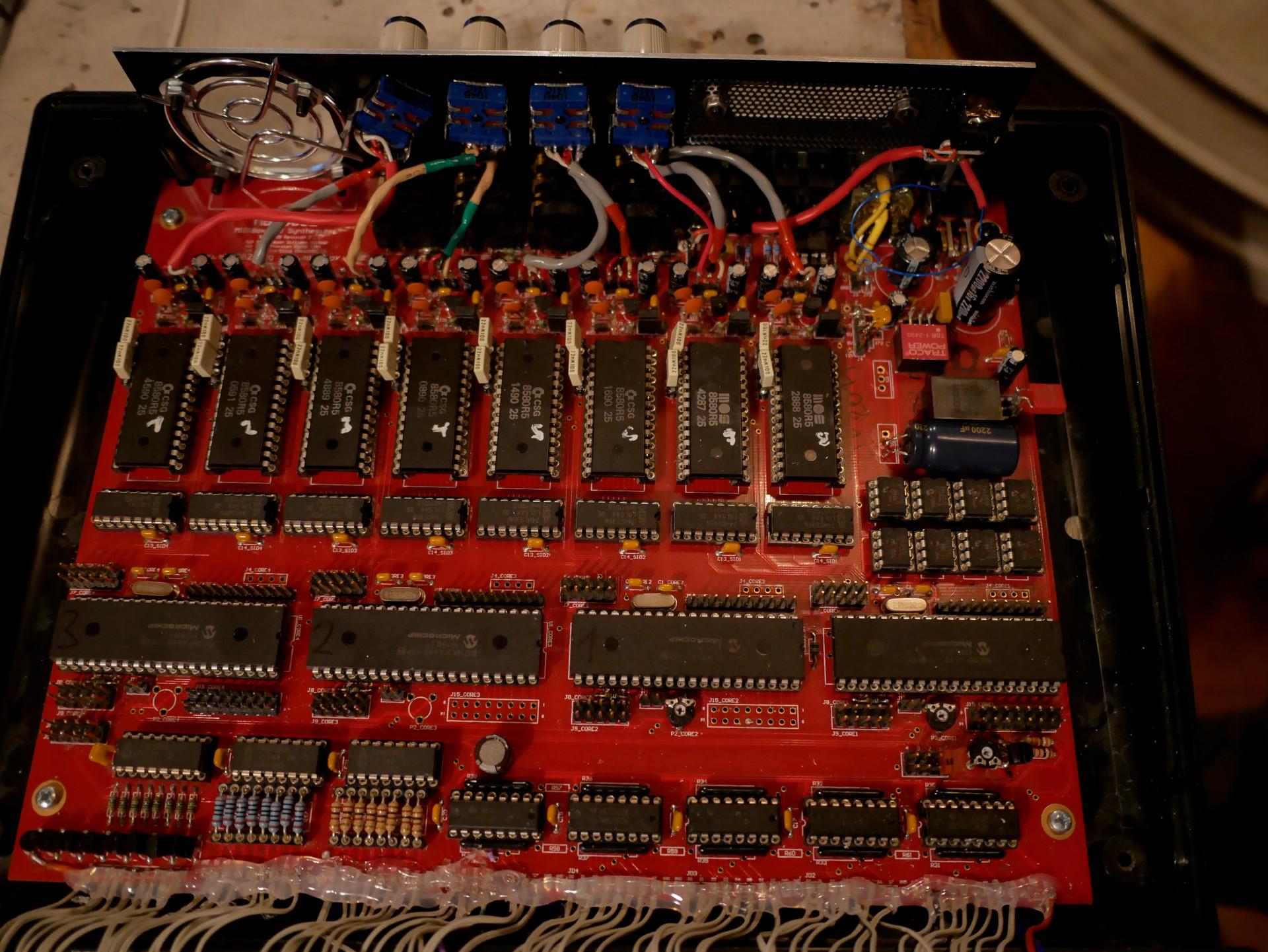
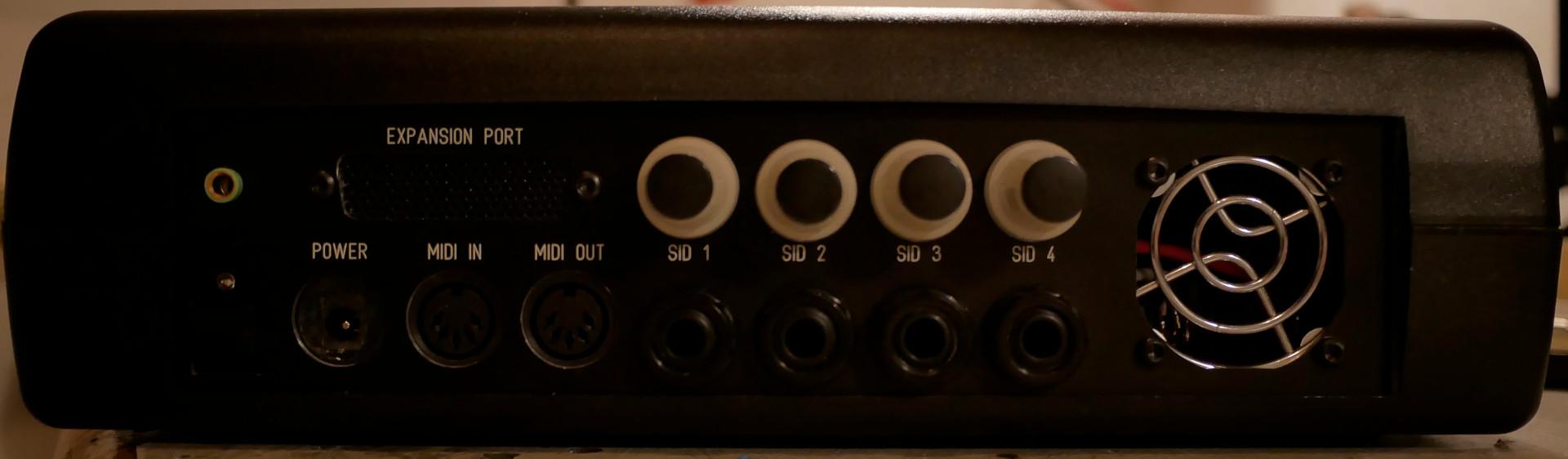
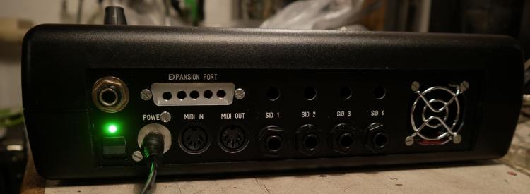
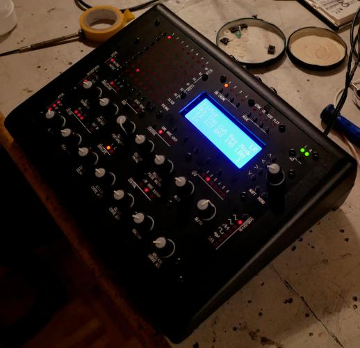
i made a passive design, since the fan which came from mouser, was dead from the beginning... since it is a 6582, it was not going very hot anyway... but i drilled Holes into the pcb under the SID-Sockets, and cut aways some plastic from the socket too. i too drilled some holes in the plastic body under the Main-PCB too, the backside off the SID should be enough to get rid off the hot air...

 1 point
 -
a nother passive SID alive...


 1 point
 -
Thank's for the tip! What I'm looking for is either the fpd file which fits the Heidenreich case or maybe a ready made panel. The fpd file I found in the Wiki seems to be not specifically made for the Heidenreich case. I prever a fpd file which is proven to fit into the Heidenreich case before trying to adapt Wilbas files to the case.1 point
-
If you made your own PCBs using the available schematics, then I think you may be free to sell them to others here, since they're your own derived work. However, you cannot sell the finished and fully assembled sammichSID or MB-6582 synths as commercial product without express permission. Someone else here may want to jump in and correct me if I got that wrong...1 point
-
Hi ssp, I don't remember if labels can be called from a map, but i don't think so. However, i think it is possible to change the display using a .ngr script. Bests Thomas1 point
-
Just a small necro-bump :-) …by now we are roughly 150 people over there with some occasional chatting going on. Feel free to drop by!1 point
-
maybe its the Ripple off the PSU about your PSU - reichelt specs is saying : "Ondulation résiduelle : 80 mVcàc" i guess this is not a 50Hz ripple but HF ripple... --- i guess some small cap (100nf, 10pF) and a big Cap (depends on the load, use for example a 100uF and a 2200uF) on the output off the PSU would reduce that "ripple"... * maybe that caps are not enough and you need some more filtering (coil, resistor, lpf...) but i would start with some caps... the connections in your 2nd picture are not necessery - i guess (dont seeing the whole picture, but i think so...) --- so picture 1 is correct. by the way - its only the last LED that flickers? maybe you have to terminate the DO line on the very last LED off the Chain with a 10K resistor to 5V or Ground. else it could be a software problem, when the software loops thru the LEDs, and when it comes to the last one it jumps to the beginning off the chain... try to programm in the ng code one more LED (which in reality not exists) - so you can be sure that this is not a software bug... - but dont ask me about ng-programming --- no glue about that. - mike.1 point
-
Hi all , Was wondering about opening a KiCAD Section in the wiki? For tutorials , midibox libs etc... where should i put it? regards, JK Edit : A Frontpanel designer section could be useful too ?That's a soft that i think most of us use? Maybe create a "Softwares" Section?1 point
-
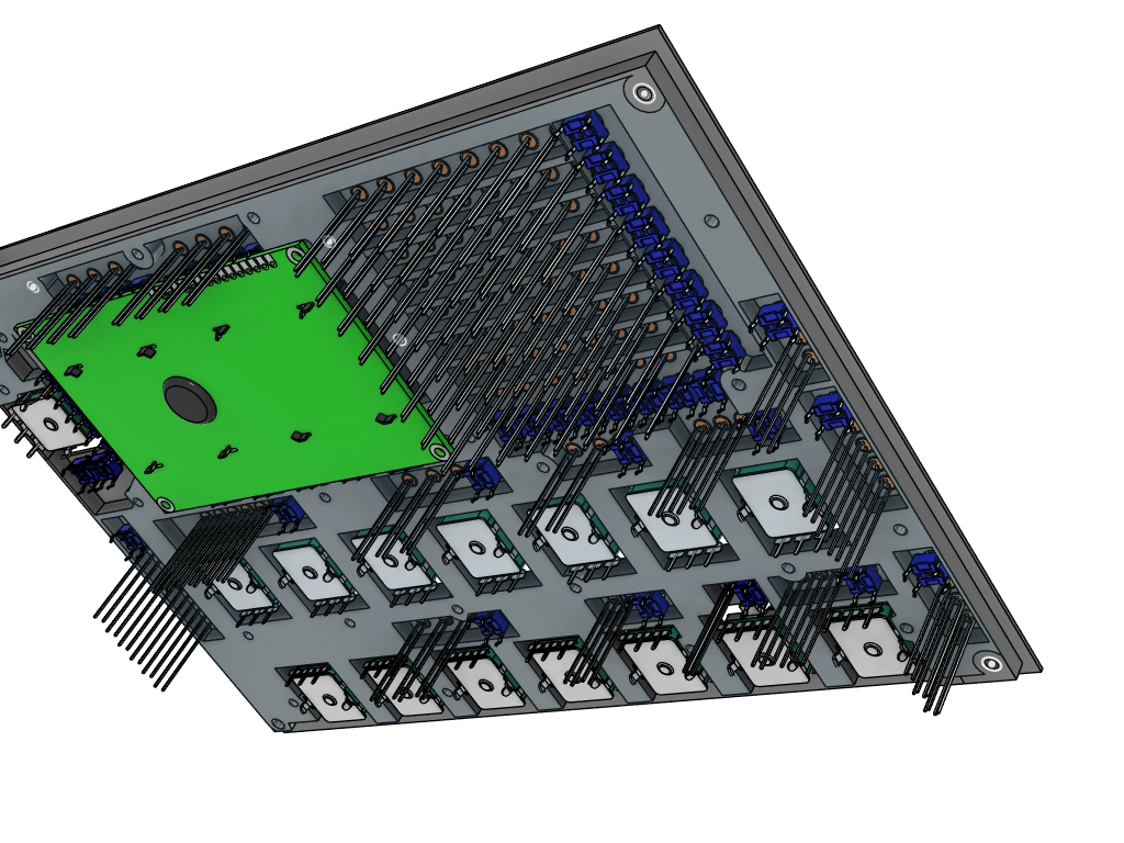
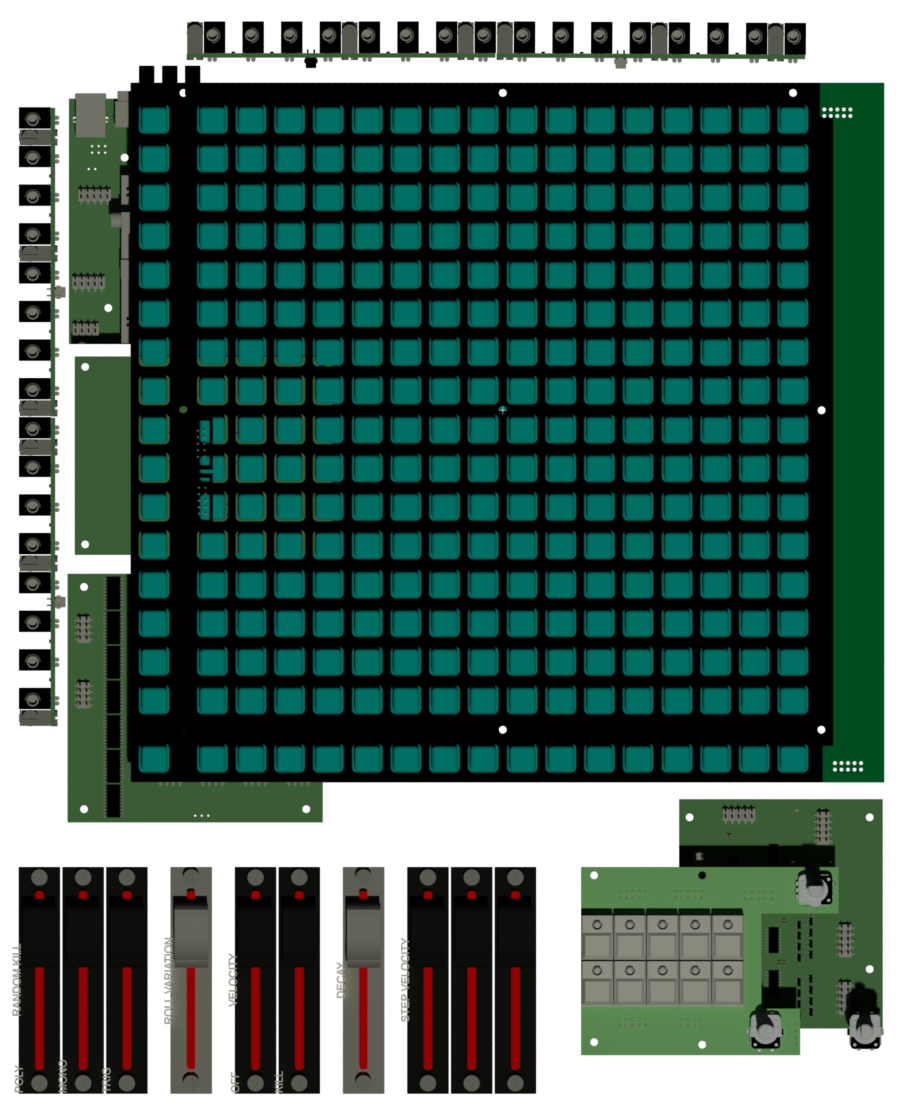
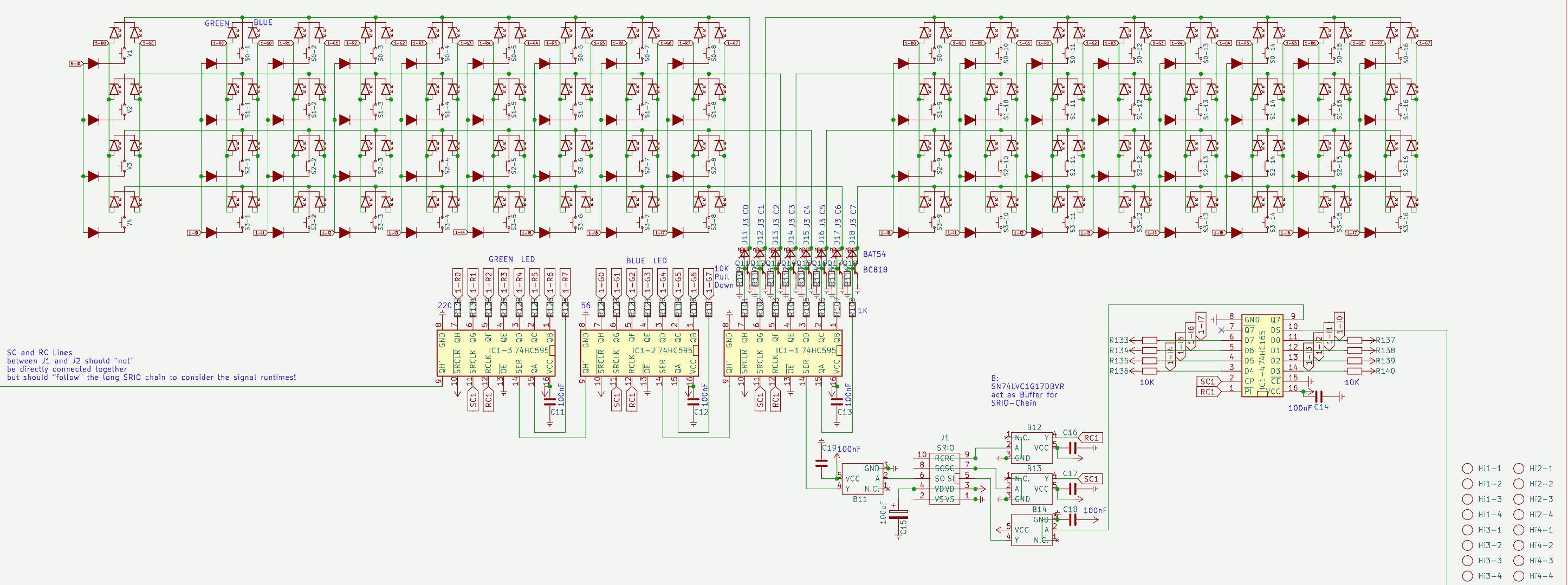
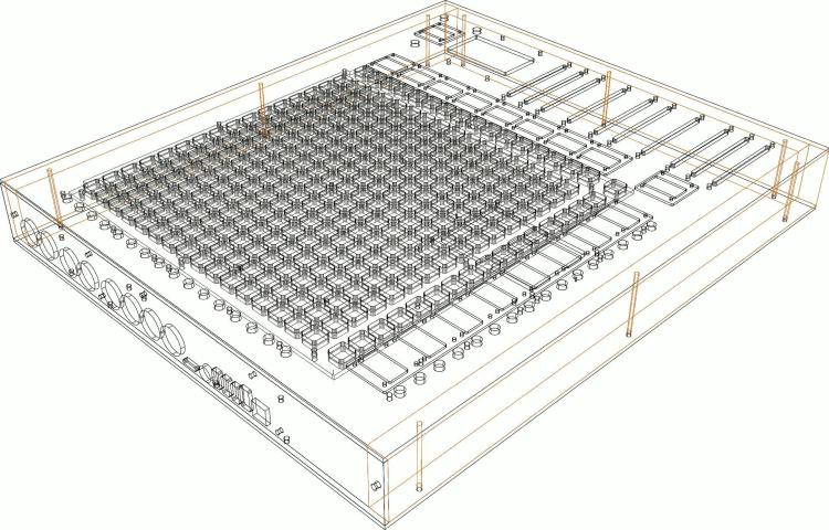
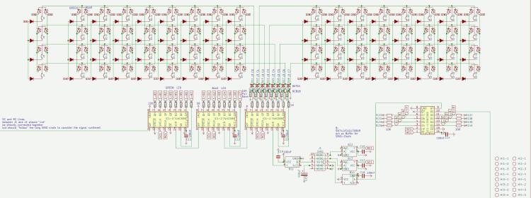
the next generation off Triggermatrix, with insights to shematic, the board-files i will not set free... the Pictures from the Boards are for debugging reasons only. where possible, i made pick and place ready boards - to reduce soldering time... at this point the big BLM16x16 board is not pick and place ready. WIKI: Triggermatrix 5 Display-Driver-SMD BLM16x16-V2 Core 4 Discovery Core 4 Disc - Midi Expansion TM5-codeblock TM5 Din Dout Gates TM5 Gate - Breakoutboards TM5 Gate - In TM5-Housing

 1 point
 -
1 point
-
Hello, I have a rebound problem with the sparkfun pads, do you have an idea how to fix this? Hardware? Software ? Thanks The rest works fine
 1 point
 -
j2/j17 should do the trick yes.1 point
-
Hi Long time I don't play with NG config, but It should be possible with enc_mode=Inc41_Dec3F , combined with fwd to 2 sender and conditional filtering, something like if_equal=0x41 send note A, and if_equal=0x3F send note B ?1 point
-
@ Faderboard 1 & 2 Mounting holes labeling not necessery again. rest is ok. you may could label + and - beside the 2x5 shroudet Pinheaders, so there is no chance someone reverse it in a way... in generell... normally the Nose- says all, but someone could crimp the cable incorrect... so if he controll measure, this is a good hint then for him.1 point
-
maybe by removing the pull-Hi resistor off the HC165 Circuit, and using a Inverter on its inputs for example: https://www.mouser.at/ProductDetail/Nexperia/74HCT1G14GW-Q100H?qs=SKY61BOKKY4Uv%2FaFLc8SsQ%3D%3D https://www.mouser.at/datasheet/2/916/74HC_HCT1G14_Q100-2937184.pdf (just a example maybe there are better parts for this porpuse, and i dont know how hard to solder this one is) that would reverse Lo and Hi, and you could use this bloddy 3 LEDs ( where i think thats not a good idea, the Encoder is expensive - and not really a standard part...) but for that quick idea i would prototype that first (order a inverter, order a Encoder, make wires without pcb) ... specially iff any pull hi or pull low resistors are needet elsewhere, i guess you need a 10K pull-low resistor (to ground) on pin 3 off your Encoder then: HC165 > Inverter > Pull-Low + Pin3 since i have not much time these times, and you have plenty off modules what module i should check next? i just had a look on your 4x2 Enc RGB SW Led ring Rgb render here... and i am not 100% sure that the inbuilt RGB LEDs that enlighten the Encodersshaft dont shine on the LED-Ring and make them hard too read (maybe need some lightshielding)... by the way hard too read, those Alps Knobs are a bit big for that small Ledring - can you still see the LEDs when looking from a angle that is not 100% from top?1 point
-
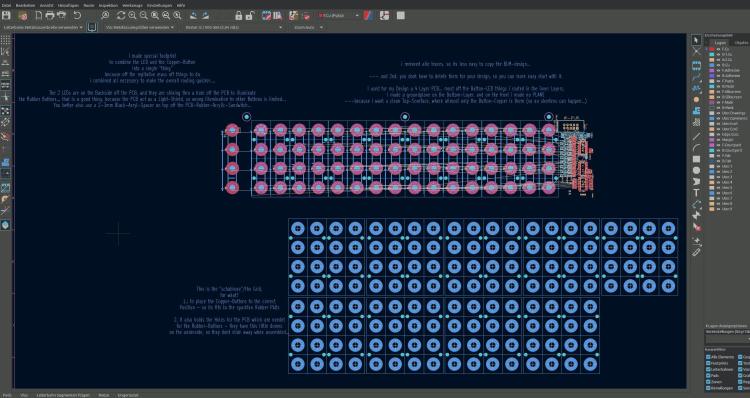
hei i stripped down the BLM-Project (so it cant be cloned with out weeks off routing U B ;) ) BLM-how-to.zip and i wrote some explaination... basicly i made a Grid with a center-cross - so a single button-LED-Fottprint can be placed correct to the Rubber-Button-Grid... you may have to set a a new "zero position off the Kicad Grid" to this crosses when you place the Button-LED-Fottprint on them... this Grid also have the Holes for the PCB which are needet to hold the rubber in Position.. maybe you find a "Flip-Chip" Variant for your RGB-LED... it would be better... you should not place it on the TOP side off the PCB... because it will illuminate the Neightbar-Button-Rubbers... The Hole in the PCB where the LEDs shine thru, act as a Light-Shield... I too have to draw a RGB-LED board (for a other Task, to illuminate a Frontpanel...), since i dont have expierence with that RGB-LEDs... this will take a while... if you found a solution i would copy it from you.... At Kicad 7... didnt know there is a stable out... good to know... will update too (else i cant check your projects)
 1 point
 -
That's absolutely glorious Peter! Nice work (as always!)1 point
-
at RGB-Leds > i dont know, how many you will use? which coremodule you will use? is it eurorackbased > and eurorack powerd? Which RGB-LED you will use - and what is the Voltage it needs? and so on.... i looked into your files.... some notices: @BP: dont connect the mountingholes to ground, or any other potential, best would be to make a keep out-area (sperrfläche) arround it, like i did for example here: http://wiki.midibox.org/lib/exe/fetch.php?w=600&tok=f96292&media=phatline:daw-btn-3d-b.jpg since you can plastic and/or metall standoffs to mount that pcb to the panel, you would need at least 6mm or more keepout-area.... background: you want to avoid groundloops over the frontpanel, and the risk of a electrical shock is less.... The LEDs in the diagram are connected false, the tip off the arrow should always be connected to the ground. (you should turn them 180°) which buttons do you want to use? please check the pinout off them... for me it happend that i did not connect the correct pins, so double check this.... why you made those cuts on the 4 corners? its better to make them rectangular - background: if you panelize the pcb, you have to draw a V-Grove line, the machine can only Grove in 90°, the idea, is to put 2 off this boards on one 100x100 PCB so you can save money on FAB.... way more oversight you have if you use a Groundsymbol... instead off paint Lines to a ground inside your shematic... look into "control" to see what i mean...also it makes it easyier to work with groundplanes, since this needs a NET... @Control: please open this file:Control.zip the same like above, and, you dont need that vias next to PIN 2 off the switches > Pin 2 is a via itself.... - same for Pin 1 off P2, the Problem it did not fill without your Vias: because you dont used a Ground-Net.... Pin1 - which is labeld as VDD (+) was connect to all your buttons and the pot (which is a Encoder)... normaly we connect them to ground..... VSS is ground.... so i exchanged the whole thing.... i dont know iff this is then still correct in your big picture- wiring diagram.... how ever thats the way i would make it - at least iff the Pin-Labels off the IDC Connectors are right... you should put the 4 mounting holes in the shematic, so you dont loose them when updating the PCB Also dont label your Encoder with Pot or RV >>> this is not a Potentiometer... that confused me until i realized this is a Encoder.... also the google-Drive files are a bit corrupt - the footprints where not assigned to the Shematic symbols...... when you save the project and upload it somewhere - zip it inside Kicad with "Projektdaten archivieren" - dont know the french word for it. -please overwork also your BP like/or simular like i did.... @Fader 1/2.... please open this file: Fad_2.zip shematic: also better use GND and VDD Nets.... more oversight! if you dont use a Pin off your IDC-Header (P5), then "x" them out with the blue "x" on the right side off your editor.... For what are those outer Mounting holes? they are too near to the Faders...make the pcb bigger so there is space for a Spacer/standoff, or use only the 4 inner mounting holes... which i think is enough.... again better 90° corners.... fill out your Shematics "Circuit-Field" right down - dont know the englisch or french word for "Plankopf" ... by the way you can design your own "Plankopf", so you dont see there thing like "KiCAD E.D.,A kicad 6.0.10......" keep out for mounting holes again... (see PB) dont make outher planes on VDD(+) ... mostly there can happen problems when mounting the thing to a panels, better use Ground-Planes... When looking on your FAders Footprint, and on the DAtasheet for the RA6020F then i am not sure iff the pinout is correct (the datasheet is bullshit...) but i guess you imported the Symbol and Footprint from mouser or something....then i guess its oky.... also use the design-rule check function (in a shematic and PCB-Editor) i did not looked in the other kicad-projects... but i guess its the same - a bit overwork needet..1 point
-
Yes, absolutely. Please PM me for details, ideally including your location so I can give you a shipping quote if interested.1 point
-
Hello all Selling my midibox sequencer including breakout box. The sequencer is fully functional, from a non-smoking household. Has never been used for live performances, only studio use. The breakout box is a bit obvious DIY but fully functional. You need a free slot in the modular system for the +-12V power supply. Selling price 1350,-€. best regards rbv2 https://www.ebay-kleinanzeigen.de/s-anzeige/midiphy-sequencer-v4-midibox-stepsequencer/2241157248-74-42571 point
-
Yes you usually need a metallized knob to make the touch detection usable !!!1 point
-
Looks very nice and neat .I didnt know you are so busy with things . (Thank you for your support). I was working a lot with max/msp and m4l too. Its a lot of fun , but it takes a lot of time as well :) . Enjoy and keep up this amazing work.1 point
-
So good and inspiring to see what you are creating! Good luck with your further progress, I‘m watching you :-)!1 point
-
could be... you can try to filter out some psu-spikes by soldering a 100nf (maybe add also a 1uF or higher for too more stabilize the psu as addition) cap between + and - on the potis legs (most off the time these are the outer 2 legs off the trio)1 point
-
look into ng documentation if there can be set a offset for the middle position so it stays on a position... because pots directly to the core is always a bit random... better use for example: http://www.ucapps.de/mbhp_ainser8.html then you have less random values also check the quality off PSU...off course a faulty pot can be the reason too1 point
-
@ cherry: the switch itself you can get already from eg https://www.reichelt.de/tastaturzubehoer-c8099.html?ACTION=2&GROUPID=8099&SEARCH=*&START=16&OFFSET=16&CCOUNTRY=445&LANGUAGE=de&r=1&SID=967792150a00d890464504461a66ae529d97182e528c945af4544 caps: amazon, alibaba,.maybe.some thing like that: https://www.amazon.com/dp/B00FYO8EDC/ref=mp_s_a_1_5?keywords=flat%2Bkeycaps&qid=1675511770&sr=8-5&th=1&psc=1 https://www.cherrymx.de/en/dev.html the low profile is maybe interesting....1 point
-
@poti; if the shaft's center is in the end on the same position - so same frontpanel holes can be used.... and: when soldering the thing: first mount the pcbs with loose potis on the frontpanel then solder it (and document this in the "how too build"... @ - : use thermal destress traces (cant remember the kicad word) when using groundplanes, so you can desolder the the poti much easier.1 point
-
control hardware yes, if it is well documentadet on the wiki (shematic, board screenshot) I too work with kicad since decades... and very sucessfull now with my actual projects - i was wondering but i planed it in kicad, and most off the boards where working 100% out off the Box (pick and place JLCPCB), ok i had a design fault on one, but that was solved with a wire-done. actual projects http://wiki.midibox.org/doku.php?id=triggermatrix5 http://wiki.midibox.org/doku.php?id=daw-ableton http://wiki.midibox.org/doku.php?id=openpad software: cant help, write my own Mios-based code, havent look into MidiboxNG - since it is a script, for me more easy to write it directly in C, (need to understand all, else i understand/learn nothing...) - so no help from this side had good expierences with jlcpcb... also with the Pick and Place service FrontPanels: maybe cheap CNC-Laser-Cutting from pcbway? https://www.pcbway.com/rapid-prototyping/CNC-machining/CNC-Laser-Cutting-Services.html suggestions? Maybe use Eurorackformat, so it can be used outside of your box too? suggestion, where usefull (wo sinnvoll) use J89 Serial Chain directly onboard (like encoder with ledring boards) to reduce wireing - a simple button board dont needs that of course.... *** if you go the Serial Chain way, then buffer the Serial chain on each module to keep the digital Signal Quality intact (very necessery) *** buffer: search for SN74LVC1G17DBVR in this shematic: http://wiki.midibox.org/lib/exe/fetch.php?media=phatline:blm16x16-shematic.pdf maybe use pick and place ready smd technologoy like i did: that makes it smaller, and less to solder, less to debug, the plastic packages stays in china, more economical special when ordering more pcbs, by that of course a module should fit all the boxes (a exotic 1 man needs it module 10times fabricated is 9 too much...) i think i dont have to say, that you should choose "Basic" Parts, and not "extendet parts" on JLCPCB, - off course on most modules you have at least one or two extendeet parts... but for example a DINX4 or DOUTX4 can be made with basic parts only... but when you also want to pick and place all the pin headers - these are extendet parts, how ever ... you may look on my last modules a bit http://wiki.midibox.org/doku.php?id=tm5-dindoutgate http://wiki.midibox.org/doku.php?id=doutx2dinx1 if you use long cables to your Displays + u use more displays then one - on the modules, use a display driver (no more walking lines) http://wiki.midibox.org/doku.php?id=displaydriver-smd what else? if you make ground or other PCB-Planes, then setup kicad that it make 1-2mm space arround solderpoints - else the Soldering Man could make shorts, or electrocemical oxidations or solder flux-low-residance could make there some problems (after years), special when the Solderstop-Pain is scratched a bit... ... and so on... PS i hate this wooble feeling off this LeMec Buttons (the last board you posted) - these Buttons are not good (for my taste) I love to work with this ones: https://www.reichelt.de/at/de/eingabetaster-schaltspannung-24v-fuer-led-sw-dtl-2-sw-p7248.html?&trstct=pos_0&nbc=1 they are expensive, but they last decades (in use, and also if you order 300 off them and let them lye arround, after 15 years they still work) They have good CLICK, like a mechanical Keyboard. your leMec Buttons are like a mixture off Rubberdome and "i have to touch this buttons into one direction X=0 Y=0 else it want switch" or you could use: https://www.midiphy.com/en/shop-details/140/4/5pcs-matias-quiet-click-tactile-switch- they are cheap but big... (aka take away a lot of Frontpanel space) or maybe you use cherry switches or simulars.... they are all 1000% better then this leMecs... ( you notice i hate them)1 point
-
this will take a while - look into the forum in 5 weeks or so. i need the PCB to make a new version off Triggermatrix (http://wiki.midibox.org/doku.php?id=triggermatrix4) the Frontpanel is not a generic MatrixController thing - it has 17 Displays, 8 Faders, some rotarys and buttons, the Software for this is not a normal Midicontroller-code (aka Midibox NG) - its my own creation a sequencer based on MIOS. - but if i not make a shematic mistake, the pcb should be usable like the orginal BLM16*16+X in other Midibox Projects.1 point
-
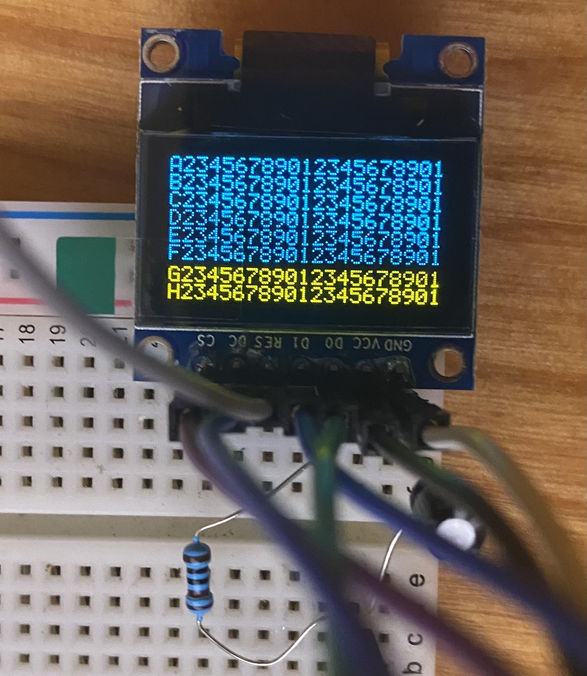
Oh, wow, I totally missed that! Thank you!!! I wasted an entire day rummaging around and didn't manage to see that :) Just in case others run across this: You want 4SPI configuration, not IIC like I have in the pic. The number of screens you have must match the configuration you set in the bootloader, otherwise you get noise, and won't be able to write to all the lines/columns Also easy to miss, but for the 1306 RES connection, you need to wire it up like this (again, connections on your 1306 PCB): GND -> 10uf cap -> 1k resistor -> VCC. Once done, RES will be tied to where the cap and resistor meet (like this) It wasn't clear to me how to actually use the bootloader for the STMF4 board, but it's essentially: Plugin your board as you normally do Open MIOS Studio Click Browse and choose the mios32_bootloader app (download here) Click Start. If it won't complete, try unpluging/pluging the board and trying again Unplug/plugin the board In the MIDI IN and MIDI OUT sections whatever app you had prior to all of this might be listed, but it doesn't actually exist (and it shouldn't). That's why you now see the error "No response...". The new app, MIOS32, took its place and you need to refresh to see it. Click Application -> Rescan MIDI Devices Click Understood in the pop-up (this will make your old app disappear, and the MIOS32 app show up) Change MIDI IN and MIDI OUT to MIOS32 Enter these one by one into the input box: (send a command to MIOS32 application). Keep in mind lcd_num_x must match the number you have chained: set lcd_type GLCD_SSD1306 set lcd_num_x 1 set lcd_num_y 1 set lcd_width 128 set lcd_height 64 store Yah. Bootloader is done. Time to restore your app in MIOS Studio: Click Browse and choose whatever app you want, like midibox_ng Click Start. Like the bootloader, if it won't complete, try unpluging/pluging the board and trying again Unplug/plugin the board Now for some test display data. Lets set some values for your SSD1306 OLED's in MIOS Studio: Click on Tools -> MIOS32 File Browser Click Create File Create some name like LCD.NGC Click Update Click on the file you just created Click Edit Text and add the following test example: RESET_HW LCD "%C" LCD "@(1:1:1)A23456789012345678901234567890" LCD "@(1:1:2)B23456789012345678901234567890" LCD "@(1:1:3)C23456789012345678901234567890" LCD "@(1:1:4)D23456789012345678901234567890" LCD "@(1:1:5)E23456789012345678901234567890" LCD "@(1:1:6)F23456789012345678901234567890" LCD "@(1:1:7)G23456789012345678901234567890" LCD "@(1:1:8)H23456789012345678901234567890" Click Save You should now have 8 rows and 21 columns of text. If you need to flip it 180 degrees, you can redo the steps above and add set lcd_type GLCD_SSD1306_ROTATED before you store.
 1 point
 -
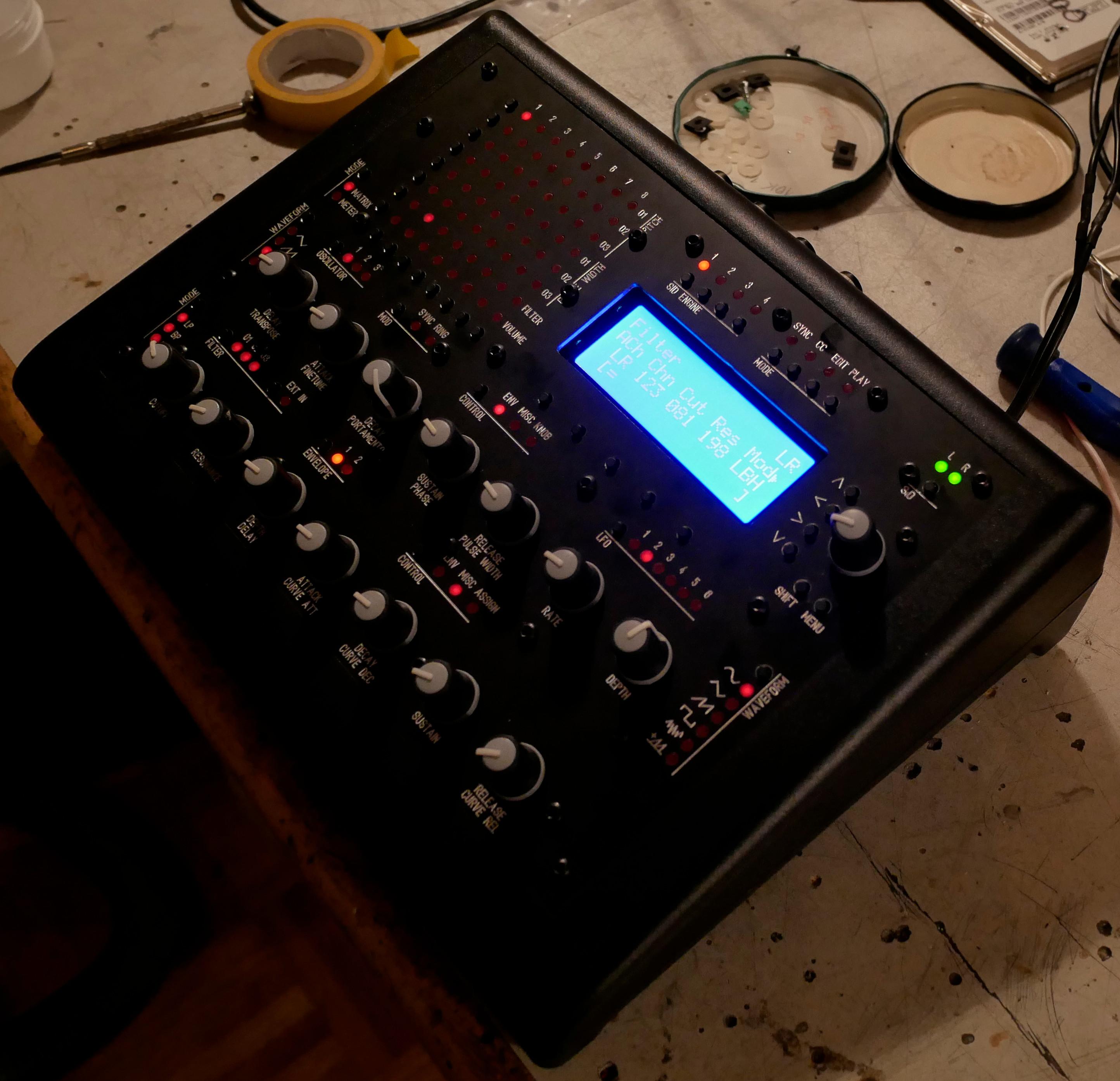
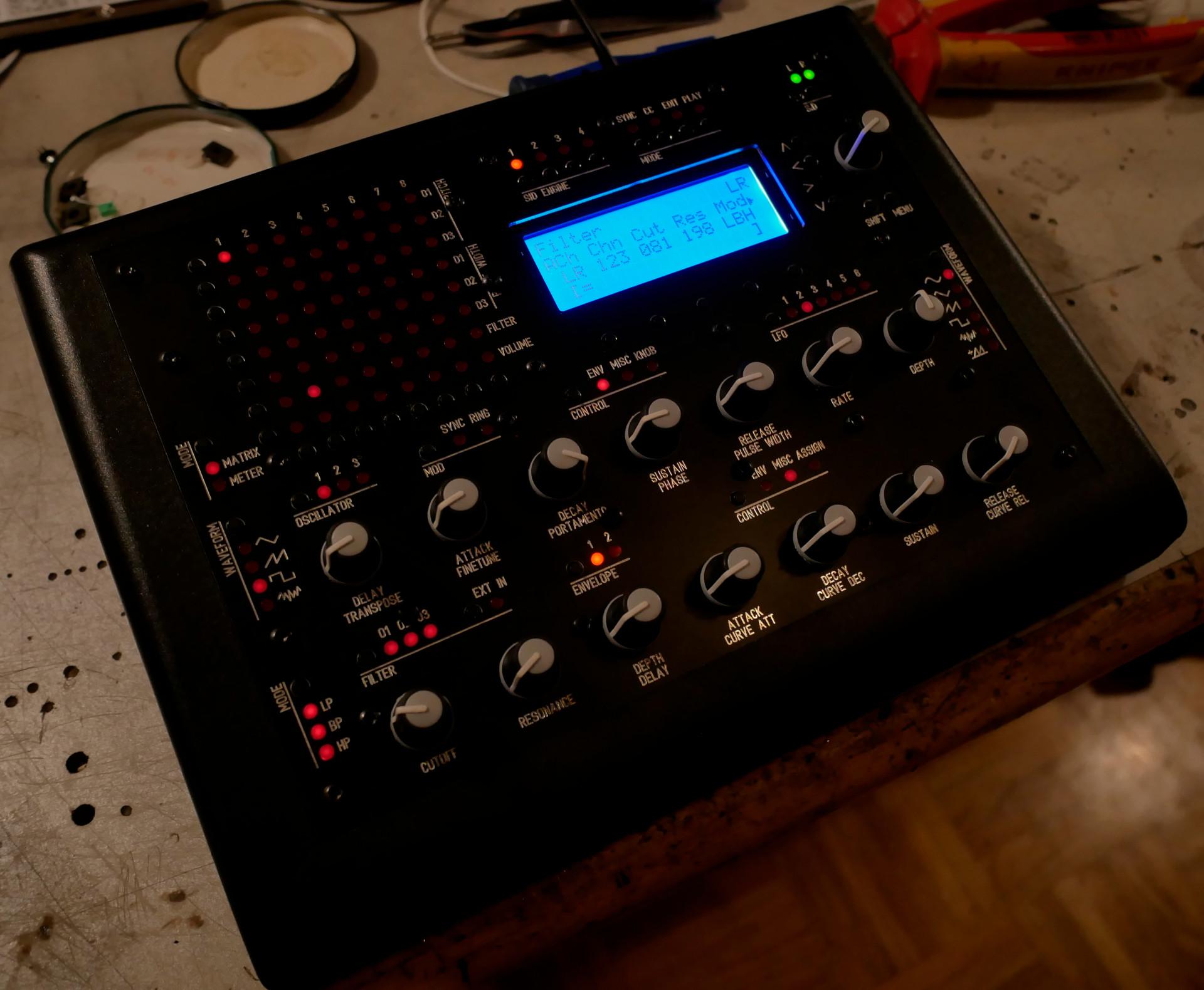
Hi Therezin, I mounted the monitor upside-down because of the viewing angle. This specific monitor has been designed to be looked at from above. It's actually pretty good from around 10° to 90°, but from 95° to 180°, the visibility is very bad. Therefore i had to reverse it so when i seat behind my desk, i'm in the good range. Let me know if this explanation is not clear enough, it's pretty hard to describe in a foreign language. Thomas1 point
-
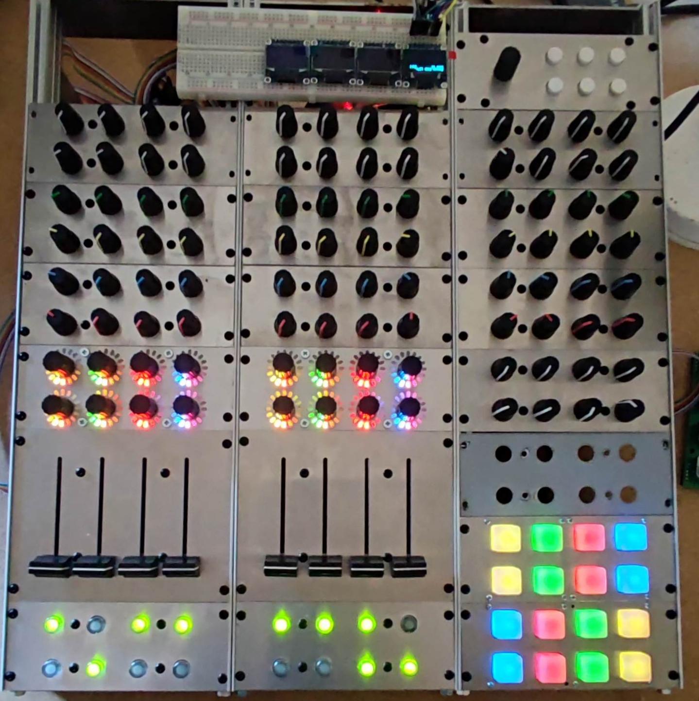
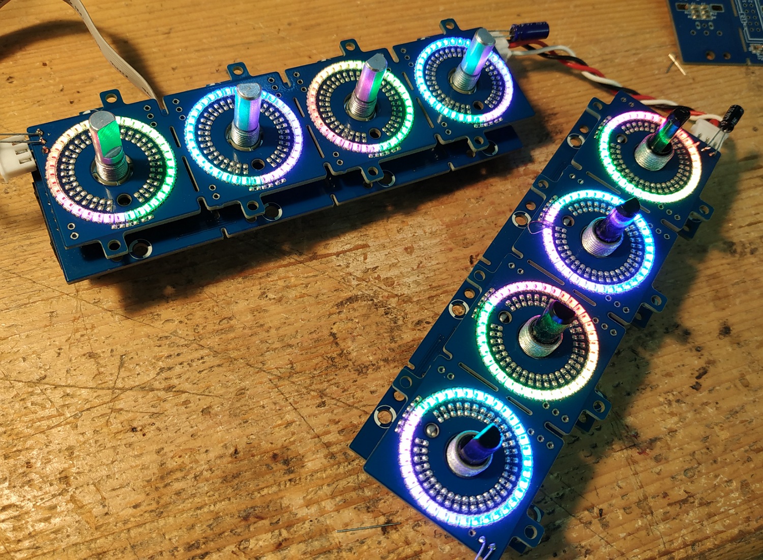
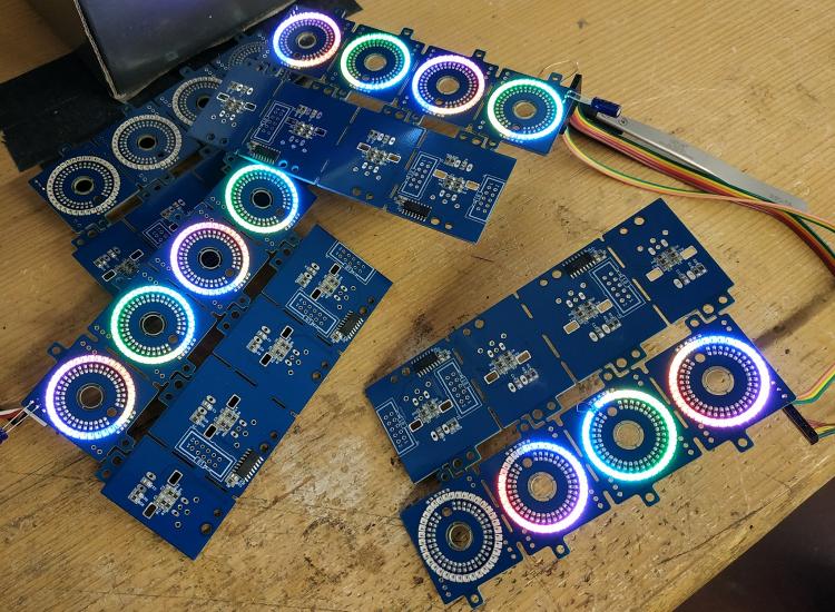
Hey people, thanks to @TK.! It's working great. Anyway I had still some flickering on the LEDs. As I stated above I left away the caps ... and this was the reason. I know have added a 10uF on the input and on the output-connector of the LED-rings and the flickering is completely eliminated! Great!! So, one core can handle a total of 10 LED (10*36=360) rings....
 1 point
 -
Good. Maybe someone need good midi samples for beatmaking www.lucidsamples.com/edm-samples-packs/278-edm-magical-midis-vol-3.html and https://www.loopmasters.com/search?q=midi1 point
-
for those who don't find a sd card socket for the core stm32F4. you could use micro SD card and the ADAPTATOR will be the socket like:http://www.ucapps.de/mbhp_sdcard.html first solder unused component legs to the adaptator: solder to the core but leave some space to the board for avoid short (be carefull pinning): you could fix it (glue) if you want (not done for me legs are sufficiant) et voila!1 point