Leaderboard


Popular Content
Showing content with the highest reputation since 10/02/2022 in all areas
-
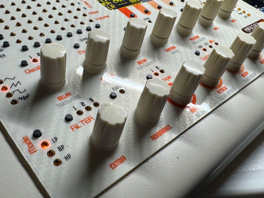
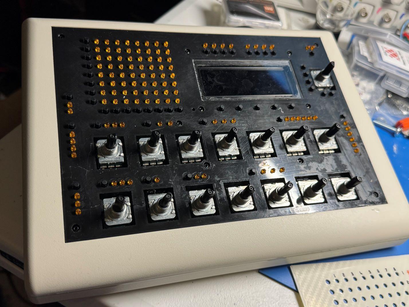
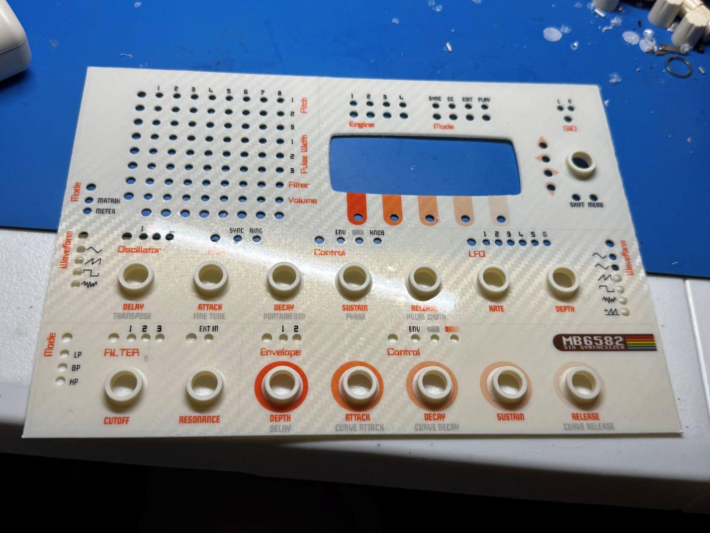
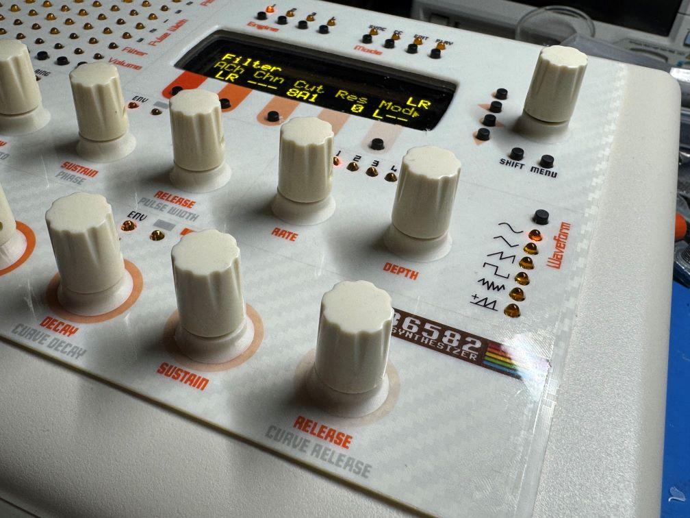
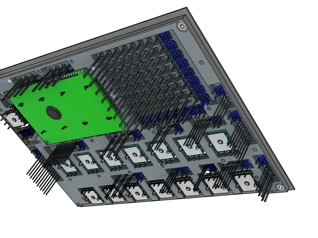
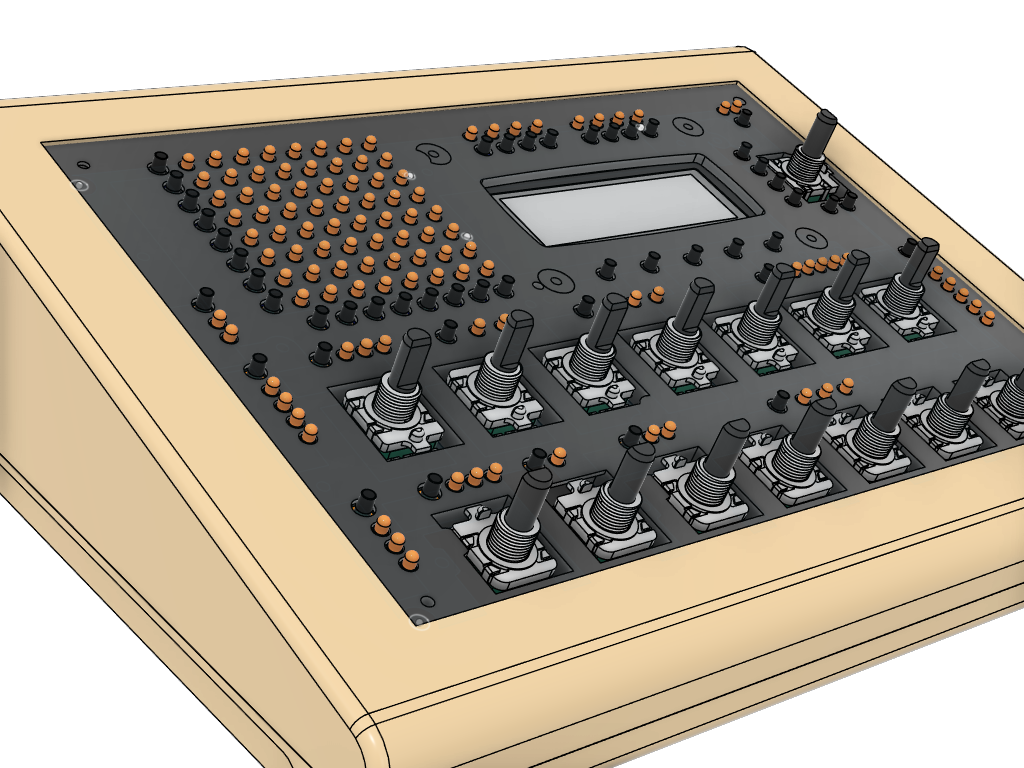
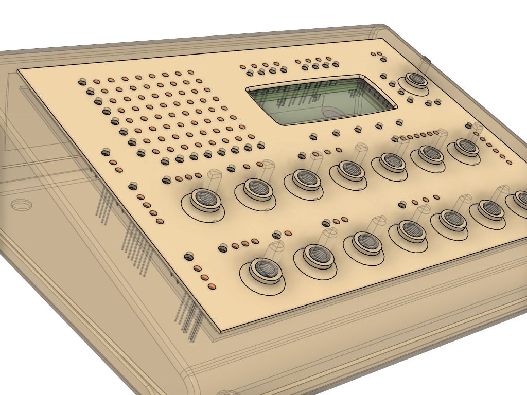
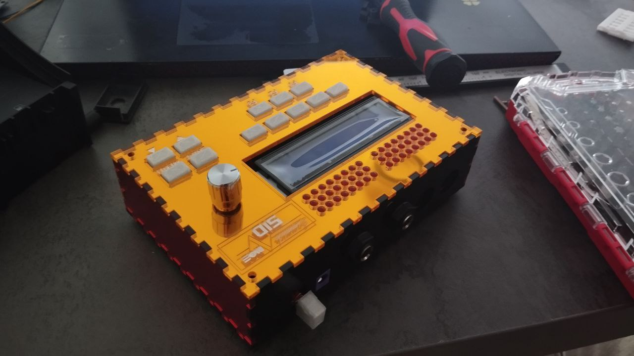
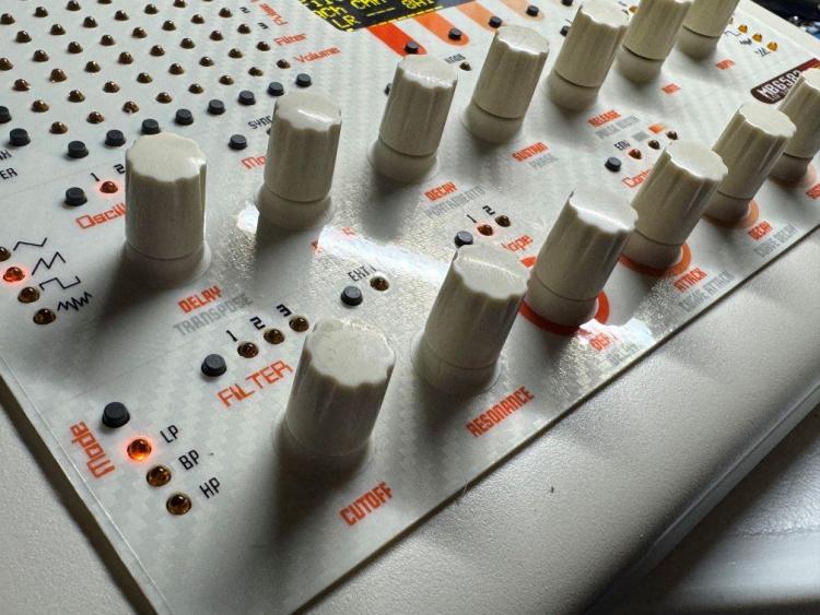
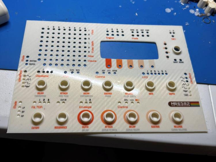
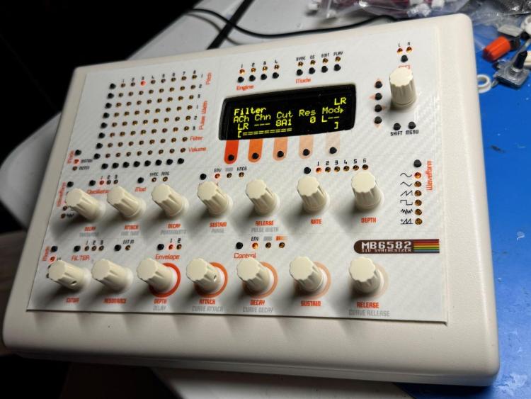
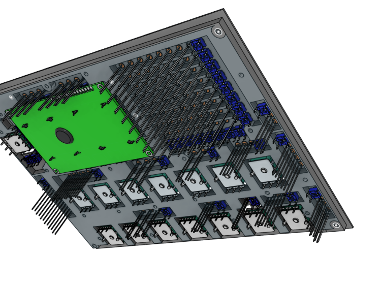
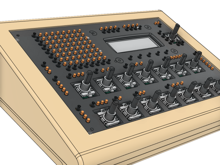
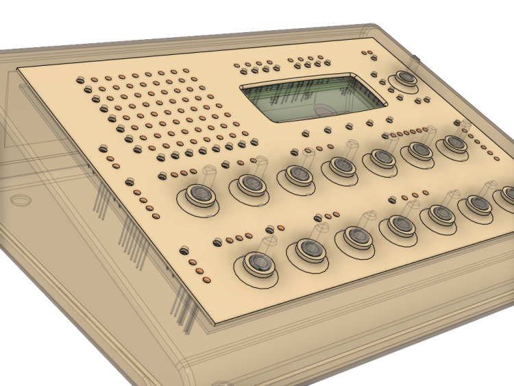
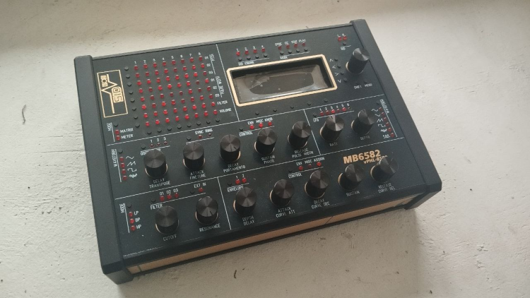
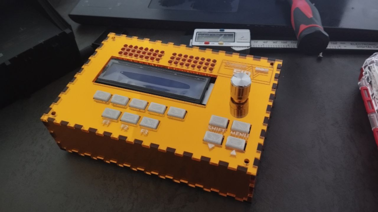
Hey everyone, just wanted to share my latest build since I'm sure there are some 3D printing enthusiasts here like myself. I bought the parts for an MB6582 about 5 years ago, if you remember Meeblip was selling those 8580 SID chips and I picked up 8 of them, and then put everything into a box in a closet . 3D printing has come a very long way since the original MB6582 was created by Wilba. I read that the JB Weld solution may or may not be holding up great after all this time. Also, I wanted to use a Newhaven OLED which is much thinner than the original LCD. I thought there must be a solution to lower the gap distance so why not create some type of spacer for between the front panel and the PCB? I designed all parts in Fusion360. The PCB screws directly into the spacer using M2.5 nuts/screws and plastic screws. The top of it has a flange that rests in the panel groove for the PT-10. Total spacer height is 5.7mm which is the height of the base of the encoders. The front panel is another 1.25mm. Everything is printed out of ASA, which is very strong and heat resistant. I designed the panel graphics in Inkscape and printed on translucent vinyl. I used Davies knobs with small printed skirts to cover up the threads of the encoders since they were exposed. I do not have a vinyl autocutter but I do have an exacto and lots of patience Overall tried going with a 80s beige computer look. A build plate for my printer created the carbon fiber effect on the panel. I'm happy to share the 3D files if anyone could use them.


 3 points
 -
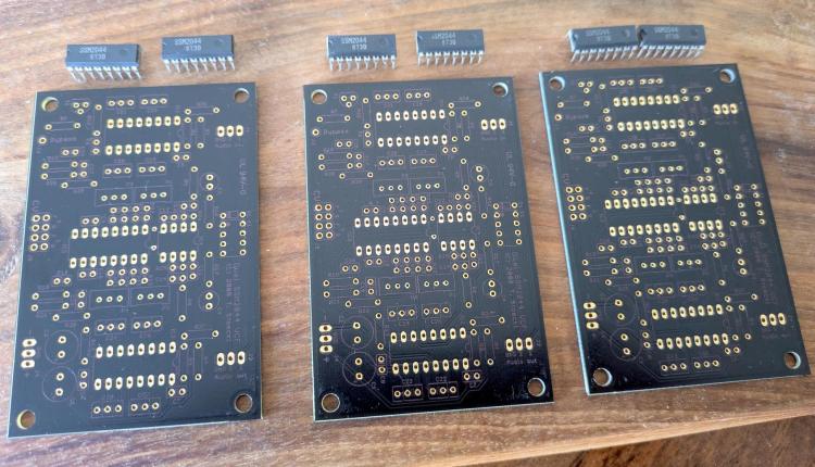
Hey man. It's actually an FR4-Standard PCB. Non aluminium. But seems pretty robust anyway.2 points
-
2 points
-
Hi, I might have what you're looking for. Would you be interested with original 2044 chips too? edit: found, PCBs from Seppoman and chips from Wilba
 1 point
 -
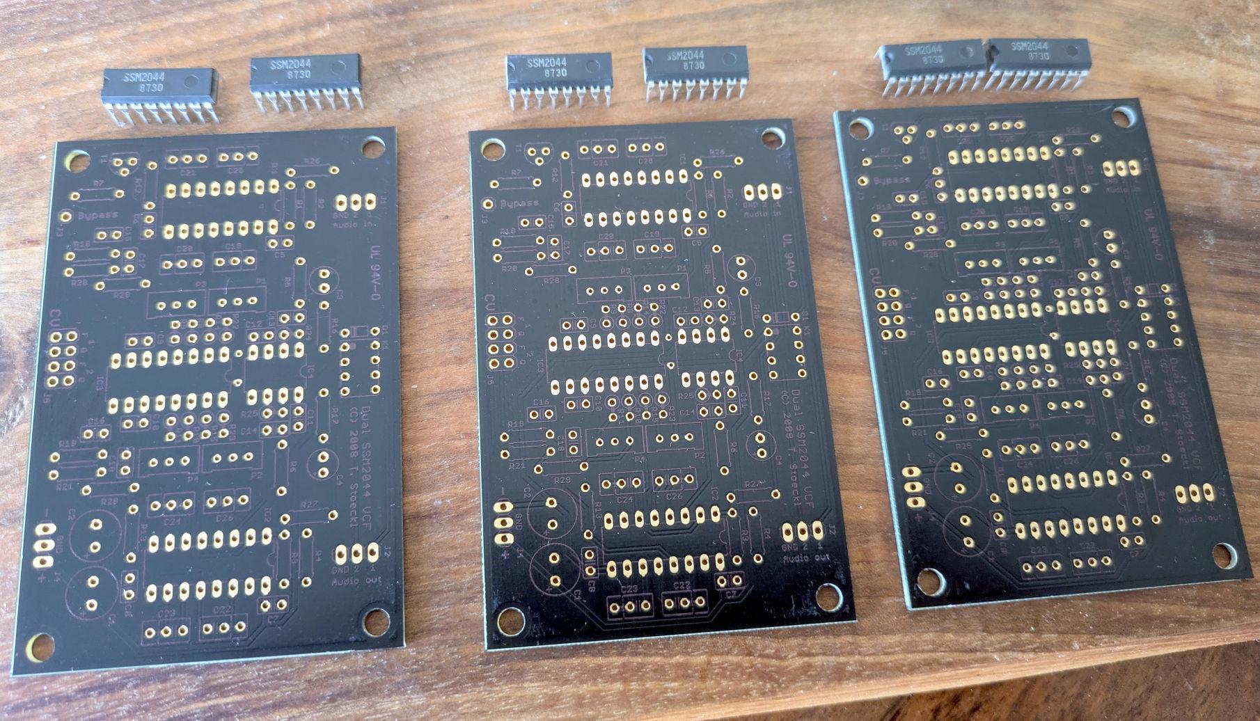
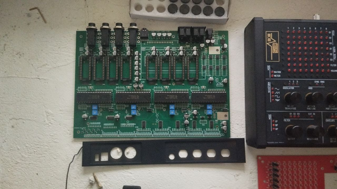
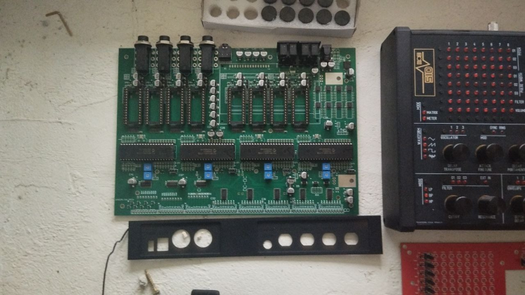
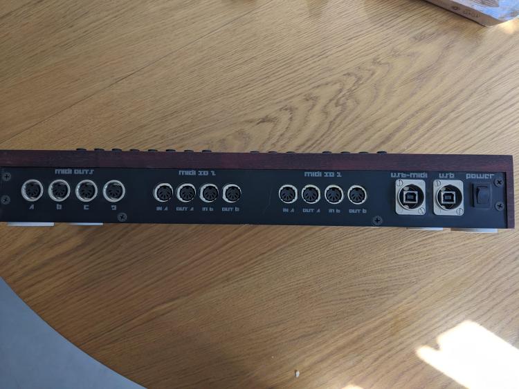
Hello everyone! Over the past few months, I’ve engineered a brand-new MB6582-style synthesizer, deeply inspired by the original Midibox MB6582 but redesigned completely from scratch for improved reliability, easier assembly, and modern component availability. Key new features: Premium ENIG front panel PCB - durable, professional finish 4 PIC cores onboard - full MB6582-compatible architecture Factory-manufactured PCB set, including the front panel Supports ArmSID, Kung Fu SID, or original 6581/6582/8580 chips Clean internal layout, solid build, and high-quality components Prices: Base unit: 420 EUR + shipping With Kung Fu SID set: 499 EUR ArmSID pricing available upon request. Availability: The license allows producing 10 units, so I’m offering 9 units for sale. 1 unit is in stock right now Additional units can be assembled in 3-4 weeks If I receive permission to sell more broadly, I plan to lower the price and release all design files as open source I will make a separate thread in Latest News or somewhere else Photos PCBs and components:


 1 point
 -
From the album: S.M.A.K.
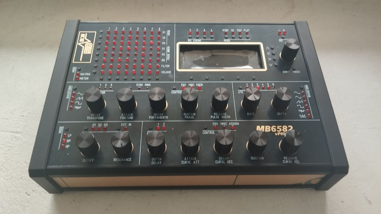
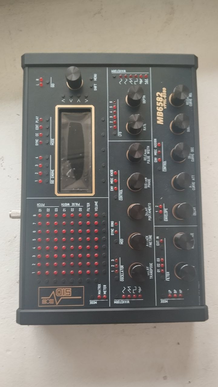
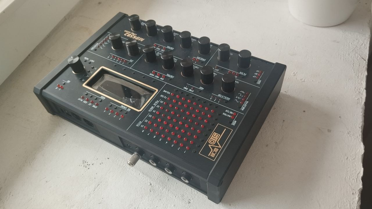
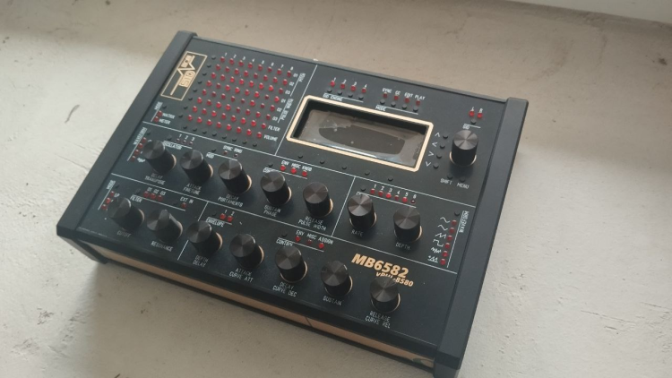
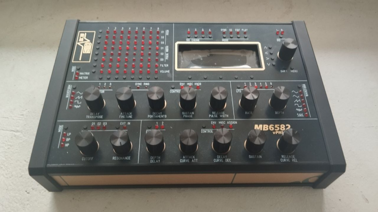
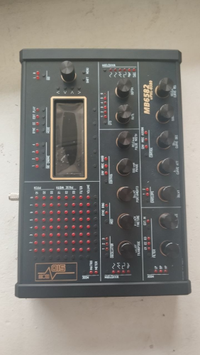
MBSID-6582 NES gray colour scheme with flat headed yellow LEDs and Caps from Elektron. Pac-Tec 10 Case1 point -
Hello how much will cost the mb6582? and also If you plan to build a sammichFM let me know1 point
-
Apologies everyone I just saw these messages. I will make a note of gathering the files tonight and uploading them to the appropriate section here (Thanks Smithy). Thanks everyone for the kind words :)1 point
-
From what I gather from the manual and changelog, this LED indicates whether you have selected a „positive values only“ waveform for the LFO (instead of applying the default workaround by showing waveform LED + Random LED). It does not indicate that the value of the LFO is currently positive.1 point
-
1 point
-
II replaces the remaining ICs and its working! Woohoo!1 point
-
Reflowed the ttasnsistors on the top side and now I am back to 12 LEDs on. I'm assuming the LEDs shouldn't be on, but otherwise that feels like an improvement as it means I get mattias switch events for 12 of 16. I'm also getting events for depresses on the right 4 encoders although they seem a bit random in the actual event details. I've also replaced IC2, IC3 and T3 based on advice from ChatGPT but that made no difference.1 point
-
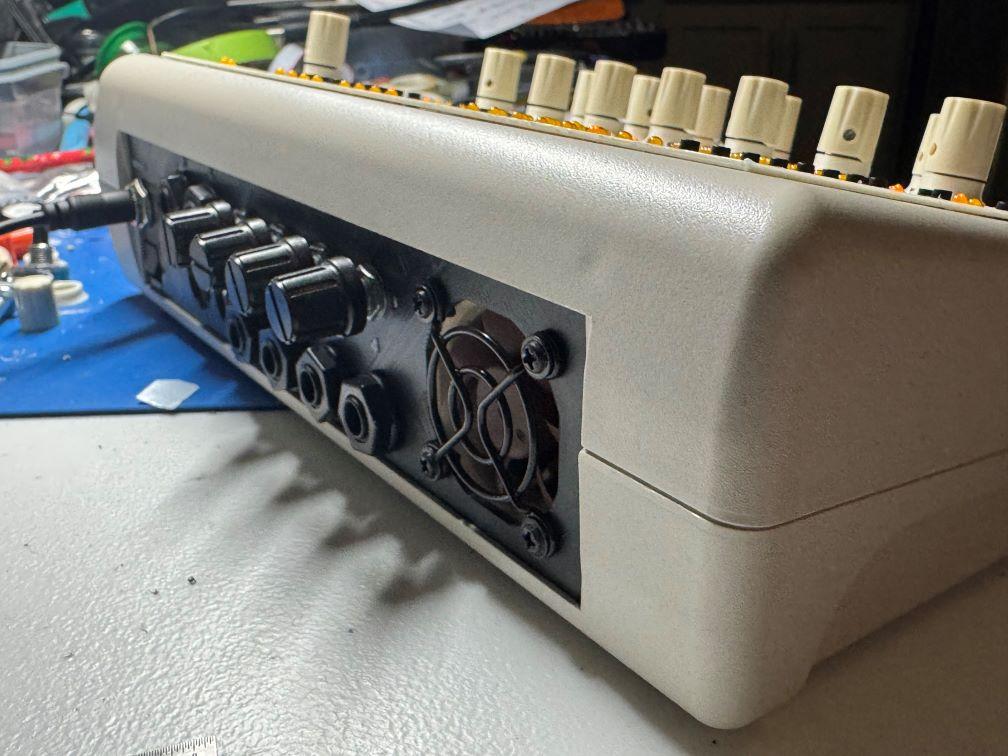
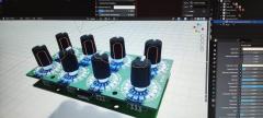
This looks amazing! With some of the older chips like vintage vca, filter or delay chips you really have to be careful regarding heat and also (or even more so) static discharge. Nowadays with most ics these issues have long been solved by modern manufacturing processes and built in safety measures. I had to lear the hard way that this is not the case with chips from the 80s... So the heatsink is probably a good idea, as would be any way to allow for some airflow. On the other hand, i have removed the fans from some of my gear with no issues at all, as commercial units have to consider every worst case scenario (crowded rack in hot environment). So if you know how you use your gear you can get away with things that could not be allowed for every scenario.1 point
-
Cool solution, looks great! The skirts for the knobs are a nice touch. One thing I wonder about is if heat would build up here, as the free air space in the case is less and the panel is also an insulator. The SIDs are on another PCB of course.1 point
-
With velocity bars there is more info displayed and the spacing is more uniform. The hyphen/minus as a spacer for natural notes helps to connect them; with spaces it is more confusing. Do you really use those low octaves so often @anonyme-x22? If it bothers you, a workaround is to transpose either on the SEQ or your synth.1 point
-
MB-6582 SOLD Selling these as I no longer use them. I assembled the MB-6582 myself. It has 6x 8580 SIDs installed, and could use some TLC: - The encoders occasionally skip counts when adjusting them. I think this is just down to a bad batch so replacing them should fix it - Some of the standoffs that attach the front panel to the CS PCB have come unstuck and need to be reglued The SEQ V4 works perfectly €500 for either unit I am based in Spain
 1 point
 -
New top as requested PM me please, or I can send the details as well.

 1 point
 -
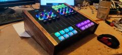
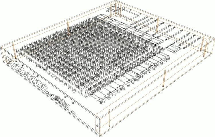
From the album: ModulBox Ng V2
1 point -
Thanks for the tpd-test app it really helped me along with this build!.1 point
-
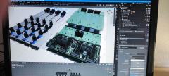
From the album: ModulBox Ng V2
1 point -
From the album: ModulBox Ng V2
1 point -
Thank's for the tip! What I'm looking for is either the fpd file which fits the Heidenreich case or maybe a ready made panel. The fpd file I found in the Wiki seems to be not specifically made for the Heidenreich case. I prever a fpd file which is proven to fit into the Heidenreich case before trying to adapt Wilbas files to the case.1 point
-
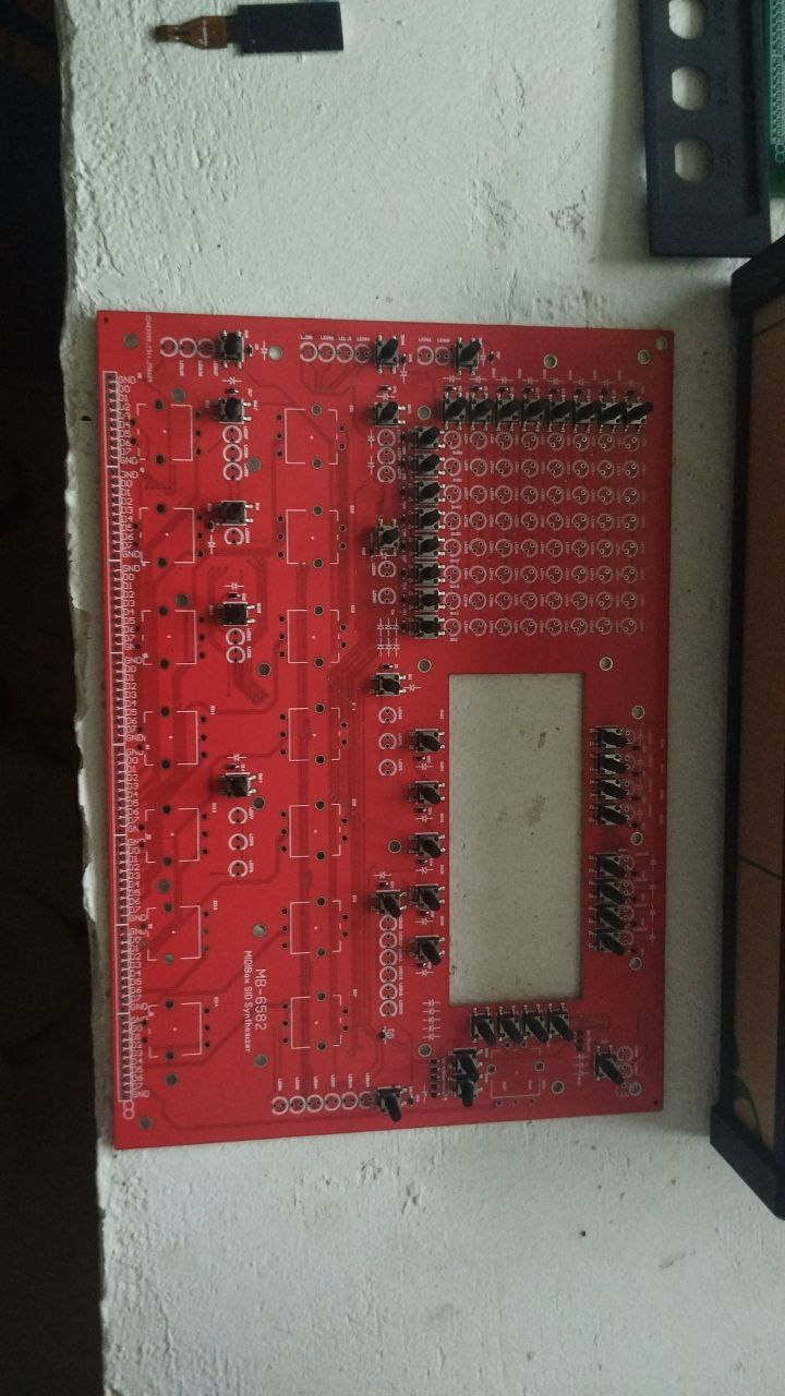
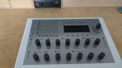
To prove that I have some PCBs here are the images of assembled sammichSIDs and sammichFM, and image of PCB of MB6582. Ideally, I would like to run a 10 pcs batch of MB6582 and for example donate 25% of revenue to Midibox project and to authors. If community and authors will approve it - I can make it. I made sammichSIDs so MB6582 would be better and more interesting. I'm just still curious if it is possible to buy originally expected enclosure. I think it is better to construct a new one using acrylic materials and probably just a PCB with a drawing for a front panel.1 point
-
If you made your own PCBs using the available schematics, then I think you may be free to sell them to others here, since they're your own derived work. However, you cannot sell the finished and fully assembled sammichSID or MB-6582 synths as commercial product without express permission. Someone else here may want to jump in and correct me if I got that wrong...1 point
-
Hi ssp, I don't remember if labels can be called from a map, but i don't think so. However, i think it is possible to change the display using a .ngr script. Bests Thomas1 point
-
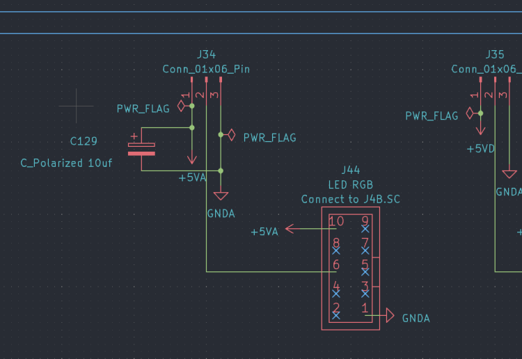
maybe its the Ripple off the PSU about your PSU - reichelt specs is saying : "Ondulation résiduelle : 80 mVcàc" i guess this is not a 50Hz ripple but HF ripple... --- i guess some small cap (100nf, 10pF) and a big Cap (depends on the load, use for example a 100uF and a 2200uF) on the output off the PSU would reduce that "ripple"... * maybe that caps are not enough and you need some more filtering (coil, resistor, lpf...) but i would start with some caps... the connections in your 2nd picture are not necessery - i guess (dont seeing the whole picture, but i think so...) --- so picture 1 is correct. by the way - its only the last LED that flickers? maybe you have to terminate the DO line on the very last LED off the Chain with a 10K resistor to 5V or Ground. else it could be a software problem, when the software loops thru the LEDs, and when it comes to the last one it jumps to the beginning off the chain... try to programm in the ng code one more LED (which in reality not exists) - so you can be sure that this is not a software bug... - but dont ask me about ng-programming --- no glue about that. - mike.1 point
-
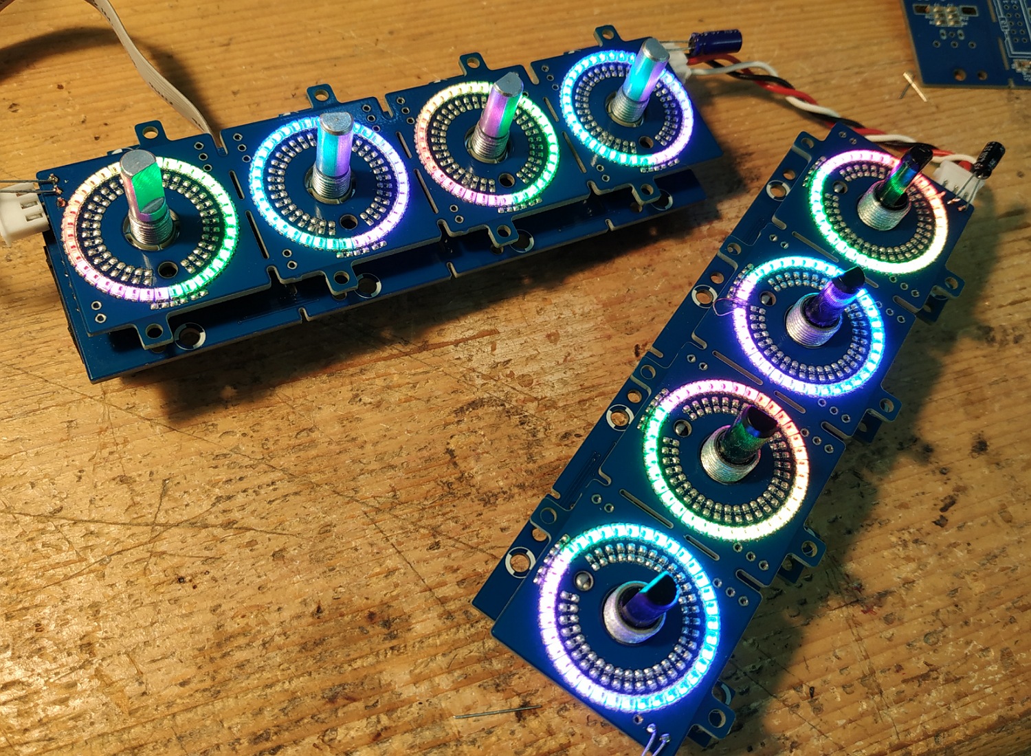
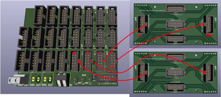
Hello, first of all thank you for your previous answers. I haven't fixed the problem with the pads yet. I'm focusing on another problem for now: with the LED rings. with 16 led ring of 16 led no problem. when I add more, the LEDs flicker. https://youtu.be/HyLkVeFtALw?si=gT09lbCxEwLRmHt8 I read here: http://midibox.org/forums/topic/21095-lre-4x1-breakable-rgb-led-ringrotary-encoder-pcb-bulk-order/?do=findComment&comment=184155 FantomXR had flickering problems, solved with a 10uf capacitor. Should I add a 10uf capacitor at the input of my LED ring cards? (as in the image below) (C129) To understand my configuration see the pdfs: LEDRING: https://drive.google.com/file/d/1XpDQBUE42IqXpXicO--B2gfIoNQDh5ga/view?usp=drive_link “power card”: https://drive.google.com/file/d/1NJ-H-QXD-tl9rU6nbYdEh2Q4jFqjWt6b/view?usp=drive_link I made a PCB that I call a “power card” that I supply with 5v 10 amps. The J2 connector of the "power card" is connected to J4b of core 32. Connector J44 of the first OLED card is connected to J3 of the “power card” Connector J45 of the first OLED card is connected to J4 of the “power card” Connector J44 of the second OLED card is connected to J5 of the “power card” Connector J45 of the second OLED card is connected to J6 of the “power card” etc.. Thank you
 1 point
 -
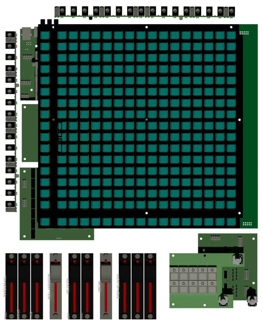
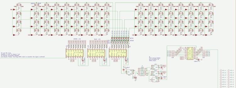
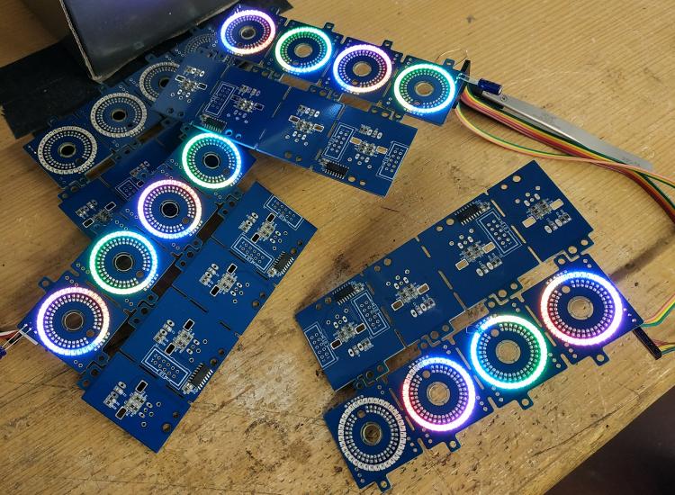
the next generation off Triggermatrix, with insights to shematic, the board-files i will not set free... the Pictures from the Boards are for debugging reasons only. where possible, i made pick and place ready boards - to reduce soldering time... at this point the big BLM16x16 board is not pick and place ready. WIKI: Triggermatrix 5 Display-Driver-SMD BLM16x16-V2 Core 4 Discovery Core 4 Disc - Midi Expansion TM5-codeblock TM5 Din Dout Gates TM5 Gate - Breakoutboards TM5 Gate - In TM5-Housing

 1 point
 -
1 point
-
Hello, I have a rebound problem with the sparkfun pads, do you have an idea how to fix this? Hardware? Software ? Thanks The rest works fine
 1 point
 -
Hi Long time I don't play with NG config, but It should be possible with enc_mode=Inc41_Dec3F , combined with fwd to 2 sender and conditional filtering, something like if_equal=0x41 send note A, and if_equal=0x3F send note B ?1 point
-
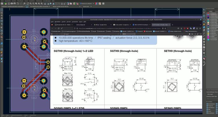
@ pusbutton: the LEDs in the shematic are REVERSED for example look into: http://ucapps.de/mbhp/mbhp_doutx4_32leds.pdf but in the board itself the Silkscreen for the Diode is painted correct - so if somebody just solder the PCB without looking into the Shematic - all is good, when someone look into the shematic he may be confused a bit. what type off Switch are using here > type it on the silkscreen - like you did on the Potentiometerboard. because: i see in the footprint its a le mec > then there are different types, with different Switch contacts - like you see here: 5GTH9 + 5ETH9 will work, while 5GTH9 with inbuilt LED will not work off course... i for me find the correct switch matching to your PCBs Footprint-Pinout - a bit hard... so label the type.... the rest off the PCB looks ok.
 1 point
 -
maybe by removing the pull-Hi resistor off the HC165 Circuit, and using a Inverter on its inputs for example: https://www.mouser.at/ProductDetail/Nexperia/74HCT1G14GW-Q100H?qs=SKY61BOKKY4Uv%2FaFLc8SsQ%3D%3D https://www.mouser.at/datasheet/2/916/74HC_HCT1G14_Q100-2937184.pdf (just a example maybe there are better parts for this porpuse, and i dont know how hard to solder this one is) that would reverse Lo and Hi, and you could use this bloddy 3 LEDs ( where i think thats not a good idea, the Encoder is expensive - and not really a standard part...) but for that quick idea i would prototype that first (order a inverter, order a Encoder, make wires without pcb) ... specially iff any pull hi or pull low resistors are needet elsewhere, i guess you need a 10K pull-low resistor (to ground) on pin 3 off your Encoder then: HC165 > Inverter > Pull-Low + Pin3 since i have not much time these times, and you have plenty off modules what module i should check next? i just had a look on your 4x2 Enc RGB SW Led ring Rgb render here... and i am not 100% sure that the inbuilt RGB LEDs that enlighten the Encodersshaft dont shine on the LED-Ring and make them hard too read (maybe need some lightshielding)... by the way hard too read, those Alps Knobs are a bit big for that small Ledring - can you still see the LEDs when looking from a angle that is not 100% from top?1 point
-
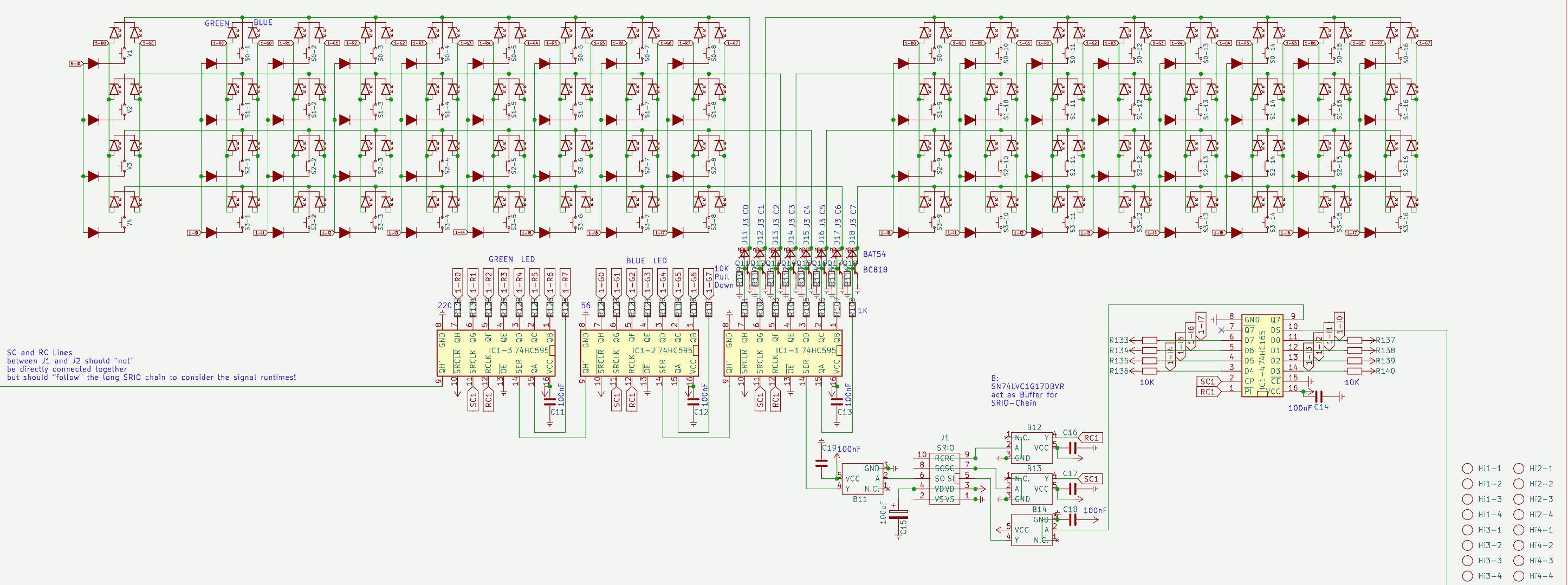
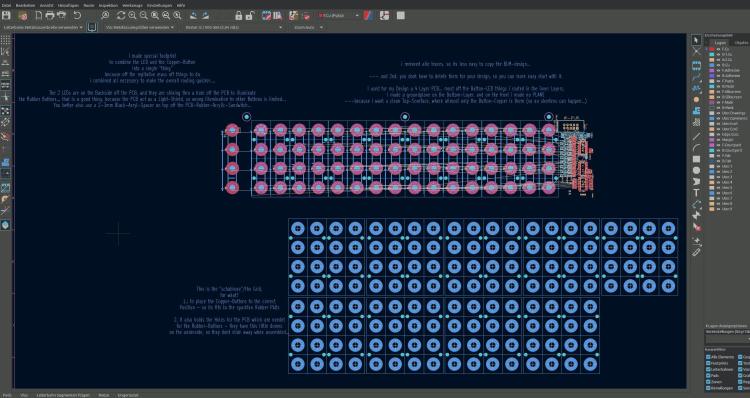
hei i stripped down the BLM-Project (so it cant be cloned with out weeks off routing U B ;) ) BLM-how-to.zip and i wrote some explaination... basicly i made a Grid with a center-cross - so a single button-LED-Fottprint can be placed correct to the Rubber-Button-Grid... you may have to set a a new "zero position off the Kicad Grid" to this crosses when you place the Button-LED-Fottprint on them... this Grid also have the Holes for the PCB which are needet to hold the rubber in Position.. maybe you find a "Flip-Chip" Variant for your RGB-LED... it would be better... you should not place it on the TOP side off the PCB... because it will illuminate the Neightbar-Button-Rubbers... The Hole in the PCB where the LEDs shine thru, act as a Light-Shield... I too have to draw a RGB-LED board (for a other Task, to illuminate a Frontpanel...), since i dont have expierence with that RGB-LEDs... this will take a while... if you found a solution i would copy it from you.... At Kicad 7... didnt know there is a stable out... good to know... will update too (else i cant check your projects)
 1 point
 -
You can leave off the USB, it's only an additional +5V power option selectable by jumper..1 point
-
at RGB-Leds > i dont know, how many you will use? which coremodule you will use? is it eurorackbased > and eurorack powerd? Which RGB-LED you will use - and what is the Voltage it needs? and so on.... i looked into your files.... some notices: @BP: dont connect the mountingholes to ground, or any other potential, best would be to make a keep out-area (sperrfläche) arround it, like i did for example here: http://wiki.midibox.org/lib/exe/fetch.php?w=600&tok=f96292&media=phatline:daw-btn-3d-b.jpg since you can plastic and/or metall standoffs to mount that pcb to the panel, you would need at least 6mm or more keepout-area.... background: you want to avoid groundloops over the frontpanel, and the risk of a electrical shock is less.... The LEDs in the diagram are connected false, the tip off the arrow should always be connected to the ground. (you should turn them 180°) which buttons do you want to use? please check the pinout off them... for me it happend that i did not connect the correct pins, so double check this.... why you made those cuts on the 4 corners? its better to make them rectangular - background: if you panelize the pcb, you have to draw a V-Grove line, the machine can only Grove in 90°, the idea, is to put 2 off this boards on one 100x100 PCB so you can save money on FAB.... way more oversight you have if you use a Groundsymbol... instead off paint Lines to a ground inside your shematic... look into "control" to see what i mean...also it makes it easyier to work with groundplanes, since this needs a NET... @Control: please open this file:Control.zip the same like above, and, you dont need that vias next to PIN 2 off the switches > Pin 2 is a via itself.... - same for Pin 1 off P2, the Problem it did not fill without your Vias: because you dont used a Ground-Net.... Pin1 - which is labeld as VDD (+) was connect to all your buttons and the pot (which is a Encoder)... normaly we connect them to ground..... VSS is ground.... so i exchanged the whole thing.... i dont know iff this is then still correct in your big picture- wiring diagram.... how ever thats the way i would make it - at least iff the Pin-Labels off the IDC Connectors are right... you should put the 4 mounting holes in the shematic, so you dont loose them when updating the PCB Also dont label your Encoder with Pot or RV >>> this is not a Potentiometer... that confused me until i realized this is a Encoder.... also the google-Drive files are a bit corrupt - the footprints where not assigned to the Shematic symbols...... when you save the project and upload it somewhere - zip it inside Kicad with "Projektdaten archivieren" - dont know the french word for it. -please overwork also your BP like/or simular like i did.... @Fader 1/2.... please open this file: Fad_2.zip shematic: also better use GND and VDD Nets.... more oversight! if you dont use a Pin off your IDC-Header (P5), then "x" them out with the blue "x" on the right side off your editor.... For what are those outer Mounting holes? they are too near to the Faders...make the pcb bigger so there is space for a Spacer/standoff, or use only the 4 inner mounting holes... which i think is enough.... again better 90° corners.... fill out your Shematics "Circuit-Field" right down - dont know the englisch or french word for "Plankopf" ... by the way you can design your own "Plankopf", so you dont see there thing like "KiCAD E.D.,A kicad 6.0.10......" keep out for mounting holes again... (see PB) dont make outher planes on VDD(+) ... mostly there can happen problems when mounting the thing to a panels, better use Ground-Planes... When looking on your FAders Footprint, and on the DAtasheet for the RA6020F then i am not sure iff the pinout is correct (the datasheet is bullshit...) but i guess you imported the Symbol and Footprint from mouser or something....then i guess its oky.... also use the design-rule check function (in a shematic and PCB-Editor) i did not looked in the other kicad-projects... but i guess its the same - a bit overwork needet..1 point
-
Yes, absolutely. Please PM me for details, ideally including your location so I can give you a shipping quote if interested.1 point
-
Looks very nice and neat .I didnt know you are so busy with things . (Thank you for your support). I was working a lot with max/msp and m4l too. Its a lot of fun , but it takes a lot of time as well :) . Enjoy and keep up this amazing work.1 point
-
look into ng documentation if there can be set a offset for the middle position so it stays on a position... because pots directly to the core is always a bit random... better use for example: http://www.ucapps.de/mbhp_ainser8.html then you have less random values also check the quality off PSU...off course a faulty pot can be the reason too1 point
-
@ cherry: the switch itself you can get already from eg https://www.reichelt.de/tastaturzubehoer-c8099.html?ACTION=2&GROUPID=8099&SEARCH=*&START=16&OFFSET=16&CCOUNTRY=445&LANGUAGE=de&r=1&SID=967792150a00d890464504461a66ae529d97182e528c945af4544 caps: amazon, alibaba,.maybe.some thing like that: https://www.amazon.com/dp/B00FYO8EDC/ref=mp_s_a_1_5?keywords=flat%2Bkeycaps&qid=1675511770&sr=8-5&th=1&psc=1 https://www.cherrymx.de/en/dev.html the low profile is maybe interesting....1 point
-
@poti; if the shaft's center is in the end on the same position - so same frontpanel holes can be used.... and: when soldering the thing: first mount the pcbs with loose potis on the frontpanel then solder it (and document this in the "how too build"... @ - : use thermal destress traces (cant remember the kicad word) when using groundplanes, so you can desolder the the poti much easier.1 point
-
1 point
-
adafruit rubber button 4x41 point
-
Very cool….well done.1 point
-
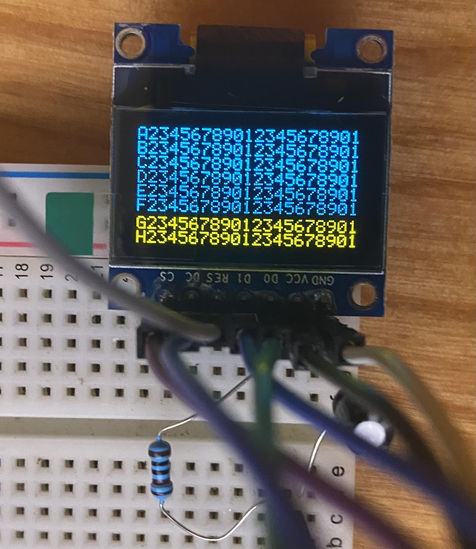
Oh, wow, I totally missed that! Thank you!!! I wasted an entire day rummaging around and didn't manage to see that :) Just in case others run across this: You want 4SPI configuration, not IIC like I have in the pic. The number of screens you have must match the configuration you set in the bootloader, otherwise you get noise, and won't be able to write to all the lines/columns Also easy to miss, but for the 1306 RES connection, you need to wire it up like this (again, connections on your 1306 PCB): GND -> 10uf cap -> 1k resistor -> VCC. Once done, RES will be tied to where the cap and resistor meet (like this) It wasn't clear to me how to actually use the bootloader for the STMF4 board, but it's essentially: Plugin your board as you normally do Open MIOS Studio Click Browse and choose the mios32_bootloader app (download here) Click Start. If it won't complete, try unpluging/pluging the board and trying again Unplug/plugin the board In the MIDI IN and MIDI OUT sections whatever app you had prior to all of this might be listed, but it doesn't actually exist (and it shouldn't). That's why you now see the error "No response...". The new app, MIOS32, took its place and you need to refresh to see it. Click Application -> Rescan MIDI Devices Click Understood in the pop-up (this will make your old app disappear, and the MIOS32 app show up) Change MIDI IN and MIDI OUT to MIOS32 Enter these one by one into the input box: (send a command to MIOS32 application). Keep in mind lcd_num_x must match the number you have chained: set lcd_type GLCD_SSD1306 set lcd_num_x 1 set lcd_num_y 1 set lcd_width 128 set lcd_height 64 store Yah. Bootloader is done. Time to restore your app in MIOS Studio: Click Browse and choose whatever app you want, like midibox_ng Click Start. Like the bootloader, if it won't complete, try unpluging/pluging the board and trying again Unplug/plugin the board Now for some test display data. Lets set some values for your SSD1306 OLED's in MIOS Studio: Click on Tools -> MIOS32 File Browser Click Create File Create some name like LCD.NGC Click Update Click on the file you just created Click Edit Text and add the following test example: RESET_HW LCD "%C" LCD "@(1:1:1)A23456789012345678901234567890" LCD "@(1:1:2)B23456789012345678901234567890" LCD "@(1:1:3)C23456789012345678901234567890" LCD "@(1:1:4)D23456789012345678901234567890" LCD "@(1:1:5)E23456789012345678901234567890" LCD "@(1:1:6)F23456789012345678901234567890" LCD "@(1:1:7)G23456789012345678901234567890" LCD "@(1:1:8)H23456789012345678901234567890" Click Save You should now have 8 rows and 21 columns of text. If you need to flip it 180 degrees, you can redo the steps above and add set lcd_type GLCD_SSD1306_ROTATED before you store.
 1 point
 -
Hi Therezin, I mounted the monitor upside-down because of the viewing angle. This specific monitor has been designed to be looked at from above. It's actually pretty good from around 10° to 90°, but from 95° to 180°, the visibility is very bad. Therefore i had to reverse it so when i seat behind my desk, i'm in the good range. Let me know if this explanation is not clear enough, it's pretty hard to describe in a foreign language. Thomas1 point
-
Hi guys, I don't know the best for your project but I can explain what I did for the OLRE16. First is the MASK, it's black PMMA. Both sides are milled. I let some space between the leds on the pcb to keep some matters between the leds housing. Led size is 1.5x2mm On the other side(front side) there's some stripes which will fit inside the translucent PMMA, they will block the light between the leds, between the rings and between the rings and the oleds. . Note: the olre16 top pcb(ring) has no component on the top except the leds and the oleds. In blue are the back leds housing. In Red there are the holes. In Yellow, some stripes to block the light on the front, those stripes will fit inside the back of the translucent PMMA. The second part is the 'WINDOW', in translucent white PMMA, it's a LED special one, the same I used for the beat led window of the Seqv4+. The back part will fit inside the MASK, in other word the base of the WINDOW will receive the MASK's stripes, of course the WINDOW's pipes are in front of the MASK's holes. Then the Aluminum front panel comes to finish blocking the light and the pipes of the WINDOW will fit inside the panel, flush the surface. When they are coupled When coupled , assembled the thickness without the pipes height(front panel thickness) doesn't exceed 2.5mm Voilà! I don't know if it will help you and It's surely an "over-engineered" thing but this is the only solution I found, and it works. Best regards Bruno1 point
-
Hey people, thanks to @TK.! It's working great. Anyway I had still some flickering on the LEDs. As I stated above I left away the caps ... and this was the reason. I know have added a 10uF on the input and on the output-connector of the LED-rings and the flickering is completely eliminated! Great!! So, one core can handle a total of 10 LED (10*36=360) rings....
 1 point
 -
Good. Maybe someone need good midi samples for beatmaking www.lucidsamples.com/edm-samples-packs/278-edm-magical-midis-vol-3.html and https://www.loopmasters.com/search?q=midi1 point
-
Hi everyone ! I experienced the same problem, and The Ancient One's solution works perfectly for me. I changed the 220R resistors to 68R for R21 and R22. Now the 9090 detects the signal without any issue. Thank you a lot Michael ! Théo1 point